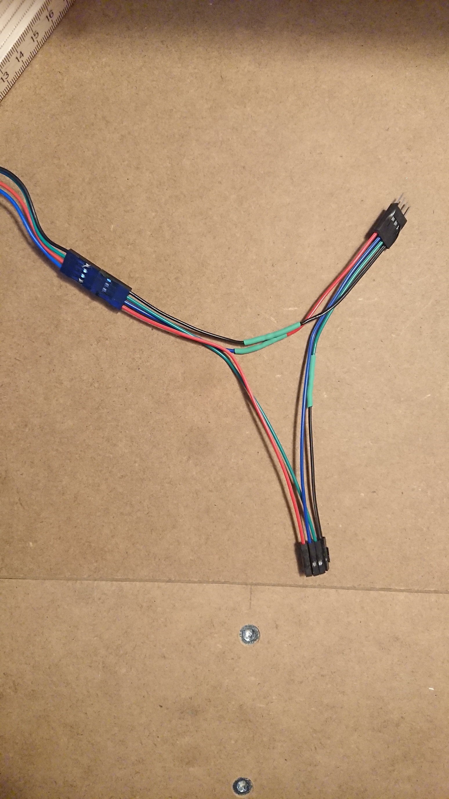
Until my RAMPS board arrives I started making a couple of serial Y connectors using pretty standard Dupont jumpers. The retailer states that AWG is 22-26. I don’t know why it’s a variable number but I guess it’s because, you know, China. Is that a problem? The circuit is quite short and the dimension seem to match the stepper cables. What should I look out for? Warm cables?
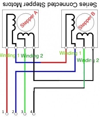
Next, I have some mild confusion about the coil coloring. The red and blue are switched when looking at the wiring diagram. But I’m reading that colors don’t say anything about their true nature anyway. If my understanding is correct, the polarity doesn’t matter, only the pairing? So even if the red and blue were switched but were connected to the same coil, I’ll be Allright? !
Carefully follow the wire on the drawn picture where the black wire starts at Winding2 on Stepper A
It goes from rightmost (pos4) to rightmost(pos4) on both Windings.
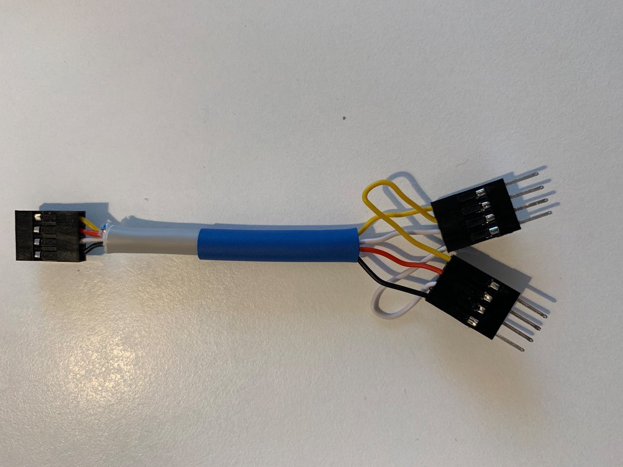
Look at the picture taken of a set of wires done and follow the same wire(white)
It goes from pos 4 to pos3 on the next connector.
On the hand drawn diagram you can follow the line from #4 botttom connector (black, changes to greeen) and it goes into pos3 on stepper 2
It is messed up on the pos3 & pos4 on the 2nd stepper wires on the photo.
So which one is correct?
That is what made me connect the extra stepper-drivers I had as spare and opted to go single cabling all way. As is now only firmware for dual endstops activates the dual steppers so that is what I went for.
If you check this chart (the Chassis wiring column) 26g is rated for 2.2 amps while 22g is good for 9 amps. So I think you’re OK even if it’s at the lower range, and it looks thicker than 26g to me.
Maybe that’s the range of wire that will fit in the connectors? Is there a size printed on the wire?
the polarity doesn’t matter, only the pairing?
The instructions call for the polarity of one pair to be reversed on one motor, because the motors face each other and need to run in opposite directions. However, just reversing the plug will also reverse the motor so I think you’re right that it doesn’t really matter - at least when you’re using easily reversed connectors.
If the motors had solder terminals and you were having to hard-wire everything… you would have to be mindful to cross over one winding of the motors, per the schematic diagram… if you wanted them to turn in opposite directions.
But where you have the “extra” Dupont connectors in the cable to each motor… it doesn’t matter, as Robin said. You simply flip the connector to one motor to reverse its direction, if needed.
Your photo is exactly the way I do my homebrew series-wiring adapters and it works a treat.
Thanks Robin! Since I have separated the Dupont connectors, I guess I just have to fiddle around with it until it works and that I don’t need to worry about breaking anything. We’ll see on Monday when my board arrives. It’s very exciting, thus far!