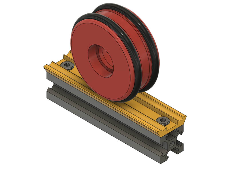
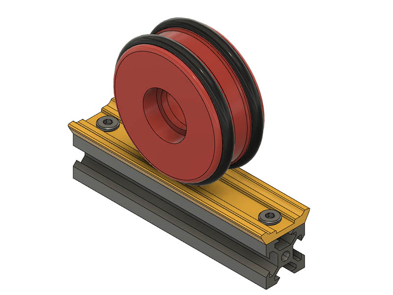
I was thinking the other day that it is too bad this machine would not be accurate enough to make a rolling 3d printer as the wheels will get off too much over time. This morning I had the bright idea to make a track for the O-Rings to roll in. It still might not be good enough for a 3d printer, but should help the wheels stay on track. I created this 100mm test length to see how it feels. I barely had clearance for 2020 for the screws, but it might work.
This is probably a better idea if the tires print well in TPU. These tire profiles match the V-slot wheels. Since I am running along V-Slot, making the whole wheel plastic might be even better & get rid of the TPU tire all together.
Making it all plastic might even be a better idea since the plastic is rolling on the V-slot
and wrap a rubber band around the V 's for better traction if needed. This also gets rid of the problem of joints at the sections of track & less to print in the long run.
If I were to do that I would not use the V profile, that magnifies the errors way to much for my liking. I would use the surface and straight fin that goes all the way in the slot to keep it on track, or the inside or outside surface. I have not done any real testing but that is what always sits poorly with me about that v slot stuff. Maybe even lock one side and let the other side just float. I could be completely wrong though.
Some guys (Jeff IIRC?) are putting curbs/guides on their LR2… I see this pretty much the same way. Maybe just a guide of some sort, laid out on the floor for one side. A “track plotter”?
I have some hack tracks on my LR1. Just a guide on the inside of each wheel. The wheels are rubber though, so if there is any error, it will squish out.
For a v-slot rolling like that, what radius do you use to determine the linear travel per revolution? It seems to me it could be inconsistent where it sometimes rides on the inside edge and sometimes on the outside edge. This wouldn’t be a problem if like LR2 the wheels were not driven but for it to be driven and repeatable it’s a consideration.
Also if you were going to the trouble of printing a track, you might as well print a herringbone rack/pinion that should go a long way to improve repeatability in both directions. Maybe you could have an O-ring in addition, with the diameter of the O-ring larger than the outside of the spur gear, and you could have the option of riding repeatably on a rack or less repeatably on a smooth floor.
That was apparently just a passing idea. It is getting away from the original intent of this design & doesn’t look worth pursuing anymore than I already have. I am making some thicker TPU tires that might work just as well as the O-Rings. I have 6 more to print before I can test them. I did have to add an extra washer between the frame & wheels as the tread on this design hangs over a little & seems too close to the frame. I will see if it is better to change that before printing the rest of them. I kind of like them hanging over the edge. It is a question of whether I have to go to longer screws on the idler pulleys. They are currently 30mm & don’t really want to go 35mm.
Here is a test run using the thicker TPU tires. They are a tight fit & looked promising. I pinched my finger getting one of them on. Test print was not as accurate as the O-Rings. I also did another test print with adding rubber bands around the wheels & that was better, but I really needed wider rubber bands & don’t have any on hand, so will test that another time. I was thinking adding treads to tire design might help.
Here is the video with the TPU tires.
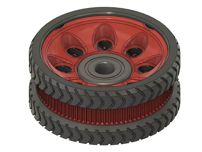
Here are a couple of my ideas on adding tread to these tires.
I made a case for my Raspberry Pi 3B+ in this design to protect a little more. I used https://www.thingiverse.com/thing:4054637 which is for the RPi4 as guide to make one for the 3B+.
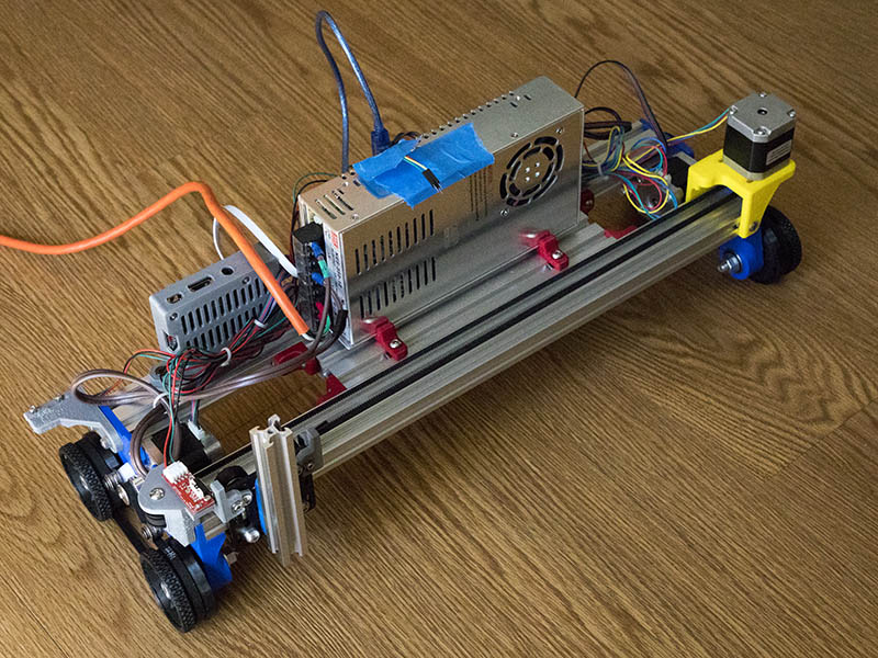
I changed the Carriage Idler mount & the carriage belt clamps to the new versions, but belt was not long enough to add the new motor end mount. I went from 375mm maximum width to 392mm maximum width (2040x500mm extrusions) with this change & when I change to the motor end mount should get another 12-17mm width. With these changes, there will be 9 less T-Nuts used. The only T-Nuts that will be used are for the electronics brackets & Z-axis Pen Mount (10-12 T-Nuts). The T-nuts in the design did make it easier to take the Wheel endplates off & on easier while adjusting the design. I have enough belt to make 1meter version, so will add the motor mount on that design. I should have over 35" of travel with 1 meter lengths. Here are a couple of photos.
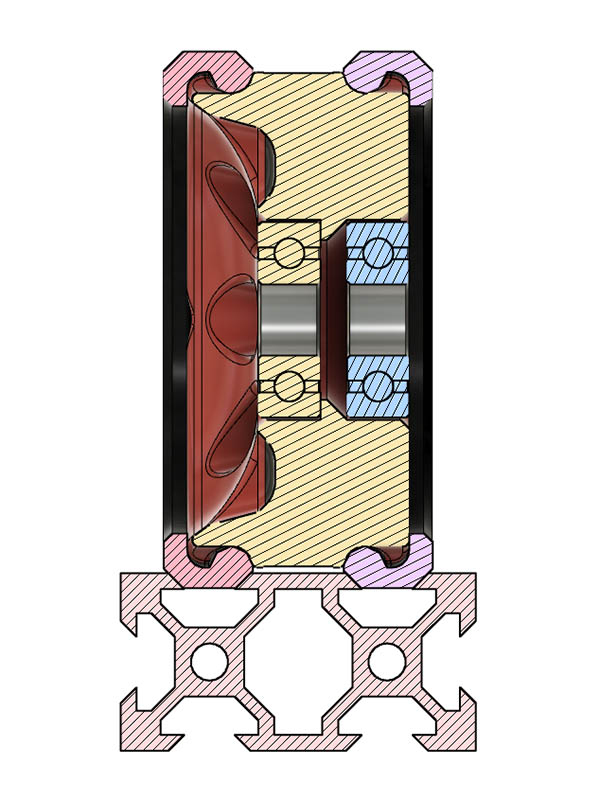
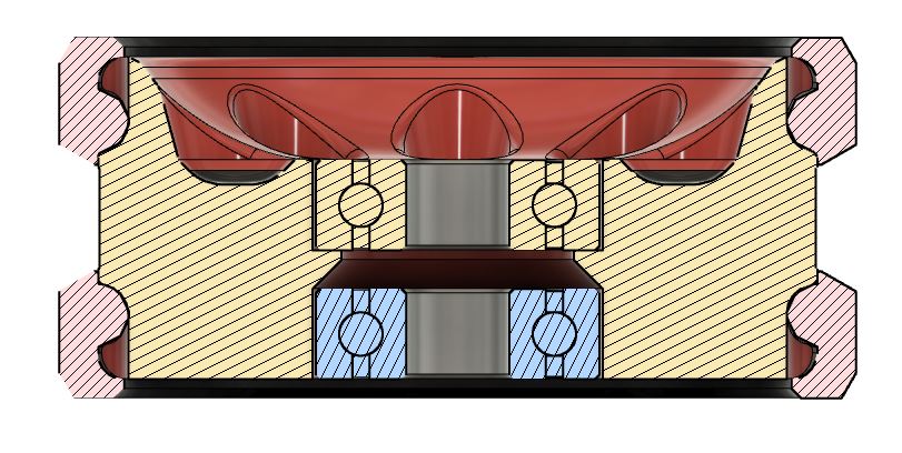
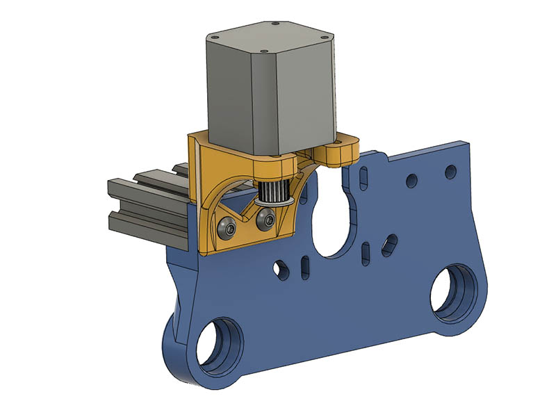
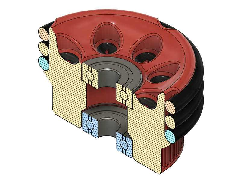
Since I will have a few extra O-Rings after getting a pack of 50 from Grainger, I decided to look at using 4 O-Rings on each wheel with the belt still between the O-Rings. It moved the belt a little further from the end plate & the 20T drive pulley was extended out further that I liked. I pondered it some more & decided to try moving the belt path to the inside of the wheel. Since the teeth are now on the outer edge, I am not tied to making them 88T. After some trial & error on different teeth count, 76T looked like it would work well with the closed loop belt I have. Having the O-Rings on the outside of the belt path also allows me to change the O-rings without taking the wheels off the plate. I spread the bearings apart about a 1/4", so I will need 2 1/4" bolts instead of 2". 2 1/4" bolts are not always available locally, but could use 2 1/2" bolts with some extra washers.
Has anyone ever tried 8mm Shoulder Bolts with the 608-2RS bearings. The ones I need are $1.72 versus $0.32 for the M8 Hex bolt, but I only need 4 of them. It doesn’t feel like I am getting any play in the wheels with the 5/16" bolts, but just wondering if anyone has experience with these. https://www.boltdepot.com/Product-Details.aspx?product=14243
Not shoulder bolts as such, but the MPCNC is a mix of longer bolts (with a smooth section) and short machine screws (threaded all the way) and it doesn’t seem to make a lot of difference whether the bearing rests on a smooth or threaded bolt. It might if the load forcing the bearing onto the threads was enough to deform the threads, but it’s all pretty lightly loaded.
Thanks for the info. I had already leaned towards buying the partial threaded bolts just so the bearings wouldn’t have as many threads to rest against. I might buy one shoulder bolt just for reference when I place an order. The fact that they are M6 threads on the end of M8 shoulder bolts, I would probably have to make a plastic washer on that end to rest on the bearing as the M6 washers might not have a big enough OD & fender washers are probably too big an OD.
I’ve been passively following Dave’s rolling plotter project, so now it seemed a good time to fire up the Prusa and at least print the wheel plates to play with. I’ve already ordered the 444mm belts Dave specified but they’re stuck on the slow boat and I don’t yet have them to play with. I also don’t have, or print with, anything but PLA so can’t print belts as Dave did. I did, however, once purchase some 60mm skate wheels from Ryan for my FoamRipper project… and a set of extras for a possible LR2 build. So I’ve started piddling with what I have on hand…
I downloaded one of Dave’s wheels from Thiniverse and “borrowed” the GT2 pulley section using TinkerCad… in hopes the 444mm belts (when they get here) might actually have a chance of fitting. I then combined the pulley part with a passive hub for one side of the skate wheel and another simple hub for the other side… these sit where the wheel bearings normally go but now just “lock” the wheel and pulley when tensioned by the axle bolt/nut.
I know these wheels won’t have a lot of traction but they are pretty “grippy” (maybe equivalent to an O-ring?) and may be enough for light loads; i.e. pen/marker, stylus, needle cutter, and possibly a laser. Right now, however, I’m really more interested to see how straight/true these wheels run… they run quite nicely on the FoamRipper. I’m sure a guide/curb of some sort will probably be needed for actual use… sort of like a track saw. At the very least, I should now have something to roll around on the floor and start playing with. It’s not much… but it’s a start.
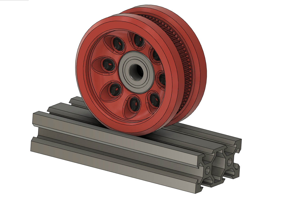
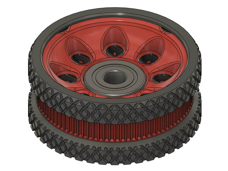
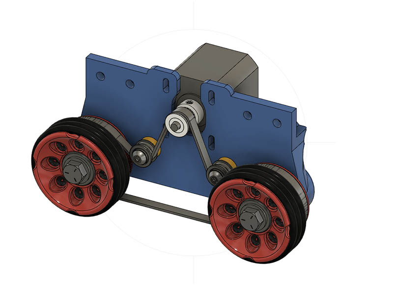
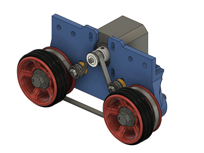
Glad to see you are making some progress with it. If those wheels have some grip to the, they should work as well as the O-Rings. That looks like a good way to use those wheels & nice to see another option. Think I have the wheels & plate the way I want them for the version 3 of this design. I put in an order from boltdepot.com today & added some metric screws missing from my inventory to pad out the order. I decided to go ahead & get the M8 hex bolts for the wheels so it will be all metric now except for the O-Rings. The M8 locknuts from McMaster catalog inserts in fusion 360 are a little thicker than I thought, so I ordered M8x60mm bolts. I will wait until they arrive before looking at fine tuning the thickness of the wheel. My calcs for 1st assembly of the wheels & plate of this version were a little off, so I made a drilling template to redrill those idler slot holes a little more rather than reprinting that 4 hour plate. My new tooth count on these wheels is 78T. The print slope coming off the 76T was still a little ragged since it was less than 45degrees. I also put a lip on the inside of the teeth to make sure the belt didn’t come off. Another advantage of this new design is the belt doesn’t ride on the floor at all. Here is what the design looks like now.
I have about 6.5mm of motor shaft extended beyond the 20T driver pulley, so I am thinking a cool looking extruder visualizer might be cool to add to it. Here is one Jeff will like. https://www.thingiverse.com/thing:3135172