Hahaha. That would be work the entertainment alone. If it ever roller plots, bonus!
A hamster would work. Or else, Who is the greek myth that keeps pushing the rock up a hill?
Hahaha. That would be work the entertainment alone. If it ever roller plots, bonus!
A hamster would work. Or else, Who is the greek myth that keeps pushing the rock up a hill?
how about this artwork. https://www.freeart.com/artwork/art-print/gearwheel-man-character-running_fa28519199.html
Sisyphus
Oh man, I should have known that. Sisyphus has totally reassociated with the sand tables in my head. Thank you.
I mainly know of him because of the late, great alto saxophonist Phil Woods.

I have klipper firmware running perfectly on my rolling plotter now. It solved my servo problem of staying in sequence with G1 gcode drawing sequence. I created a G10 & G11 macro for the pen down & pen up movement. Klipper even allows Multi-stepper axes to use separate stepper driver for each motor which I was also doing with the Marlin firmware. I have one bad bearing to still resolve which is noticeable in the video. F695zz flange bearings have worked the best for me & I just realize I have them on my folgertech Delta I could borrow for a while. That is why the one side is not rolling properly in the video. I still have the TPU 3d printed belts on there, but should be able to test the real belts later in the week. I am letting the belts sit in the shed for a few days before trying them.
Very cool.
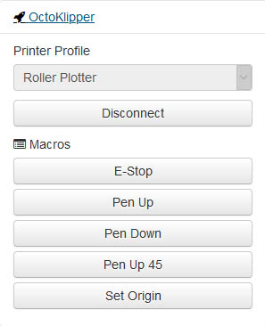
I got the bright idea yesterday to shorten the 3d printed TPU belt by 8mm since it stretches a little & the 2nd test print using it worked the best so far. I found another F695zz flange bearing, so all the idlers work great now. I can tighten the screws all the way down & they still turn nicely. I have 8 of those bearings used now, 2 for each idler. I had a loose grub screw on one the wheel motors which was probably causing part of my problem before. It is still not rolling perfect, but I didn’t see any missed steps this time. I am really liking using the klipper firmware with this machine. There is also a octoprint plugin called octoKlipper that adds a little more flexibility to it like adding button macros for specific code. Here are the buttons I made so far.
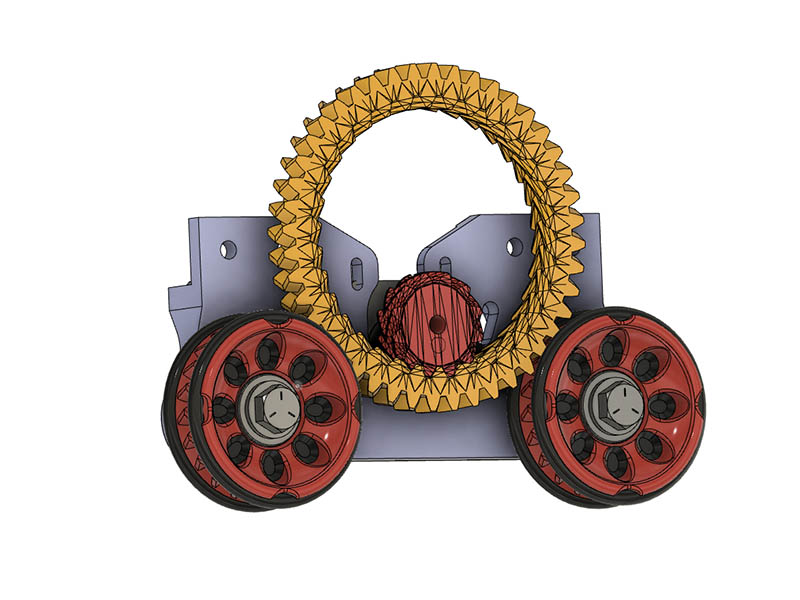
Think I figured out a way to get the correct inner ring gear draw correctly with this Ferris Wheel or I like the term Jeff used for it, a Hamster wheel. I created the drive gear & inner ring with openscad using https://www.thingiverse.com/thing:53451 I then merged that with a 44T double Helical gear for the outer ring which is 105mm outer diameter in fusion 360. I will probably have to use 2 or 3 bearings rolling along the flat part of the ring to keep it from wobbling, but will just print it for now to see how it meshes. Might have to create some sort of tunnel for it also so it doesn’t wobble the other way, but 1st things 1st. Looks like that big ring is going to be a 2 hour print. I was thinking I could put a idler bearing gear on those end V-slot connections, but the distance is too short to get a gear in there with the current specs I am using.
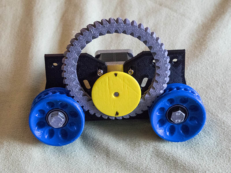
I printed the hamster drive parts & put it together for a test fit. I added a flange around the drive gear to give the wheel a little stability. Looks like it will need some bearing support to not wobble, but looks pretty cool. The gears work the way they are supposed to, but probably need to make the ring gear 1 or 2 teeth larger. It would also be difficult to adjust the bottom 2 motor mount screws after that wheel is in place. I may play with some bearing ideas, but will go back to my belt design that works for now.
There must be some perfect application for the hamster wheel drive… I like how it sort of gives you a huge handle to push it, although it is toothy.
That looks great, I’ve love it see it in action!
Could you leave (or drill) four holes in the yellow wheel and a couple of holes in the ring gear to allow access to the motor screws?
I think if you could just make two idler gears go to the upper inside of the big ring, it’d stay in place.
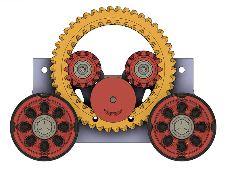
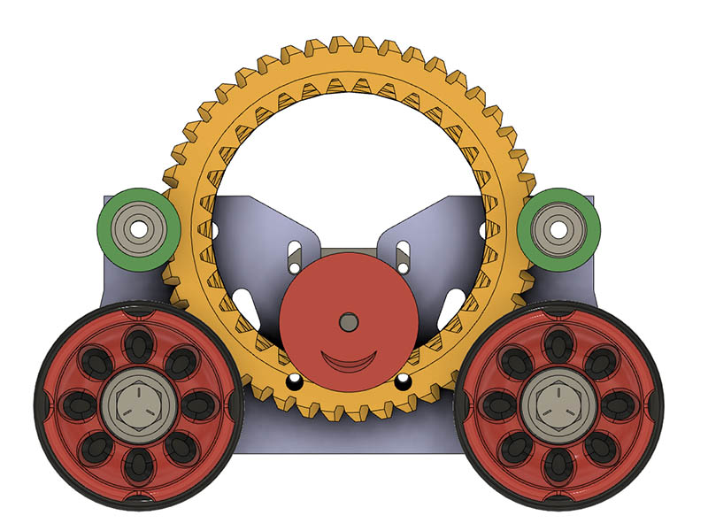
I had thought about adding the holes to the big ring gear for the motor tension, but at the time I was considering using rolling bearings along that surface & thought the holes would interfere with the smooth rolling. I had to decrease the diameter of the drive gear flange for the holes to work. I wasn’t sure I would like the look of the 2 idler bearings that Barry suggested, but modeled it to see what it looked like. I kind of like it. Looks like a big smiley face, so I put a smiley mouth on the drive gear. I was also going to put a frown 180 degrees to the smile, but that didn’t look good. Looks like I have enough room to add those idler bolt holes to the frame, but sadly I will have to reprint that. I will ponder it for a little while before printing it in case a better idea shows up.
I meed this just sitting on my desk. With little arms on the wheels. It can spin whenever I get a new forum reply.
To avoid needing to access the lower motor screws, I’d snug them until there was no slippage back to front, maybe adding washers if needed, and use the upper 2 to lock them in position up and down once things were aligned where they need to stay.
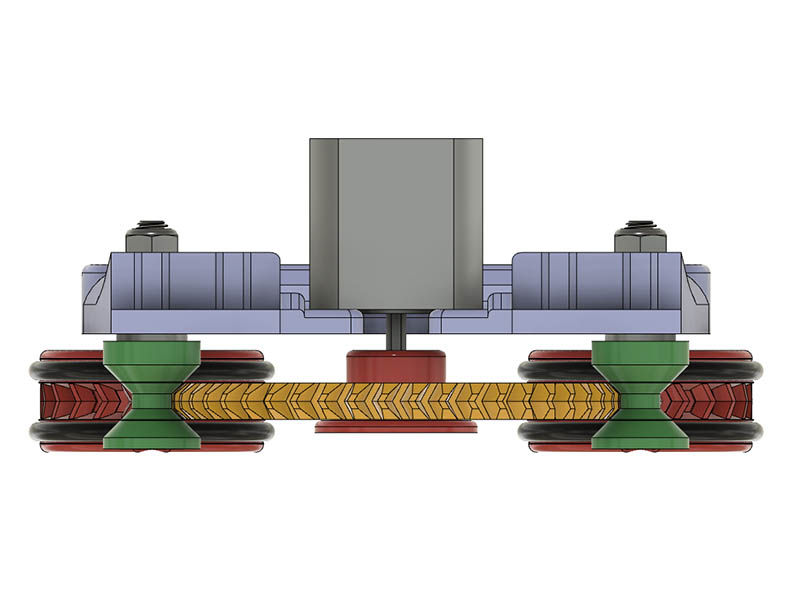
I guess you are talking about something like fender washers? I might could put them on the top 2 gears, but not sure how it could work on the motor connection. I added a back flange to the top 2 gears which should keep it from wobbling towards the plate.
Edited my previous post to (hopefully) clarify.
Along a different line, what prevents making the motor gear smaller? On the original with idler spur gears, there is a constraint where all teeth must be the same size, but in the current configuration the motor teeth and wheel teeth need not be the same size, either in pitch or in the axial dimension.
A herringbone gear is more forgiving than a regular spur gear with fewer total teeth since the teeth cover a continuous range of phases. And additionally if tooth strength is a problem the gear can be made larger axially, so smaller teeth are possible as long as they can be printed.
This might give you a better gear ratio. With a smaller motor gear you might have to be more creative in how you attach to the motor shaft but there are several possible ways to approach that.
caution… thread drift…
Put one more wheel on the other side so it can drive. Mount a shelf on the wall above your monitors. Left side is “All Posts Read” Right side is “You’re way behind”… As the number of unread posts increases it slowly creeps across the shelf until it gets to the right side.