That idea would have been difficult to explain without a drawing. I am going to make a parametric fusion 360 & maybe an openscad file for the pulley I made in case I want to use different bearings or change other variables easily. It shouldn’t be much to it. I might also add the option for 16T or 20T in the mix
1 Like
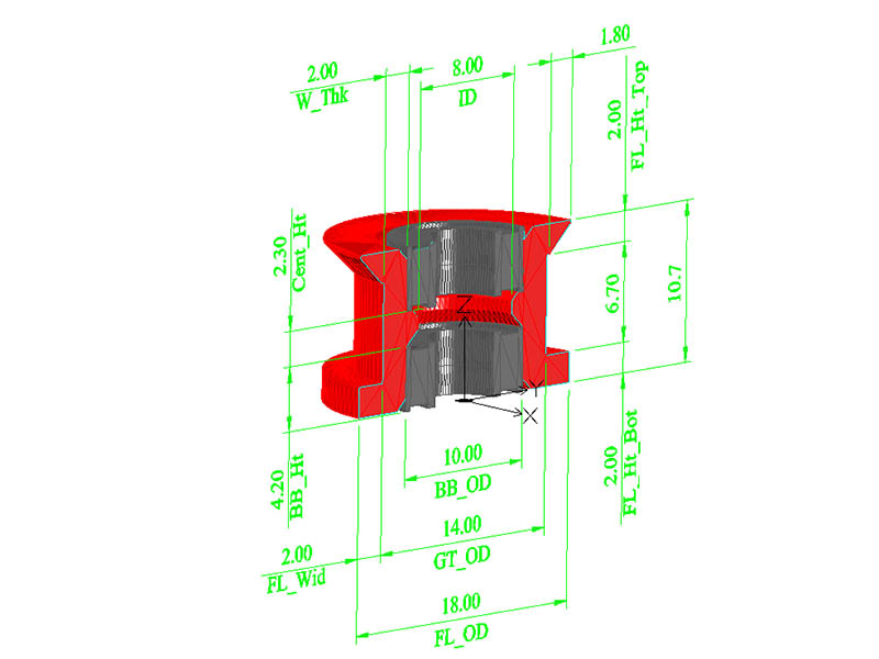
I made a parametric openscad file creating these idler pulleys & attached the zip file here since thingiverse is having some problems. I created 4 sample STL files & included them.
Idler_Pulley_105zz_Bearings_L_Rev1.stl Loose fitting (.35mm tolerance or .7mm bigger diameter than bearing)
Idler_Pulley_105zz_Bearings_T_Rev1.stl Tight Fitting (.2mm tolerance or .4mm bigger diameter than bearing)
Idler_Pulley_625-2RS_Bearings_L_Rev1.stl
Idler_Pulley_625-2RS_Bearings_T_Rev1.stl
Idler_Pulley_Bearing_Rev1.scad
Idler_Pulley_Bearing_Rev1.jpg
I use the .35mm tolerance so I can get the bearings out if I need to. I am also using .5mm nozzle which seems to need a little more tolerance on my printer. Here is a drawing showing what the variables are in the file.
1 Like
I was about to get on thingiverse this morning, so I uploaded the idler pulley bearing design there & also made a version in fusion 360. https://www.thingiverse.com/thing:4244501
1 Like
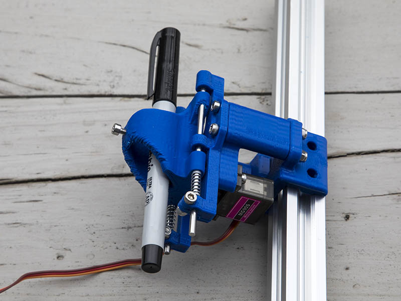
Here is the pen mount I came up with. I remixed https://www.thingiverse.com/thing:2349232 to fit my design. The smooth M3 rods came from an old DVD player which was mentioned in the original idea of this. I used a spring from a pen from dollar store & cut the spring in half. I should be doing another rolling test tomorrow.
2 Likes
Here is a test of the servo for the Z-axis using Marlin firmware. https://youtu.be/0sjkk_cb8Ls
The servo is not implemented for this unless I use a special branch that has “SERVOSTEPPER” option for Z_DRIVER_TYPE. Here is short video showing my problem. https://github.com/MarlinFirmware/Marlin/pull/9935
I tried using this branch, but it doesn’t work for me. It works about the same as what it did before, but maybe a little slower servo movement. I don’t know what extra settings to make at this point. Anyone know what additional changes I would need to get this to work? I might be better off just using a small 28BYJ-48 stepper motor which should be easy to implement in current pen holder design. Here is the Marlin branch I used: https://github.com/TheSFReader/Marlin/tree/servo_stepper_feature The only other change I made to use the servo was:
#define Z_DRIVER_TYPE SERVOSTEPPER
#define NUM_SERVOS 1
Here is the test GCODE I made:
;Test drawing Center Line with servo motor along Y-axis
G90
M280 P0 S80 ;Pen Up
G00 X0.0 Y0.0 Z0.0
M280 P0 S0 ;Pen Down
G00 Y65.5000 F1200
M280 P0 S80 ;Pen Up
G01 Y77.5
M280 P0 S0 ;Pen Down
G01 Y97.5
M280 P0 S80 ;Pen Up
G00 Y0.0000
1 Like
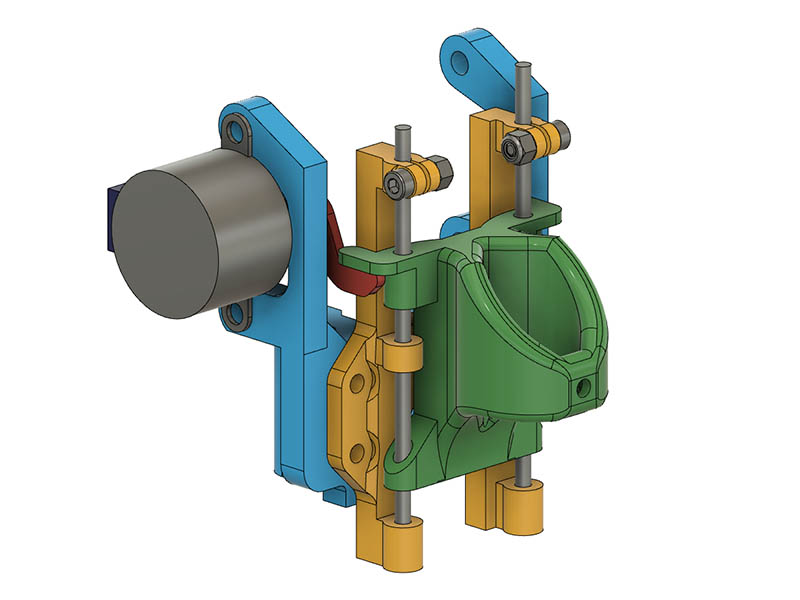
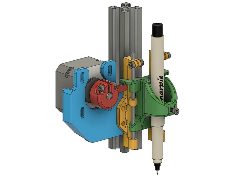
I didn’t make any progress with getting the servo motor to work correctly, so I decided to let go of that aggravation & work on a mount for a stepper motor. I first made a mount to use the small 28BYJ-48 5v motor, but that looks kind of kludgy to connect it all up. I have a nema17 pancake motor that is only 4.8oz so that is what I intend to use since it is a simple one cable connection to the controller board. Here is a screen shot of both of those mounts.
1 Like
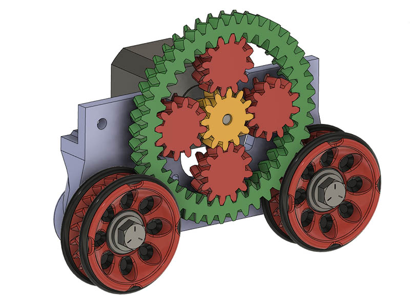
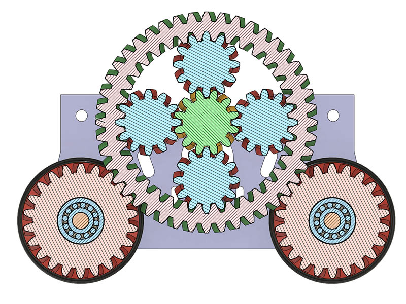
Looks like my timing belts will be here any day now, but in the meanwhile I had a wild idea about another version of gear drive. Since I need a small drive gear for more torque & the intermediate gears would not mesh well, what about a planetary gear drive? After about an hour or so of drawing in fusion this is what I came up with. I could use my 2 or 3 of the small bearings rolling along the edge of the outer planetary ring as I mentioned in a previous post if it gets wobbly. I also have to mount the motor a little higher up. I think it looks pretty cool, but whether it works or not might be a different story. Not sure I can get them to print in place meshed with the fusion 360. That parametric openscad planetary gear file I have seen might be better for that. I have 12T sun & planets. Inner ring is 36T & outer ring is 44T & the wheels are 22T. Does that still give me a 1.83:1 gear ratio from 12T drive to 22T Wheels like the regular gears give or are planetary ratios figured differently?
3 Likes
That looks like a bunch of fun.
1 Like
Cool, but sadly I don’t think it will work as drawn. Either the ring gear needs to be fixed and the planets (generally on a planet carrier) are the output, or the planets are fixed and the ring gear is the output, although in that configuration there’s the same reduction as the sun gear turning on the ring directly.
Having said that, there are similar designs for compound planetary gear sets that can give very high ratios, which could be promising.
3 Likes
Oh, yeah…
2 Likes
That is why I post the idea. Thanks for the expert advice. This video seems to be what you are talking about. https://www.youtube.com/watch?v=5a1w9daIybc
1 Like
Yes! I am a fan of GDFW, and I even messed around with compound planetary gears myself a while back, inspired by his design.
One of the cool parts about his design is that no planet carriers are needed, which simplifies things significantly.
1 Like
A simple solution would be to remove the sun gear and just drive the bottom planetary gear, which could then be smaller if you wanted a lower gear.
Do herringbone gears hold each other in alignment?
I love the look of the design, and the idea of printing it all in place. This kind of design would have been almost unthinkable 20 year ago when I started building stuff.
Also, you have a great opportunity for writing a cyclical message on the ring gear:

or this

3 Likes
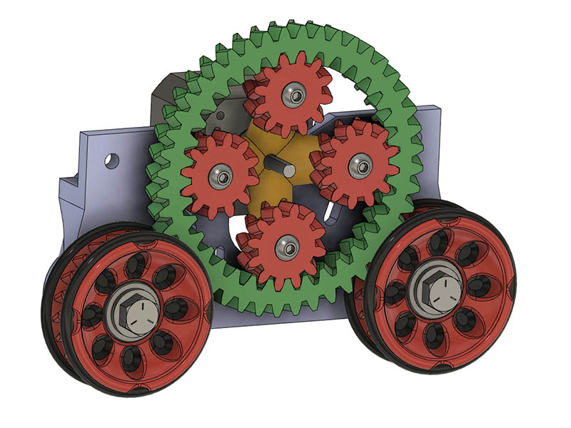
I am not sure how you mean to drive just the bottom gear. This is the closest I was thinking of what you meant, but looks like the same problem that Jamie mentioned. I drew it as essentially 4 spokes, but could also be a tapered cylinder. The 4 spokes look cooler.
I also may have found a solution to using the servo for Z-axis. Yesterday I started looking into using klipper firmware instead of Marlin & posted a question to the klipper community on facebook. Someone mentioned using a retract macro for it. With a google search I found this page. https://github.com/KevinOConnor/klipper/issues/824 That looks like it should work. For the retract, I will just substitute
M280 P0 S80 ;Pen Up for G10
& M280 P0 S0 ;Pen Down and G11
I wonder if I could do something similar in Marlin & overwrite the G10 & G11 commands since I don’t need filament commands with this configuration? I have configurated klipper before, so the klipper firmware shouldn’t be too difficult. Looking thru the marlin code, there appears to be macros M810-M819 that can be used.
1 Like
Sorry, I meant drive one of the planetary gears - basically just a pinion turning the inside of the ring gear and not a proper planetary set up at all.
In reply to your newest drawing, yes it would have the same problem, unless you added a sun gear that was somehow fixed.
1 Like
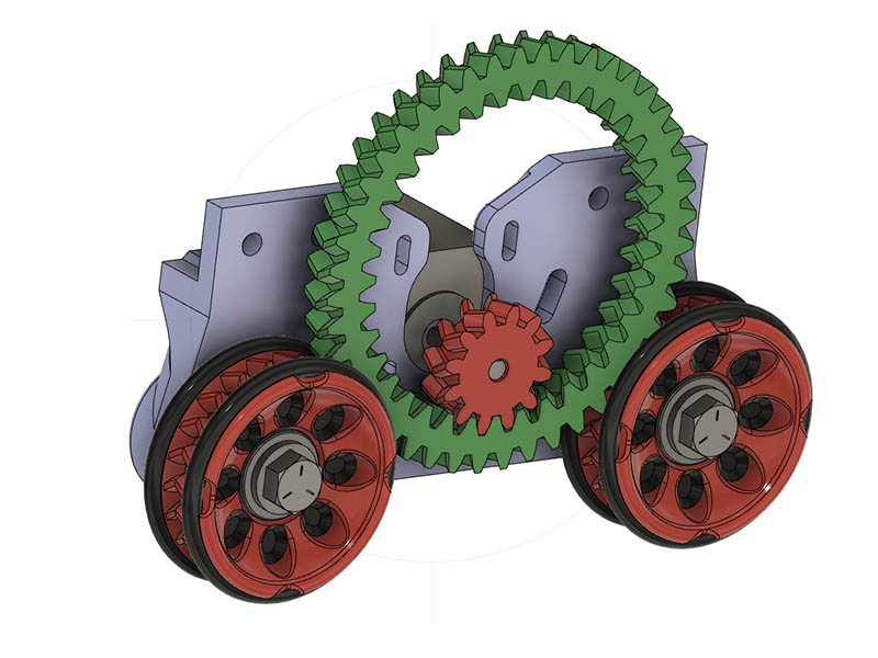
I just couldn’t figure out what you meant by driving that one gear at first. Is this more like what you were saying? It is kind of interesting looking.
3 Likes
Yes, that’s it exactly!
The ring gear isn’t doing anything for your gear ratio, but hopefully you can run a small enough motor pinion to do what you need.
1 Like
Cool. Maybe I will print a smaller ring of this idea to see how it feels. It reminds me of what a ferris wheel looks like. Would this be called a Ferris Wheel drive?
2 Likes
Looks like a hamster wheel to me 
2 Likes
It does kind of look like that. Maybe I should engrave something running on the side of that drive gear.
2 Likes