Roast my table before I build it?

I have my lowrider 3 on a rather precarious table build based off Doug’s remix of Ryan’s parametric table. Although I finally have the CNC running, it doesn’t have legs and since the torsion box itself is a tiny bit crooked, I decided to build a new one from scratch, taking advantage of the larger form factor of MDF boards that I have access to (2750x1830mm) to ditch the holes in the sides and create a simpler build. Inspired in their designs, I modeled the following table. I’d hate to make newbie mistakes, so I’m posting this here to catch any important errors/potential improvements

Summary:
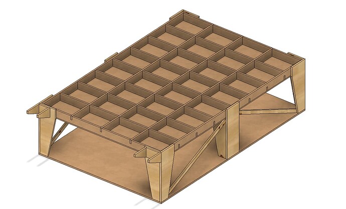
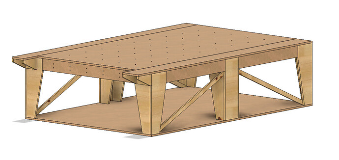
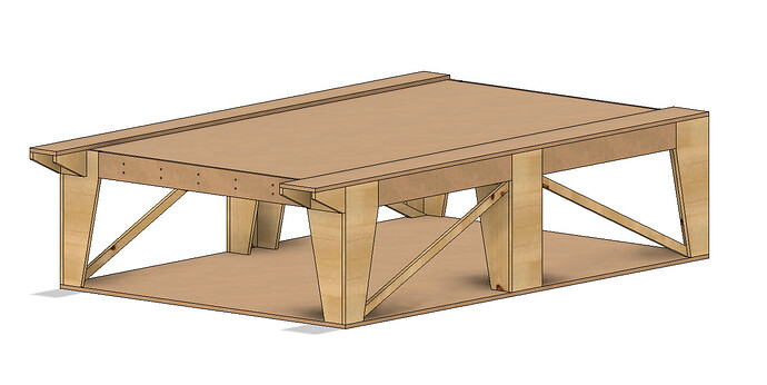
The core of the table is a 4x8 torsion box with notched ribs made out of 18mm (3/4 inch) MDF, with both the top and bottom skirts being 12mm MDF. It’s supported around the corners and in the middle of the longest sides by plywood legs and has diagonal braces laterally. On top of the torsion box sit 3 elements: the spoilboard with t-nuts and two long strips along which the gantry rolls. It’s super similar to the original table except it does not have the “wings” as sliders and can have the sliders be made out of a single piece of wood. Below everything is a tray that will be were I store material and boards. The front side panel of the table also has t-nuts so that I can mill things vertically as well in the little space that is available. Below the bottom tray (and not in CAD yet) sit 4 spring loaded wheels so that the table can accomodate to any imperfections in the floor, which in my case might not be so subtle.

My requirements

  • full 4x8 work area
  • storage for boards
  • sturdy and flat
  • easty to replace spoilboard
  • gantry sliders made out of one single piece
  • spoilboard with holes for clamps and/or dog holes

Doubts

  • Are diagonal braces necessary? If so, do I need another one for the short side as well?
  • how many short and long ribs are necessary for the torsion box? is there a maximum recommended separation?
  • Are these legs ok?
  • Is this build reasonable?

A few photos


All of this is done in a parametric F360 file, so happy to share if it interests anyone. Thanks in advance!
2 Likes

Any particular reason you’re using 18mm for the ribs? The rigidity of the torsion box comes from those members being stressed in their ‘wide’ plane, not across their thickness. The thickness only prevents the members from bowing/buckling under those loads.

Personally, I would make the ribs thinner to cut weight/cost and then consider adding a bottom skin of something super thin which should do way more for rigidity than thickening the ribs.

3 Likes

In the original post someone said they’d built it with 15mm and recommended 18mm plus @DougJoseph 's design I initially made is also 18mm, but what you say makes total sense. It is also true that @vicious1 's original table is made out of 12mm MDF. I’m tempted to use 12mm but it would suck so hard if it did not work as well.

1 Like

Mine is all half inch osb flooring material.

3 Likes

That’s a pretty good choice, frankly. Ryan’s a darn good designer so that should tell you more than a little about what’s needed.

2 Likes

I’d grab some scraps and try to do a scale test. My reasoning is that you can break down the support provided by each rib into one dimension and one part of the table. If your table is 1.8m wide then each ‘pocket’ is roughly 450mm and the middle rib is supporting about 450mm of the weight that’s on the table. Assuming 18mm MDF is 12kg/m^2 and you’ve got 3 layers of it (top surface, spoilboard, workpiece) then that’s 36kg/m^2. Over the 3m long rib at 0.5m wide, that rib is supporting 50kg distributed along. If you cut a single strip of 12mm, clamped it to some blocks at the 2 ends so that it’s vertical and spaced off the ground, you should be able to put 20-30kg of force in the middle and look at how it deflects. That’s probably an order of magnitude worse than the actual load the table will see…

I think most people dramatically overbuild torsion boxes. There’s honestly just not actually that much force involved in any of this, even if you’re loading up slabs to be surfaced! Especially not as you add more and more legs, too.

The other thing I’d say is that if it does end up bowed, that’s just a case of adding another leg in the center to take some load etc. I would very much be approaching this from the perspective of not overbuilding it and instead planning to adjust as I went if it didn’t work out perfect.

1 Like

Torsion boxes are interesting, and can be surprisingly rigid even if the inner ribs and spars are quite lightweight and thin, provided there are lots of them (closely repeated pattern), and rigid even if the skins are quite thin. Think about a hollow core door. So lightweight, yet amazingly strong. Many of the lightweight hollow core doors have ribs and spars made of corrugated board (literally). I suppose if you have a choice between “few” massive, thick ribs and spars versus “lots and lots” of lightweight, thin ribs and spars, you could choose the latter, and save money. However, professional CNC machines are benefited in some ways by having lots of mass. A heavyweight table can better resist vibrations / resonance issues. One consideration is how much weight in sheet goods and contents to be assembled. This would impact how sturdy the legs are, and how many of them there are. I am definitely not an engineer. The first table I made for my LowRider was built without having any CNC machine such as a LowRider, and was the most challenging, hardest woodworking project I had ever undertaken, and while I was pleased at first, I quickly grew frustrated with it. Since rebuilding it and adding a new torsion box to the top, I’ve been much happier.

I just went through and had a read of some resources to remind myself how the beam deflection calculations work etc. Basically the torsion box is just a bunch of beams in X and Y and then with the skins keeping them aligned so we don’t need to consider buckling of the beam elements, etc. In simple terms, I just think about it as a simply supported beam and ignore any middle legs etc.

The deflection of a beam is inversely proportional to the moment of inertia of the beam. The moment of inertia of a simple rectangular beam is (width * height^3)/12. So if you double the thickness of wood you’re using, you halve the deflection for a given load. That makes intrinsic sense, if it’s twice as wide in simple terms it takes twice as much load to deflect it the same. The other part is that the MoI increases with the cube of the height, so a 200mm tall rib has 8x less deflection than a 100mm tall rib. Another thing is that all the beams in one direction can be considered the same for the deflection calculation. It doesn’t matter that they’re spaced apart because we’re only considering force that’s bearing ‘down’ on them, nothing sideways.

So if you’re trying to halve the deflection of a design you can double the thickness of the ribs, add twice as many ribs (effectively the same thing, on a ‘whole system’ basis) or increase the height of the ribs by 26% (because 1.26^3 = 2).

Of course, this only works if everything is supported such that the ribs can’t buckle, etc. but fundamentally using 18mm wide ribs at 100mm tall is as stiff as using 12mm wide ribs at 110mm tall and on and on. In theory, you could use 3mm ribs at ~200mm tall and be just as stiff, but at some point you’ve gotta be able to actually attach stuff to them to keep them all in place and transfer the stress from the skin into the ribs!

The other thing is that the deflection goes up by the cube of the span, too. So if you support a 3m long beam at each end, you’ll have 8x the deflection than if it was supported in 3 points, like with your side legs.

Trying to do a deflection calculation on a 12mm thick, 200mm tall single rib assuming 1.8m of span and a load of ~100kg all up on the table (skin, spoilboard, stock, clamps etc.) supported by 8 ribs I get less than 1mm of deflection.

Another thought is that you’ve said you’ll put sprung wheels on the table. I don’t think I’d do that. I’d personally add fixed castors for movement and then plan to chock/block the table up and into position for the situations where I wanted it perfectly flat/level and wasn’t going to move it for a bit. If you stuck a block in each foot with a bolt, I think you could make leveling feet with a bolt and some scraps pretty easily and get it all leveled up/flat with not much work.

Edit: I also probably wouldn’t go 18mm on the top unless you’re planning on not using a spoilboard at all. The top is only there to stop the ribs moving and to support the material in between the ribs. Think about how stiff a 300x300 piece of 12mm MDF is, that’s basically what each ‘cell’ of your table is. I would way rather make the top surface thinner/lighter/cheaper.

The whole goal of the torsion box approach is to use physics to your advantage to make something stiff and light. If you’re not going to move it ever, I’d be planning for more feet and levelling/chocking it into place. If you’re going to move it all the time, I’d be trying to make it as light as possible. 200kg of MDF isn’t going to be fun to drag around, nor particular cheap, either!

4 Likes

Brilliant answer, spot on. Are the resources you went through publicly available? I’d love to give them a read, seems interesting!

This has convinced me to go for taller 12mm ribs, as indeed I get much more bang for my buck in terms of rigidity if the weight is distributed vertically rather than horizontally. So now everything in the torsion box would be 12mm, including the skirts (which I might make 9mm tbh) and the spoilboard + legs would be 18mm

As for the legs, leveling feet was indeed another option I considered, but I’m curious as to why you think sprung wheels are a bad idea. To me, although a bit more expensive, it seems that they would naturally conform to the floor and keep the tension on the table almost uniform across all contact points.

I would also definitely put a leg in the middle, but that would prevent me from storing full sheets in the bottom tray which is a nice addition imo

I remember watching some Youtuber destructive test an Ikea Linnmon desktop. It took an impressive amount of weight to make the dssktop sag, and definitely deliberately destructive force to break it.

Recall that Ikeaboard like the Linnmon is basically 3mm hardboard outer surface with more or less corrugated cardboard inside in the form of a torsion box, and not even heavy cardboard, more like thick paper.

By contrast, it doesn’t take much to make a torsion box more than strong enough for our purposes.

If you were to make the internal structure from 1/4" MDF, with a 12" square structure, about 3" thick, and glue it to a top and bottom surface of 1/2" MDF, I would trust that to hold my weight.

1 Like

My Torsion box has 18mm ribs, 18mm top and 9mm bottom (granted, that’s a bit more) but I always have to get up the table if I need to change something in the back because it is in a corner. I weigh ~85kgs and that thing does not complain at all.

Cool! Do you mind sharing the size of your table and the height? I’m not necessarily worried about it complaining but rather slightly warping

I’m thinking something like this with slightly wider internal structure and a bit thicker since height adds linearly to weight but cubically to stability.

I basically just winged it, but here is a picture of the build (it has pipes in it for a vacuum table). You can see the full table later on. :slight_smile: It also holds babies pretty well.

1 Like

“Roasting” is done in the BBQ thread.

2 Likes

Super cool. That’s one young engineer :). How’s the vacuum table? Would you build it again or would you stick to nuts and clamps? I have it on my bucket list but as a long term project as I don’t think it’s justified now

:eyes:

I need one of those…

1 Like

If you want to nitpick, it’s “only” a suction table (but yeah, I said vacuum table…). I have it hooked up to a sidechannel blower and it works great if

  • the spoilboard is still flat (mine has got maaany grooves in it),
  • the board you want to work with is flat (they basically never are, Hornbach’s wood is too shitty),
  • you cover the entire area.

It’s a really fun party trick to show your friends if it works. Put a 1200mmx800mm piece of wood on it (that’s the size of the table), turn it on and ask them to move it (not lift). They can’t.
Besides that I have used it like, twice, because of the above reasons. I don’t know whether I’d build one again. It was fun to try (I did a smaller one for the Primo before in MDF, that was a desaster suction-wise…) and if it works it’s great. But the practical usage is low. Just screw that stuff down. :smiley:

Side note: I also tried screw-in nuts, wasn’t so practical. T-tracks didn’t blow me away either. Screws just work. :smiley:

2 Likes

I just need something that holds well….suction or vacuum is fine, if it works…

I need to cut some 6mm EVA foam sheet. Screws don’t work.

My ideal world is a suction table that works.

Even blue tape and glue is a pain because the backing on the foam has some layer that pretty much nothing will stick to

3 Likes

This is the beam deflection calculator I used, it’s just the first one that I found. I couldn’t remember the actual formula and from memory it’s annoying with a distributed load anyway.

I can’t remember what I used for the area moment of inertia formula for the rectangular beam, but this resource describes it pretty well:

That has a couple of nice examples as well as going into how the calculation is derived, if you’re interested.

It’s actually a really interesting process going through and looking at the moments of inertia for an I beam in X and Y. When you first look at one you kinda go ‘sure, I guess…’, then if you get shown the stress vs strain plots on them you can see where they’re coming from and go ‘ok, I see why it’s that shape…’, then if you go further and calculate the area moment of inertia and polar moment of inertia, you can see the tradeoffs between having wider flanges, thicker flanges, taller web, thicker web etc.
Area Moment of Inertia - Typical Cross Sections I has the formulas for an I-beam directly.

Another useful thing for this is looking at stiffness/deflection in a for a tube, given that this is one of the core structural components of these machines. The moment of inertia for a tube is proportional to the OD^4 - the ID^4, so when the walls are thin there are huge gains to be made in stiffness by increasing the wall thickness, but those gains drop rapidly until the difference between a hollow tube and a solid bar is mostly irrelevant. Again, that matches up with the stress/strain example of the I-beam, under deflection the outside parts of the section are being placed in tension/compression while the inside just kinda exists, doing nothing. The other thing there is that as the tube increases in wall thickness, the weight increases. Given that the weight of the tubes is a significant amount of the load on the system causing deflection, there’s a minimum deflection point for a bare tube that’s actually at a relatively thin wall. Doubling the wall thickness almost doubles the weight but will never increase the stiffness by the same amount. In theory, the least deflection for just the tube is always with the thinnest wall, but that changes as soon as we also want to support something mid-span, then eventually there’s a local minima.

As for the comment about the sprung castors, I think they’re a good idea in theory, but ultimately they make the entire surface sprung and mean that you’ve got different loads on different feet. I’d say it’s better than just having solid legs with no adjustment but worse than adjusting the legs to suit. Great for if you’re going to be pushing the table around a lot. Probably not so great for actually using the table itself. I vaguely remember seeing videos of people advising against doing this but I don’t have any personal experience it so I stand to be corrected.

3 Likes

It does work, EVA is flat, if your table is as well you are good. :slightly_smiling_face:

2 Likes