Hello MPCNC Team,
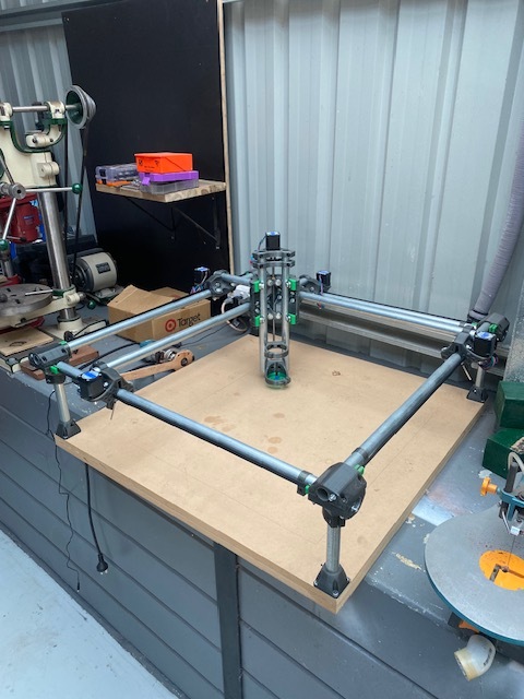
I have put together a MPCNC Burly with a planned work area of 600x600mm.
I’ve almost completed building the machine, with only tensioning the belts and mounting my Makita into its cradle.
I have come to the part where I need to set up this thing’s brain.
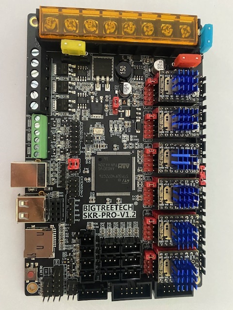
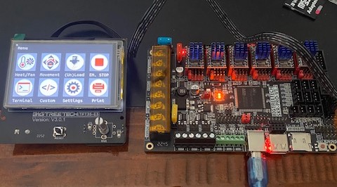
Based on the website information and the fact that the original builder/designer has selected these boards for his online store and made mention of the selection, I have bought the Big Tree Tech SKR Pro 1.2 with TMC 2209 drivers and the TFT35-E3 V3. I wasn’t able to buy from the V1 store.
I have been following the makers instructions quite closely throughout the project and have come to a point where wiring the SKR and the TFT boards together and “flashing the board” has me a bit confused.
Working down the page (for setting up SKR) has pictures showing grey wiring and black wiring both plugged into the board but it the page says I can choose one or the other? or am I misinterpreting this?
When I go to the “Pre configured files” I see a substantial list of several types of boards. By the instructions I believe the one I want is “V1CNC_SkrPro_Dual_2209_2.1.1” I Download that Zip file and ensure I have a FAT32 Formatted blank SD ready in my card reader. I unzip that file to find a zipped version of Marlin and a “firmware.bin” file. Now I am stuck… do I just copy that “firmware.bin” file over to the SD card and then eject the SD from my computer to put into the SKR’s card reader and power it up?
the instructions says not to have the TFT plugged in when I flash the board and then says to flash the screen… so I am guessing here: do I follow the same process of copy the file from the list onto my formatted SD, plug the TFT screen to the SKR board and then the SD card into the screens SD slot and power up?
if anyone would walk me through or has the will to write a dot point instruction sorting out my boards so I can go plug it into my machine I would be extremely grateful.
1/ The tft screen has two possible modes. The touch screen mode uses the 5 wire black cable to talk to the SKR over a serial connection, the display generates the commands you select and sends them to the SKR. Then there is ‘marlin mode’ which uses the two grey cables, this is not touch screen and the display just acts as a single input switch and scrolling menus like the legacy displays. You can use either mode with the relevant cables connected, or fit both sets of cables and switch between modes if you like.
2/ yes place the firmware.bin file in the sdcard root, insert it and switch on. After a few seconds you can remove the sdcard and check it in your computer to ensure the firmware.bin file has been renamed to firmware.cur - that means flashing has been successful.
3/ yes. almost… you should also include the tft35 folder (which contains a fonts and an icons folder) and the config.ini file with the firmware.bin file in the root of the sd card for the screen. That is the normal procedure for flashing these devices, I can’t imagine the V1 firmware is any different.
V1 has a help page on flashing both the SKR and the TFT here
That’s a Primo. The Burly was a previous version looks a little different not quite as good.
The grey cables are for “Marlin Mode” where the TFT acts like a 12864 discount controller, the black is for touch screen mode. If you plug both in, then either mode will work, and you can switch between them. If you choose one or the other, then only that mode will work.
Yes. The “trick” is that it must be a microSD card that goes in the SKR Pro board and not in the SD card slot in the TFT.
There is also a firmware repository for the TFT whi h works in a similar manner, but this would be an SD card that goes into the TFT and not the SKR Pro.
The TFT firmware (for CNC) is In this package unzip the contents so that they are in the root of the drive (there are many files) making sure that the files config.ini and all the .bin files are on the root of the SD card. Put that in the TFT Sd card slot and it will flash when you power up.
Thank you Doug… getting there mate. My main problem with this build is the programming and using the control boards. I simply don’t know… yet. I just need to take those staggering steps to learn it and with the help of the good folks on here like yourself I’ll pick it up all that much faster I am sure.
Most of us find this stuff highly confusing and frustrating! AFAIK there is not a perfect cnc profile for the ‘touchscreen’ mode on these displays… many have tried -
It is not an easy task, there are many interconnecting functions so be warned…it is a very deep and very wide rabbit hole! and AFAIK what you currently have is what V1 supports.
Thanks Mike,
the x2 links are a good read thank you mate.
From the first link you sent and my gleaning from your reply to the OP it would seem that without knowing how to change the functions over to be CNC specific that I am sitting on a very specific creek without said paddle.
The second link had some links that I will have a go with now.
Again Mike, Thanks very much for your kind help mate… worth your weight in gold.
So I’ve been using the second link in @dart1280 last reply to me.
I see what he is saying about rabbit holes…
So far I think I have re-flashed the TFT about 20 odd times with only 1 version mentioning actual spindle CNC on the screen and it wasn’t what I was after.
I hadn’t realised there is such a large following to Laser CNC.
I read a bunch of comments by @jeffeb3, it seemed like he was saying that the firmware available from the link on the V1 website has minor changes to the programming to let it be used with a spindle MPCNC CNC Or do I have that wrong?
A gentleman called @dlopeman was doing some smashing work toward achieving his own version of Firmware until another user completely shut down his mojo. I would have liked to see where he was going with it.
I wonder if anyone out there has a TFT.zip file they can point me at that will give me a simple router CNC dashboard?
The changes for CNC have been pulled into the main distribution, but of course the primary aim of the TFT is for 3D printing. The result is that it now very much looks like a 3D printer interface, and we mostly sqyint a little and pretend that “Print” really means “Cut”.
Maybe somebody could go through and re-make the icons so that it looks more reasonable, and we could package those.
The problem with hacking the firmware is versions. The version that mentioned “spindle” or “laser” was OK, I ran that while I had the LR2 on the SKR Pro. The problem was that BTT updated the hardware and that firmware would have needed to be hacked again from scratch, and.of course, it might happen again.
So, there was a pull request for a change handling the “extruders = 0” case, and now when the firmware gets a new version for possible new hardware, we’ll be OK with just the configuration change to handle it appropriately, and that’s one less thing that V1 has to keep maintained. There was a flurry of posts about the TFTs when the hardware updated and the firmware broke.
The V1 firmware for the TFT does what we need. It isn’t necessarily ideal, because some stuff like temperature manipulation and monitoring isn’t needed for CNC machines in the same way, but the primary functionality that we do need is covered.