Rep Rap Firmware on SKR Pro 1.1 or 1.2

The TFT is looking for a response, but I’m not sure what it sends, or what response it expects. (Probably “ok”.)

Obviously RRF isn’t doing that even if it is listening on the serial port.

I suppose you could.probably use a PanelDue 5i, but it would be nice to use the hardware that you have. I hace been wondering about emulating the PanelDue firmware on the TFT35, at least in terms of its handshaking. I know the PanelDue sends gcode (with line numbers and checksums) and RRF isnt all that picky about what that Gcode is, it will all exexute the same.

I did make up a program for a Raspberry Pi to connect to the PanelDue port on a Duet 2, which would talk to it. I had started on a front end that had a bunch of icons for a touch screen, but I got stalled out and never got much past homing and axis movement, and nothing on starting files.

I kind of wonder if it’s worth digging into the firmware to make a RRF compatable version of the firmware. That would certainly breathe new life into the 2 screens that I have. One is on my Repeat printer, which I want to concert to RRF, abd the other could then be used with another of my Duet 2 boards. I have 2 spare boards. I managed to damage one (ran over the heater wire with the hotend, shorted 24V into a thermistor wire) and fixed that, but I had bought a new board in ln the meantime. Of course as soon as I bought the new board, I found the spare that I had tucked away “somewhere safe”.

Anyway, I am also looking into making the TFT35 talk to RRF, and Ill keep tabs on your progress. If I find an answer before you do, I’ll post it up. I was seeing the same thing. No Printer Attached! Message when connected to RRF, but I could query the board with the terminal.

Ah, so I did a thing…

I hooked the TFT up to an FTI and connected to the computer serial port using Putty.

The TFT sends M105 repeatedly, so it os.looking for a.respomse to that (apparently not “ok”.)

So it is looking for a temperature report, I think.

V1 firmware has the heaters faked to report reasonable temperatures, but if you have no heaters defined, RRF ignores it.

You can define heaters to report MCU and driver temperatures (I do this on the Primo to control a fan over the board.) I think the TFT is expecting the report in Marlin format though, because it doesn’t like my printer board either.

I can see the input from the terminal in Putty, and things like home commands even though it still has the NPA message.

Did you set the screen to extruders: 0? Make sure you are using Ryan’s config.ini

I made two useful rigs for testing the screen. 1) a python script that acted like Marlin, and showed me what was being sent each way. 2) You can split the Tx from the screen and the skr and use two ftdi adapters and see what they are both sending. It is enlightening.

The best reference for a reliable rep rap interface is probably octoprint.

1 Like

This is Ryan’s config.ini with 2 changes.

  1. I changed the serial port configuration to enable the wifi port at 57600baud because I have the ESP01S module in the TFT

  2. I changed the neopixel_pixels parameter from 0 to 4. With it set to zero, I was unable to turn the knob LEDs on. With it set to 4 it works as I expect.

Nothing else in the file was changed. I probably did not need to change the serial port setting because that can be adjusted in the UI.

Anyway, I’m just capturing what it’s sending, and the biggest thing is the M105 every few seconds. Since I checked what my Duet (on my printer) sends back, I know it’s reporting, but the TFT still says NPA. If I touch “home” it sends G28 and M420 (So it still sends it, just suppresses the error message.) Commands entered in the terminal get sent as they are, and it awaits response. I can’t seem to type anything fast enough for it to interpret it as a response though.

I know Octoprint can talk to Marlin or RRF, and I know that this TFT can talk to Marlin. The object of the excercise is to make the TFT talk to RRF. It’s close but not quite there.

I’m learning a few things too about how it does movement.

Going to the move menu doesn’t send anything. Pressing a move button (Say, Y+100) sends G91, M114, then the G0 Y100 F2100

It does not send a G90 until you exit the move menu, so the G91 and M114 are not repeated.
Anyway, it’s fun to play with…

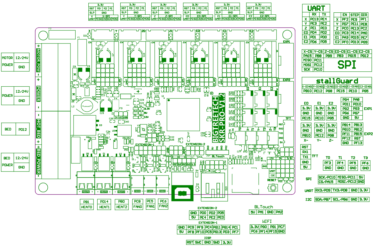
Hmmm. There is a config_rrf.ini in the source tree, which would seem to indicate to me that the firmware should be able to deal with RepRap Firmware. I see the start has a comment to enable the serial port with M574 (Which enables the PanelDue support.)

If it’s just a matter of updating the config.ini…

Maybe you can see what needs to be changed from here:

config_rrf.ini:

#--------------------------------------------------------------------
#
# DEFAULT CONFIG FILE FOR BigTreeTech TFT CONTROLLERS FOR RRF
#
#--------------------------------------------------------------------


#--------------------------------------------------------------------
# Supported TFT Variants
#--------------------------------------------------------------------
#
# BIGTREE_TFT24_V1_1    / BIGTREE_TFT28_V1_0 / BIGTREE_TFT28_V3_0
# BIGTREE_TFT35_V1_0    / BIGTREE_TFT35_V1_1 / BIGTREE_TFT35_V1_2
# BIGTREE_TFT35_V2_0    / BIGTREE_TFT35_V3_0 / BIGTREE_TFT35_E3_V3_0
# BIGTREE_TFT35_B1_V3_0 / BIGTREE_TFT43_V3_0 / BIGTREE_TFT50_V3_0
# BIGTREE_TFT70_V3_0
#
# BIGTREE_GD_TFT24_V1_1    / BIGTREE_GD_TFT35_V2_0    / BIGTREE_GD_TFT35_V3_0
# BIGTREE_GD_TFT35_E3_V3_0 / BIGTREE_GD_TFT35_B1_V3_0 / BIGTREE_GD_TFT43_V3_0
# BIGTREE_GD_TFT50_V3_0    / BIGTREE_GD_TFT70_V3_0
#
# MKS_TFT28_V3_0 / MKS_TFT28_V4_0 / MKS_TFT28_NEW_GENIUS
# MKS_TFT32_V1_3 / MKS_TFT32_V1_4 / MKS_TFT35_V1_0
#
# Firmware source: https://github.com/bigtreetech/BIGTREETECH-TouchScreenFirmware


#--------------------------------------------------------------------
# Supported RepRap Firmware Versions
#--------------------------------------------------------------------
#
# Tested with RepRap firmware version: 3.x
# Firmware source: https://github.com/Duet3D/RepRapFirmware/releases or https://github.com/gloomyandy/RepRapFirmware/releases
#
# To use all the features and functionalities supported by the TFT,
# the following options must be configured in the system files on Duet Web Control.
#
# Config.g Changes
#   Add the following line to your config.g to enable the screen.
#
#   M575 P1 S1 B57600
#
# In case you need help, please visit: https://discord.com/invite/uS97Qs7 or https://teamgloomy.github.io/


#--------------------------------------------------------------------
# General Settings
#--------------------------------------------------------------------

#### Serial Ports (Primary and Supplementary)
# Serial ports connected to devices such as Printer, ESP3D, OctoPrint and other Controllers.
# In order to successfully establish a communication through a serial port, set a baudrate
# matching the baudrate configured on the connected device.
# Disable the serial port when it is not in use and/or not connected to a device (floating) to
# avoid to receive and process wrong data due to possible electromagnetic interference (EMI).
#
# NOTES:
#   - Serial port P1 is the primary serial connection to the printer and cannot be disabled.
#   - A baudrate of 250000 works in most cases, but you can try a lower speed if you
#     commonly experience drop-outs during host printing.
#     You may try up to 1000000 to speed up SD file transfer.
#
#   Format: [serial_port: P1:<baudrate> P2:<baudrate> P3:<baudrate> P4:<baudrate>
#   Target port: P1: Printer
#                P2: WIFI    (e.g. ESP3D)
#                P3: UART 3  (e.g. OctoPrint)
#                P4: UART 4
#   Value range: P1: [min: 1, max: 9]
#                P2: [min: 0, max: 9]
#                P3: [min: 0, max: 9]
#                P4: [min: 0, max: 9]
#   Options: [OFF (port disabled): 0, 2400: 1, 9600: 2, 19200: 3, 38400: 4, 57600: 5, 115200: 6, 250000: 7, 500000: 8, 1000000: 9]
serial_port:P1:5 P2:0 P3:0 P4:0

#### Emulated M600
# The TFT intercepts the M600 G-code (filament change) and emulates the handling logic
# otherwise provided by Marlin firmware.
#
# NOTE: Enable it in case Marlin firmware does not properly support M600 on the mainboard.
#
#   Options: [disable: 0, enable: 1]
emulated_m600:0

#### Emulated M109 And M190
# The TFT intercepts the blocking M109 and M190 G-codes (set target hotend and bed temperatures)
# and converts them to the non-blocking M104 and M140 G-codes respectively.
#
# NOTE: Enable it so the TFT can still communicate with Marlin firmware even if the target
#       temperature is not reached yet. Otherwise the communication (TFT<->Marlin) will be
#       frozen until desired/set temperatures are obtained.
#
#   Options: [disable: 0, enable: 1]
emulated_m109_m190:0

#### Event LED
# When printing from TFT SD card / TFT USB disk, the TFT periodically sets the printer's (neopixel)
# LED color and TFT's knob LED color, if any, according to the current nozzle and bed temperatures.
#
# NOTE: If "emulated_m109_m190" is disabled (heating controlled by printer), the TFT cannot control the
#       printer's (neopixel) LED during heating. It will control only the TFT's knob LED, if any.
#
#   Options: [disable: 0, enable: 1]
event_led:1

#### G-code File Comment Parsing
# The TFT parses and processes extra information provided by the slicer as comments in the G-code file.
# If enabled, the current implementation parses and processes print time and print layer information
# from the G-code file (nothing else).
# If disabled, the "layer_disp_type" setting provided in "UI Settings" section becomes redundant.
#
# NOTE: Enable it in case the slicer (e.g. Cura) supports extra information.
#
#   Options: [disable: 0, enable: 1]
file_comment_parsing:1


#--------------------------------------------------------------------
# UI Settings
#--------------------------------------------------------------------

#### Rotated UI
# Rotate UI by 180 degrees.
#   Options: [disable: 0, enable: 1]
rotated_ui:0

#### Touch Mode Language
# Select the language to use on the LCD while in Touch Mode.
#
# NOTE: To add/flash a second language copy the required "language_xx.ini" file from
#       "Language Packs" folder to the SD root folder.
#       Then press the reset button to load/flash the copied language file.
#
#   Options: [Primary Language (english): 0, Secondary Language: 1]
language:0

#### Status Screen
# Select the default home screen while in Touch Mode.
# If enabled, the Status Screen menu will become the default home screen.
# If disabled, the Main menu will become the default home screen.
#
# NOTE: Both the Status Screen and Main menus display the current temperature, fan and speeds.
#       Furthermore, the Status Screen menu provides the status area reporting the printer notifications.
#
#   Options: [disable: 0, enable: 1]
status_screen:1

#### Touch Mode Colors
# Set colors used in Touch Mode.
#
# NOTE: Select an option from the provided list or set the color (RGB888 format) hex value directly
#       (start with "0x"), such as: Red: 0xFF0000, Green: 0x00FF00, Blue: 0x0000FF.
#
#   Options: [ WHITE: 0,  BLACK: 1,  RED: 2,  GREEN: 3,      BLUE: 4,       CYAN: 5,  MAGENTA: 6,    YELLOW: 7,
#             ORANGE: 8, PURPLE: 9, LIME: 10, BROWN: 11, DARKBLUE: 12, DARKGREEN: 13,    GRAY: 14, DARKGRAY: 15]

## Title background color
title_background_color:1

## Menu background color
menu_background_color:1

## Menu font color
menu_font_color:0

## Reminder font color, such as: "No print attached", "Busy processing", etc.
reminder_font_color:2

## Status (e.g. volume reminder, ABL probing point etc.) font color, such as: "Card inserted", "Card removed"
status_font_color:5

## Background color for X Y Z position display in Status Screen menu
status_xyz_bg_color:15

## List View border color
list_border_color:15

## List View button background color
list_button_bg_color:15

## Color used by the Mesh Editor menu for drawing the mesh with the minimum value in the grid
mesh_min_color:7

## Color used by the Mesh Editor menu for drawing the mesh with the maximum value in the grid
mesh_max_color:2

#### Terminal Text Color Scheme
# Color scheme for displaying text in Terminal menu.
#   Options: [Material Dark: 0, Material Light: 1, High Contrast: 2]
#     Material Dark:  Dark background with light font color and orange command font color.
#     Material Light: Light background with dark font color and orange command font color.
#     High Contrast:  Black background with white font color and orange command font color.
terminal_color_scheme:0

#### Notification Style For ACK Messages
# Set the notification style to use for displaying the ACK messages which start with "echo:".
#
# NOTE: The OFF value is applied to any ACK message type (e.g. even to known echo ACK).
#       It means that any kind of ACK message is silently discarded.
#
#   Options: [OFF: 0, POPUP: 1, TOAST: 2]
#     OFF:   No notification. The message is ignored.
#     POPUP: Display a popup window for user confirmation.
#     TOAST: A non-blocking Toast notification is displayed for few seconds. No user interaction is needed.
ack_notification:1

#### Files Sorting
# Sort files and folders based on the selected option.
#
# NOTE: Only applicable for files in TFT SD card and TFT USB disk.
#
#   Options: [Date Newest First: 0, Date Oldest First: 1, Name Ascending: 2, Name Descending: 3]
files_sort_by:0

#### Files List Mode
# Display files in list mode instead of icon mode.
#   Options: [disable: 0, enable: 1]
files_list_mode:1

#### Filename Extension
# Display fullname for files listed in List Mode / Icon Mode menu.
# If disabled, any filename extension starting with ".g" or ".G" (e.g. ".g", ".gco", ".gcode" etc.) will be hidden.
#   Options: [disable: 0, enable: 1]
filename_extension:1

#### Fan Speed In Percentage
# Show fan speed in percentage. If disabled fan speed will be displayed as PWM values.
#   Options: [disable: 0, enable: 1]
fan_speed_percentage:1

#### Persistent Temperature Info
# Show persistent temperature info in all menus.
#   Options: [disable: 0, enable: 1]
persistent_info:0

#### Temperature And Wait ACK In Terminal
# Show "temperature" and "wait" ACK in Terminal menu.
#   Options: [disable: 0, enable: 1]
terminal_ack:0

#### Notification M117
# If enabled, any notification received from Marlin through "//action:notification" is also
# stored on the notification screen. The notification screen reporting the history of the
# received notifications is displayed pressing on the notification bar.
#
# NOTE: Marlin notifications are also always displayed on the Status Screen menu.
#       Furthermore, they are also displayed on the notification bar as toast messages
#       in case the current menu is not the Status Screen menu.
#
#   Options: [disable: 0, enable: 1]
notification_m117:0

#### Progress Source
# This sets the source of the progress calculation, G-code file advance based mode or time based mode:
# - File mode is a simple file progress, it tells you the percentage of the G-codes executed.
#   It doesn't reflect the amount of work done, only in a very few cases (ex. a 2D shape expanded
#   vertically like a cylinder, cube etc.).
# - Time mode is very close to the real amount of work done, but it is still not perfect and it relies
#   on the estimate the slicer has done (see notes below).
#
# NOTES:
#   - Time mode needs info from the G-code file such as the elapsed time or the remaining time. This info
#     can be supplied as "M73 Rxx" G-code or as comment. Both must be generated by the slicer. If comment
#     is used than "file_comment_parsing" has to be enabled for it to take effect.
#     If that info is missing (comment or "M73 Rxx"), the progress source defaults to option 0 (file mode).
#   - If "M73 Pxx" is present in the G-code file then file or time based progress modes will be overriden
#     by that.
#
#   Options: [File mode: 0, Time mode: 1]
prog_source:1

#### Progress Numeric Display Mode During Print
# This sets the default display type for print progress numeric display. It can be changed during
# print by pressing the hourglass icon. At each click it will alter between the 3 variants.
#
# NOTE: It needs info from the G-code file such as the elapsed time or the remaining time. This info can
#       be supplied as "M73 Rxx" G-code or as comment. Both must be generated by the slicer. If comment
#       is used than "file_comment_parsing" has to be enabled for it to take effect.
#       If that info is missing (comment or "M73 Rxx"), the display defaults to option 0 (percentage &
#       elapsed time).
#
#   Options: [Percentage & Elapsed time: 0, Percentage & Remaining time: 1, Elapsed time & Remaining time: 2]
prog_disp_type:2

#### Current Layer Display Mode During Print
# This sets the default display type for the printing layer. It can be changed during print by
# pressing the nozzle icon. At each click it will alter between the 3 variants.
#
# NOTES:
#   - It requires "file_comment_parsing" to be enabled.
#   - This feature uses the layer number comments added by slicers at the starting of each layer.
#   - Some slicers may not include the total number of layers in the G-code file. In this case only
#     the current layer will be displayed. To display total number of layers, a comment should be
#     added at the beginning of the G-code file in the format "; Layer count: xx".
#     Separators can be " ", ":", "_" or "=".
#   - If the total number of layers exceeds 999, this information will not be displayed because
#     there is not enough space for both current and total layer number to be shown.
#   - If PrusaSlicer is used, to enable the layer number display, the following comment lines must
#     be added in Printer Settings -> Custom G-code section:
#     - In After layer change G-code section:
#       ";LAYER:[layer_num]"
#     - In Start G-code section:
#       ";LAYER_COUNT:[total_layer_count]"
#
#   Options: [Layer height: 0, Layer number: 1, Both - height & number: 2]
layer_disp_type:0


#--------------------------------------------------------------------
# Marlin Mode Settings (only for TFT24 V1.1 & TFT28/TFT35/TFT43/TFT50/TFT70 V3.0)
#--------------------------------------------------------------------

#### Default Mode
# Set Marlin/Touch Mode as the default mode at startup.
#
# NOTE: Mode switching is possible only for Marlin Mode and Touch Mode by a long press of
#       1.5 seconds on the display or holding down the encoder button for 1.5 seconds.
#
#   Options: [Marlin Mode: 0, Touch Mode: 1, Blocked Marlin Mode: 2, Blocked Touch Mode: 3]
default_mode:1

#### Serial Always ON
# Keep UART (serial communication) alive in Marlin Mode.
# Allows seamless OctoPrint UART connection to the TFT's UART/serial expansion port
# no matter which mode the TFT is in.
#   Options: [disable: 0, enable: 1]
serial_always_on:1

#### Marlin Mode Background & Font Colors
# Set colors used in Marlin Mode.
#
# NOTE: Select an option from the provided list or set the color (RGB888 format) hex value directly
#       (start with "0x"), such as: Red: 0xFF0000, Green: 0x00FF00, Blue: 0x0000FF.
#
#   Options: [ WHITE: 0,  BLACK: 1,  RED: 2,  GREEN: 3,      BLUE: 4,       CYAN: 5,  MAGENTA: 6,    YELLOW: 7,
#             ORANGE: 8, PURPLE: 9, LIME: 10, BROWN: 11, DARKBLUE: 12, DARKGREEN: 13,    GRAY: 14, DARKGRAY: 15]

## Marlin Mode background color
marlin_background_color:1

## Marlin Mode font color
marlin_font_color:8

#### Fullscreen Marlin Mode
# Run Marlin Mode in fullscreen.
#
# NOTE: Disable is recommended for TFT24.
#
#   Options: [disable: 0, enable: 1]
marlin_fullscreen:0

#### Show Marlin Mode Title
# Show banner text at the top of the TFT in Marlin Mode.
#   Options: [disable: 0, enable: 1]
marlin_show_title:0

#### Marlin Mode Title
# Banner text displayed at the top of the TFT in Marlin Mode.
#   Value range: [min: 3, max: 20 characters]
marlin_title:Marlin Mode

#### Marlin Mode Type
# Select Marlin Mode type.
#   Options: [128x64 Full Graphic LCD: 0, 20x4 Character LCD: 1]
marlin_type:0


#--------------------------------------------------------------------
# Printer / Machine Settings
#--------------------------------------------------------------------

#### Hotend Count
#   Value range: [min: 0, max: 6]
hotend_count:1

#### Heated Bed Support
# Enable/disable presence of heated bed.
#
# NOTE: Disable it to let the TFT auto-detect if bed heating is enabled in Marlin firmware.
#
#   Options: [disable: 0, enable: 1]
heated_bed:1

#### Heated Chamber Support
# Enable/disable presence of heated chamber.
#
# NOTE: Disable it to let the TFT auto-detect if chamber heating is enabled in Marlin firmware.
#
#   Options: [disable: 0, enable: 1]
heated_chamber:0

#### Extruder Count
# Set extruder count.
#
# NOTE: This value is overridden by the TFT if provided by Marlin firmware.
#
#   Value range: [min: 0, max: 6]
ext_count:1

#### Fan Count
#   Value range: [min: 1, max: 6]
fan_count:1

#### Controller Fan Support
# Enable/disable controller fan speed control for Active and Idle cooling if Marlin
# firmware supports controller fan (M710).
#   Options: [disable: 0, enable: 1]
controller_fan:0

#### Bed / Extruder / Chamber Maximum Temperatures
#   Format: [max_temp: T0:<max temp> T1:<max temp> T2:<max temp> T3:<max temp> T4:<max temp> T5:<max temp> BED:<max temp> CHAMBER:<max temp>]
#   Unit: [temperature in °C]
#   Value range: hotend:  [min: 20, max: 1000]
#                bed:     [min: 20, max: 400]
#                chamber: [min: 20, max: 200]
max_temp:T0:275 T1:275 T2:275 T3:275 T4:275 T5:275 BED:150 CHAMBER:60

#### Cold Extrusion Minimum Temperature
# Minimum temperature needed to extrude/retract.
# Any extrusion/retraction below this temperature will be prevented.
#   Unit: [temperature in °C]
#   Value range: [min: 20, max: 1000]
min_temp:180

#### Fan Maximum PWM Speed
# Set minimum and maximum fan speed allowed by the printer for Cooling Fans & Controller Fan.
# Cooling fans have index from F0 to F5.
# Controller fan has index CtA and CtI (Active and Idle). It requires "controller_fan" to be enabled.
#   Format: [fan_max: F0:<max PWM> F1:<max PWM> F2:<max PWM> F3:<max PWM> F4:<max PWM> F5:<max PWM> CtA:<max PWM> CtI:<max PWM>]
#   Unit: [PWM]
#   Value range: [min: 25, max: 255]
fan_max:F0:255 F1:255 F2:255 F3:255 F4:255 F5:255 CtA:255 CtI:255

#### Machine Size / Build Area
# The TFT will auto-detect the machine size (min and max) in Marlin firmware (requires
# enabling "M115_GEOMETRY_REPORT" in Configuration_adv.h in Marlin firmware).
#   Format: [size_min: X<minimum distance> Y<minimum distance> Z<minimum distance>]
#           [size_max: X<maximum distance> Y<maximum distance> Z<maximum distance>]
#   Unit: [distance in mm]
#   Value range: [min: -2000, max: 2000]
size_min:X0 Y0 Z0
size_max:X235 Y235 Z250

#### X & Y Move Speeds/Feedrates
# Move speeds used in Move menu to move X and Y axes.
#   Format: [move_speed: S<feedrate> N<feedrate> F<feedrate>]
#   Unit: [feedrate in mm/min]
#   Value range: [min: 10, max: 12000]
xy_speed:S1000 N3000 F5000

#### Z Speeds/Feedrates
# Move speeds used in Move menu to move Z axis.
#   Format: [move_speed: S<feedrate> N<feedrate> F<feedrate>]
#   Unit: [feedrate in mm/min]
#   Value range: [min: 10, max: 12000]
z_speed:S500 N1000 F2000

#### Extruder Speeds/Feedrates
# Speed settings used to extrude/retract.
#   Format: [ext_speed: S<feedrate> N<feedrate> F<feedrate>]
#   Unit: [feedrate in mm/min]
#   Value range: [min: 10, max: 12000]
ext_speed:S60 N600 F1200

#### Auto Load Bed Leveling Data
# If enabled, load bed leveling data and turn leveling on at startup sending gcode "M420 S1".
#
# NOTE: If enabled, it is required:
#       1) EEPROM and a bed leveling type (e.g. UBL) enabled in Marlin.
#       2) A valid mesh saved on EEPROM (it is required to enable bed leveling).
#          If the mesh is invalid / incomplete leveling will not be enabled.
#
#   Options: [disable: 0, enable: 1]
auto_load_leveling:0

#### Onboard / Printer Media Support
# Enable/disable presence of onboard media.
#
# NOTE: Auto-detect option is currently available (supported) by Marlin firmware.
#       Auto-detect is not available for other firmwares like Smoothieware.
#
#   Options: [disable: 0, enable: 1, auto-detect: 2]
onboard_sd:1

#### M27 Printing Status Refresh Time
# M27 printing status refresh time (this will be used if SD_AUTOREPORT is not detected by the TFT).
#   Unit: [time in seconds]
#   Value range: [min: 1, max: 100]
M27_refresh_time:3

#### M27 Always Active
# Keep polling M27 even if not printing (e.g. SD print not started from TFT).
#   Options: [disable: 0, enable: 1]
M27_always_active:0

#### Long File Names Support
# Enable/disable support to long file names.
#
# NOTE: Auto-detect option is currently available (supported) by Marlin firmware.
#       Auto-detect is not available for other firmwares like Smoothieware.
#
#   Options: [disable: 0, enable: 1, auto-detect: 2]
long_filename:2

#### Pause/Nozzle Park Settings
# These settings are used when a print is paused or in any feature which requires moving/parking the nozzle
# before performing a task like in (Un)Load or Extruder Tuning menus.

## Pause Retract Length
#   Format: [pause_retract: R<retract length> P<resume purge length>]
#   Unit: [length in mm]
#   Value range: [min: 0.0, max: 20.0]
pause_retract:R15.0 P16.0

## Pause XY Position
# NOTES:
#   - It MUST BE a value >= 0 for a Cartesian printer.
#   - It MUST BE a value <= 0 for a Delta printer.
#
#   Format: [pause_pos: X<position> Y<position>]
#   Unit: [position in mm]
#   Value range: [min: -2000.0, max: 2000.0]
pause_pos:X10.0 Y10.0

## Pause Z Raise
# Raise Z axis by this value relative to the current layer height.
#   Unit: [distance in mm]
#   Value range: [min: 0.0, max: 2000.0]
pause_z_raise:10.0

## Pause Feed Rate
# Feedrate to use when moving an axis when printing is paused.
#   Format: [pause_feedrate: XY<feedrate> Z<feedrate> E<feedrate>]
#   Unit: [feedrate in mm/min]
#   Value range: [min: 10, max: 12000]
pause_feedrate:XY6000 Z6000 E600

#### Leveling Settings
# These settings are used for leveling.

## Leveling Edge Distance (Manual Leveling, Leveling Corner)
# Inset distance from bed edges. This distance is added to minimum X & Y bed coordinates and
# subtracted from maximum X & Y bed coordinates to calculate manual leveling points.
# For Leveling Corner, the default distance is the maximum between this setting value and
# the rounded probe offset X/Y values configured in Marlin firmware.
#   Unit: [distance in mm]
#   Value range: [min: 0, max: 2000]
level_edge_distance:20

## Leveling Z Position (Manual Leveling, Leveling Corner, Mesh Leveling, Probe/Home Offset, Mesh Tuner)
# For Manual Leveling and MBL, lower Z axis to this absolute position after reaching a leveling point.
# For Probe/Home Offset and ABL in Mesh Tuner, raise Z axis by this relative position after reaching
# a leveling point.
#   Unit: [position in mm]
#   Value range: [min: 0.0, max: 2000.0]
level_z_pos:0.2

## Leveling Z Raise (Manual Leveling, Leveling Corner, Mesh Leveling)
# Raise Z axis by this relative value before moving to another point during leveling/probing procedures.
#   Unit: [distance in mm]
#   Value range: [min: 0.0, max: 2000.0]
level_z_raise:10.0

## Leveling Feed Rate (Manual Leveling, Leveling Corner, Mesh Leveling)
# Feedrate to use when moving an axis during leveling/probing procedures.
#   Format: [level_feedrate: XY<feedrate> Z<feedrate>]
#   Unit: [feedrate in mm/min]
#   Value range: [min: 10, max: 12000]
level_feedrate:XY6000 Z6000

#### Inverted Axes (Manual Leveling, Leveling Corner, Move, Probe Offset)
# Used by Manual Leveling, Leveling Corner, Move and Probe Offset menus in order axis matches the actual axis movement.
#
# NOTE: The Y axis of different printer (move hotbed or move nozzle) move in different directions.
#       So Y axis leveling inversion can't follow up inverted_axis[Y_AXIS].
#       We separate a single variable "LY" (Leveling Y axis) to deal with the Y axis leveling movement direction.
#
#   Format: [X<option> Y<option> Z<option> LY<option>]
#   Options: [disable: 0, enable: 1]
inverted_axis:X0 Y0 Z0 LY0

#### Probing For Z Offset (Probe Offset)
# Used by the Probe Offset menu for the Z offset tuning process.
# If enabled, after homing a probing in the center of the bed is performed and then the nozzle
# is moved to the XY probing point.
# If disabled, after homing the nozzle is moved directly to the XY homing point. This is useful
# in case Marlin firmware is configured to use the probe for Z axis homing (e.g.
# USE_PROBE_FOR_Z_HOMING enabled in Marlin firmware) to avoid a second probing after homing.
#
# NOTES:
#   - Enable it in case Marlin firmware is not configured to use the probe for Z axis homing
#     (e.g. USE_PROBE_FOR_Z_HOMING disabled in Marlin firmware) or the XY probing point set
#     for homing is not reachable by the nozzle (e.g. due to HW limitations/constraints or
#     printer specific configuration).
#   - Disable it (preferably) in case Marlin firmware is configured to use the probe for Z axis
#     homing (e.g. USE_PROBE_FOR_Z_HOMING enabled in Marlin firmware).
#
#   Options: [disable: 0, enable: 1]
probing_z_offset:1

#### Probing Z Raise (Probe Offset, Mesh Editor)
# Used by the Probe Offset / Mesh Editor menu for the Z offset / Z height tuning process.
# Raise / drop Z axis by this relative value after homing (G28) before starting to probe a point.
#
# NOTES:
#   - It MUST BE a value >= 0 (e.g. 20) for a Cartesian printer to avoid crashing into the bed.
#   - It MUST BE a value <= 0 (e.g. -50) for a Delta printer to avoid crashing into the top of the tower.
#
#   Unit: [distance in mm]
#   Value range: [min: -2000.0, max: 2000.0]
probing_z_raise:20.0

#### Z Steppers Auto-Alignment (ABL)
# It allows to align multiple Z stepper motors using a bed probe by probing one position per stepper.
# Enable this setting to show an icon in ABL menu allowing to run G34 command (it requires
# Z_STEPPER_AUTO_ALIGN enabled in Configuration_adv.h in Marlin firmware).
#
# NOTE: Only for Marlin printers with one stepper driver per Z stepper motor and no Z timing belt.
#
#   Options: [disable: 0, enable: 1]
z_steppers_alignment:0

#### TouchMI Settings (ABL)
# Enable this option for displaying TouchMI sensor settings in ABL menu (Init, Z Offset, Save, Test).
#   Options: [disable: 0, enable: 1]
touchmi_sensor:0

#### Preheat Temperatures
#   Format: [preheat_name_X:<name>]
#           [preheat_temp_X:T<hotend temp> B<bed temp>]
#   Unit: [temperature in °C]
#   Value range: name:        [min: 3, max: 20 characters]
#                hotend temp: [min: 20, max: 1000]
#                bed temp:    [min: 20, max: 400]
preheat_name_1:PLA
preheat_temp_1:T200 B60

preheat_name_2:PETG
preheat_temp_2:T240 B70

preheat_name_3:ABS
preheat_temp_3:T230 B90

preheat_name_4:WOOD
preheat_temp_4:T170 B50

preheat_name_5:TPU
preheat_temp_5:T220 B50

preheat_name_6:NYLON
preheat_temp_6:T250 B90


#--------------------------------------------------------------------
# Other Device-Specific Settings
#--------------------------------------------------------------------

#### Sounds / Buzzer
# Set sound ON or OFF.
#
# NOTE: Error messages from printer will always play the error sound.
#
# Parameters:
#   touch_sound:  Enable/disable this to control touch feedback sound.
#   toast_sound:  Enable/disable this to control all toast notification sounds.
#   alert_sound:  Enable/disable this to control all popup and alert sounds
#                 like print finish alert, dialog sound etc.
#   heater_sound: Enable/disable this to control acoustic feedback when temperature
#                 has reached the desired value on heaters (nozzle, bed, chamber).
#
#   Options: [disable: 0, enable: 1]
touch_sound:1
toast_sound:1
alert_sound:1
heater_sound:1

#### LCD Brightness Levels (only for TFT28/TFT35/TFT43/TFT50/TFT70 V3.0)
# Brightness levels for LCD.
#   Options: [OFF: 0, 5%: 1, 10%: 2, 20%: 3, 30%: 4, 40%: 5, 50%: 6, 60%: 7, 70%: 8, 80%: 9, 90%: 10, 100%: 11]

## LCD brightness level
lcd_brightness:11

## LCD brightness level when device is idle
lcd_idle_brightness:5

#### LCD Idle Time (only for TFT28/TFT35/TFT43/TFT50/TFT70 V3.0)
# The LCD screen will dim to idle brightness, if the display is not touched for the
# period of the LCD idle time.
#   Options: [OFF: 0, 5sec: 1, 10sec: 2, 30sec: 3, 1min: 4, 2min: 5, 5min: 6, 10min: 7]
lcd_idle_time:4

#### LCD Lock On Idle (only for TFT28/TFT35/TFT43/TFT50/TFT70 V3.0)
# If enabled, when the LCD is idle (dimmed) then the first touch on the display will
# simply restore the normal LCD brightness. The touch is then skipped, preventing to
# trigger any undesired action due to the dimmed display.
#
# NOTE: The lock is always avoided if the LCD brightness is restored by the use of
#       rotary encoder instead of touching the display.
#
#   Options: [disable: 0, enable: 1]
lcd_lock_on_idle:0

#### LED Color
# Printer's LED color used by some features such as Event LED and PID processes.
#   Format: [led_color: R:<component> G:<component> B:<component> W:<component> P:<component> I:<component>
#   Target component: R: Red
#                     G: Green
#                     B: Blue
#                     W: White;     NEOPIXEL or RGB(W)
#                     P: Intensity; NEOPIXEL
#                     I: Index;     NEOPIXEL
#   Value range: [min: 0, max: 255]
led_color:R:255 G:255 B:255 W:255 P:255 I:255

#### LED Always ON
# Keep printers's LED on at startup and after Event LED and PID processes terminate.
# The printer's LED color is configured in "led_color".
#   Options: [disable: 0, enable: 1]
led_always_on:0

#### Knob LED Color (only for TFT28/TFT35_E3/TFT43/TFT50/TFT70 V3.0)
# Knob LED color at startup.
#   Options: [OFF: 0, WHITE: 1, RED: 2, ORANGE: 3, YELLOW: 4, GREEN: 5, BLUE: 6, INDIGO: 7, VIOLET: 8]
knob_led_color:0

#### Knob LED Idle State (only for TFT28/TFT35_E3/TFT43/TFT50/TFT70 V3.0)
# If enabled, when the LCD is idle (dimmed) then the knob LED will be also switched off.
#   Options: [disable: 0, enable: 1]
knob_led_idle:1

#### Knob LED Pixels (only for TFT28/TFT35_E3/TFT43/TFT50/TFT70 V3.0)
# Set the number of LEDs in the strip connected to "Neopixel" port of TFT.
# It shares the same signal line as "knob_led_color". 0 means the default number in TFT hardware.
# Greater than 0 means the number of LEDs in the strip.
#   Value range: [min: 0, max: 200]
neopixel_pixels:0

It works!

Okay, so there are 2 keys to this. One is in the board.txt file in the sys directory. The line:

serial.aux.rxTxPins = { PA_10, PA_9 };

By default this line has those defined as NoPin so it’s turned off.

In the config.g file the line is

M575 P1 S2 B57600                              ; enable support for PanelDue

The default line is S1 instead, but that serial port is taken by the wifi module

My TFT35 is now reporting that it’s connected to a printer, and therefore can do the stuff that the printer can.

I am running the config.ini for RRF up there, and it recognizes the response. It’s still querying temperatures, but since RRF is responding as expected, it seems to work.

2 Likes

That´s great news for you!

I have similar settings since the start of my experiments, but at my end it wont work :frowning:

I can get it to respond to homing & moving using the following settings (obviously also depends on TFT serial baudrate):

M575 P1 S2 B57600
M575 P1 S0 B115200
M575 P1 S2 B250000

But it keeps reporting “NPA”

I used the V1 TFT FW, I tested stock TFT FW with RRF config file, reset the screen fully… nothing works at my end.

My current theorie is that I either need to set and activate a tool, or my serial port on TFT is corrupt.

edit: activating a tool was not the solution. Up to compiling custom TFT FW to set uart 3 as 1

Okay, so let’s see.

I am using the V1 firmware on the TFT, but with the config_rrf.ini renamed to config.ini and put on the root of the SD card (Is now config.ini.cur) I note though that this does have extruders set to 1, you will want it set to 0

On the TFT the serial port is set to 57600 baud.

On the SKR Pro, the board.txt file has been edited. The serial.aux.rxTxPins is already present, but is set to NoPin, and it needs to be set to the UART pins PA_10, PA_9

On the SKR Pro the config.g file has the serial port enabled on port 2, in mode 1 (Raw mode, no line numbers or checksums needed.)

Can you upload your config.g and board.txt file? (I’m out for the next few hours, but I can give them a try and see if I can get them going on my board.

Edit, if you have a serial FTI, you can try connecting to the board over the serial line, as well as connecting to the TFT. that will at least tell you which side isn’t behaving correctly, and if the serial UART is working at all.

So the “No Printer Attached” is driving me nuts.

  • Tried V1 TFT FW, with Marlin config, no luck
  • Tried V1 TFT FW, with RRF config, no luck
  • Recompiled the TFT35 E3 V3 to use another serial port (3) instead of default: no luck
    (used these topics for pointers 1 & 2)
  • Changed baudrate 57,6K ~ 250K, no luck
  • Changed baudrate protocol, no luck

The only thing it does is homing & moving after homing.

The board.txt contains:

// Board Hardware configuration file for SKR Pro
// generated by RepRapFirmware Configuration Tool (LPC Version) v3.4.0-LPC-STM32+6 
// on Fri Apr 07 2023 12:00:45 GMT+0200 (Midden-Europese zomertijd)

//Note: Each line should be less than 120 characters.
//    : Unwanted options can be commented out or set to NoPin. Lines commented out will get default values
//    : for pins the default is NoPin.
//    : Values for Arrays need to be contained within { and }
//    : Comments can be defined with // or # (comments are not supported inside arrays)
//    : Each config entry must be all on a single line.

board = biquskrpro_1.1; 

//LED blinks to indicate Platform is spinning or other diagnostic 
//Comment out or set to NoPin if not wanted.
leds.diagnostic = A.7; 

heat.tempSensePins = {}; //Max of 3 entries
//heat.spiTempSensorCSPins = { }; //Max of 2 entries

//TMC Smart Drivers
stepper.numSmartDrivers = 5;

//Connecting a screen to a SKR Pro v1.1 and v1.2
//https://teamgloomy.github.io/skr_pro_screen.html
serial.aux.rxTxPins = { PA_10, PA_9 }

The config.g contains (I added your tool to check this is not the problem):

; Configuration file for SKR Pro (firmware version 3)
; executed by the firmware on start-up
;
; generated by RepRapFirmware Configuration Tool v3.4.0-LPC-STM32+6 on Fri Apr 07 2023 12:00:45 GMT+0200 (Midden-Europese zomertijd)

; General preferences
G90                                             ; send absolute coordinates...
M83                                             ; ...but relative extruder moves
M550 P"CNC_LR3"                                 ; set printer name

; Network
M552 S0                                         ; disable network

; Drives
M569 P0 S1                                      ; physical drive 0 goes forwards using default driver timings
M569 P1 S0                                      ; physical drive 1 goes backwards using TMC2209 driver timings
M569 P2 S1                                      ; physical drive 2 goes forwards using default driver timings
M569 P3 S1                                      ; physical drive 3 goes forwards using default driver timings
M569 P4 S0                                      ; physical drive 4 goes backwards using TMC2209 driver timings
M584 X0 Y1:3 Z2:4                               ; set drive mapping // MODIFIED X on drive 0, Y on 1 and 3, Z on 2 and 4
M350 X16 Y16 Z16 E16:16 I1                      ; configure microstepping with interpolation
M92 X80.00 Y80.00 Z400.00 E80.00:80.00          ; set steps per mm
M566 X900.00 Y900.00 Z60.00 E900.00:900.00      ; set maximum instantaneous speed changes (mm/min)
M203 X3000.00 Y3000.00 Z900.00 E3000.00:3000.00 ; set maximum speeds (mm/min)
M201 X180.00 Y180.00 Z80.00 E180.00:180.00      ; set accelerations (mm/s^2)
M906 X900 Y900 Z900 E900:900 I30                ; set motor currents (mA) and motor idle factor in per cent
M84 S60                                         ; Set idle timeout

; Axis Limits
M208 X0 Y0 Z0 S1                                ; set axis minima
M208 X646 Y2092 Z129 S0                         ; set axis maxima

; Endstops
M574 X1 S1 P"^xstop"                            ; configure switch-type (e.g. microswitch) endstop for low end on X via pin xstop
M574 Y1 S1 P"^ystop+^e1stop"                    ; configure switch-type (e.g. microswitch) endstop for low end on Y via pin ystop & e1stop
;M574 Z2 S1 P"^zstop+^e0stop"                   ; configure switch-type (e.g. microswitch) endstop for high end on Z via pin zstop    
M574 Z2 S1 P"^e2stop+^e0stop" 					; configure switch-type (e.g. microswitch) endstop for high end on Z via pin e2stop & e0stop

; Z-Probe
M558 P5 C"!^zstop" H5 F120 T600                 ; set Z probe type to switch and the dive height + speeds
M558 H30                                        ; *** Remove this line after delta calibration has been done and new delta parameters have been saved
G31 P500 X0 Y0 Z14                              ; set Z probe trigger value, offset and trigger height
M557 X100:600 Y150:2000 S100                    ; define mesh grid

; Heaters
M140 H-1                                        ; disable heated bed (overrides default heater mapping)

; Fans
M950 F0 C"fan0" Q500                            ; create fan 0 on pin fan0 and set its frequency
M106 P0 S1 H-1                                  ; set fan 0 value. Thermostatic control is turned off
M950 F1 C"fan2" Q500                            ; create fan 1 on pin fan2 and set its frequency
M106 P1 S1 H-1                                  ; set fan 1 value. Thermostatic control is turned off

; Tools
M950 R0 C"!exp.heater2" L10000                  ; Create spindle index 0, with PWM pin on heater 1 and 10000 RPM achieved at full PWM
M950 R1 C"!exp.heater1" L10000                  ; Create spindle index 1, with PWM pin on heater 1 and 10000 RPM achieved at full PWM
M563 P0 R0 S"Makita RT0701C"                    ; Create tool 1 with spindle 0 and call it "Spindle 1"
M563 P1 R1 S"NEJE A40640"                       ; Set tool 1 to be the laser

; TFT
;M575 P1 S2 B250000								; Set TFT serial port & baudrate to TFT settings
M575 P1 S2 B57600 								; Alternative
;M575 P1 S0 B115200								; Alternative
												; https://teamgloomy.github.io/skr_pro_screen.html
; Custom settings
M453											; set to CNC mode
												; https://docs.duet3d.com/User_manual/Reference/Gcodes#m453-select-cnc-device-mode

sorry, I do not have a serail FTI, it is been years that I´ve been hacking hardware :slight_smile: But I am confident that the UART wont be the problem.
As I remapped the UART on TFT to UART 3 without succes.

Could you maybe share your RRF confi.ini for the board? Could try that as last resort as I am out of idea´s

Just to be sure that I am not going crazy: I reflashed stock V1 Marlin to the SKR Pro.

  • When booting Marlin all works fine, when swapping to Touch all works fine.
  • When booting to Touch, 3 seconds the NPA shows up the screen, on second 4 it disappears and works fine. When swapping to Marlin all works fine, when swapping back all works fine.
  • Booted into Marlin TFT mode, shut it down, reflashed to RRF (config above) NPA is listed and can only home/move

I feel I am running out of options. Maybe some other user with SKR Pro & TFT35 E3 V2 wants to try it out, to see what happens.

The only difference I have against you, Dan, is that you mentioned to have wifi connected, I do not have that one.

edit
I previously tried to remap the TFT serial to the Wifi UART on the SKR. That didn´t work.
But after beter analys I come to the conclusion I have a SKR Pro 1.2. That one has 3.3V on the second serial port (according to the PDF) so that couldn´t work.

I could try to rewire it, so it use 5V instead. And I can find the following pin description based on the wifi module.


So together with the above sheet, I believe I just need to rotate the cable of the TFT.

But my biggest challenge would be, how to set correct pin number in RRF config, as it doesn´t list a pin number for PD9 & PD8 (it only does PA_10 & PA_9)

ok, it didn´t make sense to me that one would change voltage on minor updated board. So checked with multimeter and it gives 4,91V. So the schematic is wrong.

I updated the config to my logic:

serial.aux.rxTxPins = { PD9, PD8 }

rewired so SKR uses UART instead of TFT port, and yes sir, it worked.
BUT… once again only homing & moving. Trying print job doesn´t work :@

So, it isn´t the serial port on the SKR and it isn´t the serial port on the display as I used two different ports on each board. I have no idea what could be the cause.

@SupraGuy what SKR version & TFT version do you use?

I wasted a lot of time now, so start the believe it would be best to end my RRF experiments.

The SKR Pro is a standard 1.2 board.

The TFT is a TFT35 E3 V3.0

I am using the config.ini that I posted above.

config.ini (TFT)

#--------------------------------------------------------------------
#
# DEFAULT CONFIG FILE FOR BigTreeTech TFT CONTROLLERS FOR RRF
#
#--------------------------------------------------------------------


#--------------------------------------------------------------------
# Supported TFT Variants
#--------------------------------------------------------------------
#
# BIGTREE_TFT24_V1_1    / BIGTREE_TFT28_V1_0 / BIGTREE_TFT28_V3_0
# BIGTREE_TFT35_V1_0    / BIGTREE_TFT35_V1_1 / BIGTREE_TFT35_V1_2
# BIGTREE_TFT35_V2_0    / BIGTREE_TFT35_V3_0 / BIGTREE_TFT35_E3_V3_0
# BIGTREE_TFT35_B1_V3_0 / BIGTREE_TFT43_V3_0 / BIGTREE_TFT50_V3_0
# BIGTREE_TFT70_V3_0
#
# BIGTREE_GD_TFT24_V1_1    / BIGTREE_GD_TFT35_V2_0    / BIGTREE_GD_TFT35_V3_0
# BIGTREE_GD_TFT35_E3_V3_0 / BIGTREE_GD_TFT35_B1_V3_0 / BIGTREE_GD_TFT43_V3_0
# BIGTREE_GD_TFT50_V3_0    / BIGTREE_GD_TFT70_V3_0
#
# MKS_TFT28_V3_0 / MKS_TFT28_V4_0 / MKS_TFT28_NEW_GENIUS
# MKS_TFT32_V1_3 / MKS_TFT32_V1_4 / MKS_TFT35_V1_0
#
# Firmware source: https://github.com/bigtreetech/BIGTREETECH-TouchScreenFirmware


#--------------------------------------------------------------------
# Supported RepRap Firmware Versions
#--------------------------------------------------------------------
#
# Tested with RepRap firmware version: 3.x
# Firmware source: https://github.com/Duet3D/RepRapFirmware/releases or https://github.com/gloomyandy/RepRapFirmware/releases
#
# To use all the features and functionalities supported by the TFT,
# the following options must be configured in the system files on Duet Web Control.
#
# Config.g Changes
#   Add the following line to your config.g to enable the screen.
#
#   M575 P1 S1 B57600
#
# In case you need help, please visit: https://discord.com/invite/uS97Qs7 or https://teamgloomy.github.io/


#--------------------------------------------------------------------
# General Settings
#--------------------------------------------------------------------

#### Serial Ports (Primary and Supplementary)
# Serial ports connected to devices such as Printer, ESP3D, OctoPrint and other Controllers.
# In order to successfully establish a communication through a serial port, set a baudrate
# matching the baudrate configured on the connected device.
# Disable the serial port when it is not in use and/or not connected to a device (floating) to
# avoid to receive and process wrong data due to possible electromagnetic interference (EMI).
#
# NOTES:
#   - Serial port P1 is the primary serial connection to the printer and cannot be disabled.
#   - A baudrate of 250000 works in most cases, but you can try a lower speed if you
#     commonly experience drop-outs during host printing.
#     You may try up to 1000000 to speed up SD file transfer.
#
#   Format: [serial_port: P1:<baudrate> P2:<baudrate> P3:<baudrate> P4:<baudrate>
#   Target port: P1: Printer
#                P2: WIFI    (e.g. ESP3D)
#                P3: UART 3  (e.g. OctoPrint)
#                P4: UART 4
#   Value range: P1: [min: 1, max: 9]
#                P2: [min: 0, max: 9]
#                P3: [min: 0, max: 9]
#                P4: [min: 0, max: 9]
#   Options: [OFF (port disabled): 0, 2400: 1, 9600: 2, 19200: 3, 38400: 4, 57600: 5, 115200: 6, 250000: 7, 500000: 8, 1000000: 9]
serial_port:P1:5 P2:0 P3:0 P4:0

#### Emulated M600
# The TFT intercepts the M600 G-code (filament change) and emulates the handling logic
# otherwise provided by Marlin firmware.
#
# NOTE: Enable it in case Marlin firmware does not properly support M600 on the mainboard.
#
#   Options: [disable: 0, enable: 1]
emulated_m600:0

#### Emulated M109 And M190
# The TFT intercepts the blocking M109 and M190 G-codes (set target hotend and bed temperatures)
# and converts them to the non-blocking M104 and M140 G-codes respectively.
#
# NOTE: Enable it so the TFT can still communicate with Marlin firmware even if the target
#       temperature is not reached yet. Otherwise the communication (TFT<->Marlin) will be
#       frozen until desired/set temperatures are obtained.
#
#   Options: [disable: 0, enable: 1]
emulated_m109_m190:0

#### Event LED
# When printing from TFT SD card / TFT USB disk, the TFT periodically sets the printer's (neopixel)
# LED color and TFT's knob LED color, if any, according to the current nozzle and bed temperatures.
#
# NOTE: If "emulated_m109_m190" is disabled (heating controlled by printer), the TFT cannot control the
#       printer's (neopixel) LED during heating. It will control only the TFT's knob LED, if any.
#
#   Options: [disable: 0, enable: 1]
event_led:1

#### G-code File Comment Parsing
# The TFT parses and processes extra information provided by the slicer as comments in the G-code file.
# If enabled, the current implementation parses and processes print time and print layer information
# from the G-code file (nothing else).
# If disabled, the "layer_disp_type" setting provided in "UI Settings" section becomes redundant.
#
# NOTE: Enable it in case the slicer (e.g. Cura) supports extra information.
#
#   Options: [disable: 0, enable: 1]
file_comment_parsing:1


#--------------------------------------------------------------------
# UI Settings
#--------------------------------------------------------------------

#### Rotated UI
# Rotate UI by 180 degrees.
#   Options: [disable: 0, enable: 1]
rotated_ui:0

#### Touch Mode Language
# Select the language to use on the LCD while in Touch Mode.
#
# NOTE: To add/flash a second language copy the required "language_xx.ini" file from
#       "Language Packs" folder to the SD root folder.
#       Then press the reset button to load/flash the copied language file.
#
#   Options: [Primary Language (english): 0, Secondary Language: 1]
language:0

#### Status Screen
# Select the default home screen while in Touch Mode.
# If enabled, the Status Screen menu will become the default home screen.
# If disabled, the Main menu will become the default home screen.
#
# NOTE: Both the Status Screen and Main menus display the current temperature, fan and speeds.
#       Furthermore, the Status Screen menu provides the status area reporting the printer notifications.
#
#   Options: [disable: 0, enable: 1]
status_screen:1

#### Touch Mode Colors
# Set colors used in Touch Mode.
#
# NOTE: Select an option from the provided list or set the color (RGB888 format) hex value directly
#       (start with "0x"), such as: Red: 0xFF0000, Green: 0x00FF00, Blue: 0x0000FF.
#
#   Options: [ WHITE: 0,  BLACK: 1,  RED: 2,  GREEN: 3,      BLUE: 4,       CYAN: 5,  MAGENTA: 6,    YELLOW: 7,
#             ORANGE: 8, PURPLE: 9, LIME: 10, BROWN: 11, DARKBLUE: 12, DARKGREEN: 13,    GRAY: 14, DARKGRAY: 15]

## Title background color
title_background_color:1

## Menu background color
menu_background_color:1

## Menu font color
menu_font_color:0

## Reminder font color, such as: "No print attached", "Busy processing", etc.
reminder_font_color:2

## Status (e.g. volume reminder, ABL probing point etc.) font color, such as: "Card inserted", "Card removed"
status_font_color:5

## Background color for X Y Z position display in Status Screen menu
status_xyz_bg_color:15

## List View border color
list_border_color:15

## List View button background color
list_button_bg_color:15

## Color used by the Mesh Editor menu for drawing the mesh with the minimum value in the grid
mesh_min_color:7

## Color used by the Mesh Editor menu for drawing the mesh with the maximum value in the grid
mesh_max_color:2

#### Terminal Text Color Scheme
# Color scheme for displaying text in Terminal menu.
#   Options: [Material Dark: 0, Material Light: 1, High Contrast: 2]
#     Material Dark:  Dark background with light font color and orange command font color.
#     Material Light: Light background with dark font color and orange command font color.
#     High Contrast:  Black background with white font color and orange command font color.
terminal_color_scheme:0

#### Notification Style For ACK Messages
# Set the notification style to use for displaying the ACK messages which start with "echo:".
#
# NOTE: The OFF value is applied to any ACK message type (e.g. even to known echo ACK).
#       It means that any kind of ACK message is silently discarded.
#
#   Options: [OFF: 0, POPUP: 1, TOAST: 2]
#     OFF:   No notification. The message is ignored.
#     POPUP: Display a popup window for user confirmation.
#     TOAST: A non-blocking Toast notification is displayed for few seconds. No user interaction is needed.
ack_notification:1

#### Files Sorting
# Sort files and folders based on the selected option.
#
# NOTE: Only applicable for files in TFT SD card and TFT USB disk.
#
#   Options: [Date Newest First: 0, Date Oldest First: 1, Name Ascending: 2, Name Descending: 3]
files_sort_by:0

#### Files List Mode
# Display files in list mode instead of icon mode.
#   Options: [disable: 0, enable: 1]
files_list_mode:1

#### Filename Extension
# Display fullname for files listed in List Mode / Icon Mode menu.
# If disabled, any filename extension starting with ".g" or ".G" (e.g. ".g", ".gco", ".gcode" etc.) will be hidden.
#   Options: [disable: 0, enable: 1]
filename_extension:1

#### Fan Speed In Percentage
# Show fan speed in percentage. If disabled fan speed will be displayed as PWM values.
#   Options: [disable: 0, enable: 1]
fan_speed_percentage:1

#### Persistent Temperature Info
# Show persistent temperature info in all menus.
#   Options: [disable: 0, enable: 1]
persistent_info:0

#### Temperature And Wait ACK In Terminal
# Show "temperature" and "wait" ACK in Terminal menu.
#   Options: [disable: 0, enable: 1]
terminal_ack:0

#### Notification M117
# If enabled, any notification received from Marlin through "//action:notification" is also
# stored on the notification screen. The notification screen reporting the history of the
# received notifications is displayed pressing on the notification bar.
#
# NOTE: Marlin notifications are also always displayed on the Status Screen menu.
#       Furthermore, they are also displayed on the notification bar as toast messages
#       in case the current menu is not the Status Screen menu.
#
#   Options: [disable: 0, enable: 1]
notification_m117:0

#### Progress Source
# This sets the source of the progress calculation, G-code file advance based mode or time based mode:
# - File mode is a simple file progress, it tells you the percentage of the G-codes executed.
#   It doesn't reflect the amount of work done, only in a very few cases (ex. a 2D shape expanded
#   vertically like a cylinder, cube etc.).
# - Time mode is very close to the real amount of work done, but it is still not perfect and it relies
#   on the estimate the slicer has done (see notes below).
#
# NOTES:
#   - Time mode needs info from the G-code file such as the elapsed time or the remaining time. This info
#     can be supplied as "M73 Rxx" G-code or as comment. Both must be generated by the slicer. If comment
#     is used than "file_comment_parsing" has to be enabled for it to take effect.
#     If that info is missing (comment or "M73 Rxx"), the progress source defaults to option 0 (file mode).
#   - If "M73 Pxx" is present in the G-code file then file or time based progress modes will be overriden
#     by that.
#
#   Options: [File mode: 0, Time mode: 1]
prog_source:1

#### Progress Numeric Display Mode During Print
# This sets the default display type for print progress numeric display. It can be changed during
# print by pressing the hourglass icon. At each click it will alter between the 3 variants.
#
# NOTE: It needs info from the G-code file such as the elapsed time or the remaining time. This info can
#       be supplied as "M73 Rxx" G-code or as comment. Both must be generated by the slicer. If comment
#       is used than "file_comment_parsing" has to be enabled for it to take effect.
#       If that info is missing (comment or "M73 Rxx"), the display defaults to option 0 (percentage &
#       elapsed time).
#
#   Options: [Percentage & Elapsed time: 0, Percentage & Remaining time: 1, Elapsed time & Remaining time: 2]
prog_disp_type:2

#### Current Layer Display Mode During Print
# This sets the default display type for the printing layer. It can be changed during print by
# pressing the nozzle icon. At each click it will alter between the 3 variants.
#
# NOTES:
#   - It requires "file_comment_parsing" to be enabled.
#   - This feature uses the layer number comments added by slicers at the starting of each layer.
#   - Some slicers may not include the total number of layers in the G-code file. In this case only
#     the current layer will be displayed. To display total number of layers, a comment should be
#     added at the beginning of the G-code file in the format "; Layer count: xx".
#     Separators can be " ", ":", "_" or "=".
#   - If the total number of layers exceeds 999, this information will not be displayed because
#     there is not enough space for both current and total layer number to be shown.
#   - If PrusaSlicer is used, to enable the layer number display, the following comment lines must
#     be added in Printer Settings -> Custom G-code section:
#     - In After layer change G-code section:
#       ";LAYER:[layer_num]"
#     - In Start G-code section:
#       ";LAYER_COUNT:[total_layer_count]"
#
#   Options: [Layer height: 0, Layer number: 1, Both - height & number: 2]
layer_disp_type:0


#--------------------------------------------------------------------
# Marlin Mode Settings (only for TFT24 V1.1 & TFT28/TFT35/TFT43/TFT50/TFT70 V3.0)
#--------------------------------------------------------------------

#### Default Mode
# Set Marlin/Touch Mode as the default mode at startup.
#
# NOTE: Mode switching is possible only for Marlin Mode and Touch Mode by a long press of
#       1.5 seconds on the display or holding down the encoder button for 1.5 seconds.
#
#   Options: [Marlin Mode: 0, Touch Mode: 1, Blocked Marlin Mode: 2, Blocked Touch Mode: 3]
default_mode:1

#### Serial Always ON
# Keep UART (serial communication) alive in Marlin Mode.
# Allows seamless OctoPrint UART connection to the TFT's UART/serial expansion port
# no matter which mode the TFT is in.
#   Options: [disable: 0, enable: 1]
serial_always_on:1

#### Marlin Mode Background & Font Colors
# Set colors used in Marlin Mode.
#
# NOTE: Select an option from the provided list or set the color (RGB888 format) hex value directly
#       (start with "0x"), such as: Red: 0xFF0000, Green: 0x00FF00, Blue: 0x0000FF.
#
#   Options: [ WHITE: 0,  BLACK: 1,  RED: 2,  GREEN: 3,      BLUE: 4,       CYAN: 5,  MAGENTA: 6,    YELLOW: 7,
#             ORANGE: 8, PURPLE: 9, LIME: 10, BROWN: 11, DARKBLUE: 12, DARKGREEN: 13,    GRAY: 14, DARKGRAY: 15]

## Marlin Mode background color
marlin_background_color:1

## Marlin Mode font color
marlin_font_color:8

#### Fullscreen Marlin Mode
# Run Marlin Mode in fullscreen.
#
# NOTE: Disable is recommended for TFT24.
#
#   Options: [disable: 0, enable: 1]
marlin_fullscreen:0

#### Show Marlin Mode Title
# Show banner text at the top of the TFT in Marlin Mode.
#   Options: [disable: 0, enable: 1]
marlin_show_title:0

#### Marlin Mode Title
# Banner text displayed at the top of the TFT in Marlin Mode.
#   Value range: [min: 3, max: 20 characters]
marlin_title:Marlin Mode

#### Marlin Mode Type
# Select Marlin Mode type.
#   Options: [128x64 Full Graphic LCD: 0, 20x4 Character LCD: 1]
marlin_type:0


#--------------------------------------------------------------------
# Printer / Machine Settings
#--------------------------------------------------------------------

#### Hotend Count
#   Value range: [min: 0, max: 6]
hotend_count:1

#### Heated Bed Support
# Enable/disable presence of heated bed.
#
# NOTE: Disable it to let the TFT auto-detect if bed heating is enabled in Marlin firmware.
#
#   Options: [disable: 0, enable: 1]
heated_bed:1

#### Heated Chamber Support
# Enable/disable presence of heated chamber.
#
# NOTE: Disable it to let the TFT auto-detect if chamber heating is enabled in Marlin firmware.
#
#   Options: [disable: 0, enable: 1]
heated_chamber:0

#### Extruder Count
# Set extruder count.
#
# NOTE: This value is overridden by the TFT if provided by Marlin firmware.
#
#   Value range: [min: 0, max: 6]
ext_count:1

#### Fan Count
#   Value range: [min: 1, max: 6]
fan_count:1

#### Controller Fan Support
# Enable/disable controller fan speed control for Active and Idle cooling if Marlin
# firmware supports controller fan (M710).
#   Options: [disable: 0, enable: 1]
controller_fan:0

#### Bed / Extruder / Chamber Maximum Temperatures
#   Format: [max_temp: T0:<max temp> T1:<max temp> T2:<max temp> T3:<max temp> T4:<max temp> T5:<max temp> BED:<max temp> CHAMBER:<max temp>]
#   Unit: [temperature in °C]
#   Value range: hotend:  [min: 20, max: 1000]
#                bed:     [min: 20, max: 400]
#                chamber: [min: 20, max: 200]
max_temp:T0:275 T1:275 T2:275 T3:275 T4:275 T5:275 BED:150 CHAMBER:60

#### Cold Extrusion Minimum Temperature
# Minimum temperature needed to extrude/retract.
# Any extrusion/retraction below this temperature will be prevented.
#   Unit: [temperature in °C]
#   Value range: [min: 20, max: 1000]
min_temp:180

#### Fan Maximum PWM Speed
# Set minimum and maximum fan speed allowed by the printer for Cooling Fans & Controller Fan.
# Cooling fans have index from F0 to F5.
# Controller fan has index CtA and CtI (Active and Idle). It requires "controller_fan" to be enabled.
#   Format: [fan_max: F0:<max PWM> F1:<max PWM> F2:<max PWM> F3:<max PWM> F4:<max PWM> F5:<max PWM> CtA:<max PWM> CtI:<max PWM>]
#   Unit: [PWM]
#   Value range: [min: 25, max: 255]
fan_max:F0:255 F1:255 F2:255 F3:255 F4:255 F5:255 CtA:255 CtI:255

#### Machine Size / Build Area
# The TFT will auto-detect the machine size (min and max) in Marlin firmware (requires
# enabling "M115_GEOMETRY_REPORT" in Configuration_adv.h in Marlin firmware).
#   Format: [size_min: X<minimum distance> Y<minimum distance> Z<minimum distance>]
#           [size_max: X<maximum distance> Y<maximum distance> Z<maximum distance>]
#   Unit: [distance in mm]
#   Value range: [min: -2000, max: 2000]
size_min:X0 Y0 Z0
size_max:X235 Y235 Z250

#### X & Y Move Speeds/Feedrates
# Move speeds used in Move menu to move X and Y axes.
#   Format: [move_speed: S<feedrate> N<feedrate> F<feedrate>]
#   Unit: [feedrate in mm/min]
#   Value range: [min: 10, max: 12000]
xy_speed:S1000 N3000 F5000

#### Z Speeds/Feedrates
# Move speeds used in Move menu to move Z axis.
#   Format: [move_speed: S<feedrate> N<feedrate> F<feedrate>]
#   Unit: [feedrate in mm/min]
#   Value range: [min: 10, max: 12000]
z_speed:S500 N1000 F2000

#### Extruder Speeds/Feedrates
# Speed settings used to extrude/retract.
#   Format: [ext_speed: S<feedrate> N<feedrate> F<feedrate>]
#   Unit: [feedrate in mm/min]
#   Value range: [min: 10, max: 12000]
ext_speed:S60 N600 F1200

#### Auto Load Bed Leveling Data
# If enabled, load bed leveling data and turn leveling on at startup sending gcode "M420 S1".
#
# NOTE: If enabled, it is required:
#       1) EEPROM and a bed leveling type (e.g. UBL) enabled in Marlin.
#       2) A valid mesh saved on EEPROM (it is required to enable bed leveling).
#          If the mesh is invalid / incomplete leveling will not be enabled.
#
#   Options: [disable: 0, enable: 1]
auto_load_leveling:0

#### Onboard / Printer Media Support
# Enable/disable presence of onboard media.
#
# NOTE: Auto-detect option is currently available (supported) by Marlin firmware.
#       Auto-detect is not available for other firmwares like Smoothieware.
#
#   Options: [disable: 0, enable: 1, auto-detect: 2]
onboard_sd:1

#### M27 Printing Status Refresh Time
# M27 printing status refresh time (this will be used if SD_AUTOREPORT is not detected by the TFT).
#   Unit: [time in seconds]
#   Value range: [min: 1, max: 100]
M27_refresh_time:3

#### M27 Always Active
# Keep polling M27 even if not printing (e.g. SD print not started from TFT).
#   Options: [disable: 0, enable: 1]
M27_always_active:0

#### Long File Names Support
# Enable/disable support to long file names.
#
# NOTE: Auto-detect option is currently available (supported) by Marlin firmware.
#       Auto-detect is not available for other firmwares like Smoothieware.
#
#   Options: [disable: 0, enable: 1, auto-detect: 2]
long_filename:2

#### Pause/Nozzle Park Settings
# These settings are used when a print is paused or in any feature which requires moving/parking the nozzle
# before performing a task like in (Un)Load or Extruder Tuning menus.

## Pause Retract Length
#   Format: [pause_retract: R<retract length> P<resume purge length>]
#   Unit: [length in mm]
#   Value range: [min: 0.0, max: 20.0]
pause_retract:R15.0 P16.0

## Pause XY Position
# NOTES:
#   - It MUST BE a value >= 0 for a Cartesian printer.
#   - It MUST BE a value <= 0 for a Delta printer.
#
#   Format: [pause_pos: X<position> Y<position>]
#   Unit: [position in mm]
#   Value range: [min: -2000.0, max: 2000.0]
pause_pos:X10.0 Y10.0

## Pause Z Raise
# Raise Z axis by this value relative to the current layer height.
#   Unit: [distance in mm]
#   Value range: [min: 0.0, max: 2000.0]
pause_z_raise:10.0

## Pause Feed Rate
# Feedrate to use when moving an axis when printing is paused.
#   Format: [pause_feedrate: XY<feedrate> Z<feedrate> E<feedrate>]
#   Unit: [feedrate in mm/min]
#   Value range: [min: 10, max: 12000]
pause_feedrate:XY6000 Z6000 E600

#### Leveling Settings
# These settings are used for leveling.

## Leveling Edge Distance (Manual Leveling, Leveling Corner)
# Inset distance from bed edges. This distance is added to minimum X & Y bed coordinates and
# subtracted from maximum X & Y bed coordinates to calculate manual leveling points.
# For Leveling Corner, the default distance is the maximum between this setting value and
# the rounded probe offset X/Y values configured in Marlin firmware.
#   Unit: [distance in mm]
#   Value range: [min: 0, max: 2000]
level_edge_distance:20

## Leveling Z Position (Manual Leveling, Leveling Corner, Mesh Leveling, Probe/Home Offset, Mesh Tuner)
# For Manual Leveling and MBL, lower Z axis to this absolute position after reaching a leveling point.
# For Probe/Home Offset and ABL in Mesh Tuner, raise Z axis by this relative position after reaching
# a leveling point.
#   Unit: [position in mm]
#   Value range: [min: 0.0, max: 2000.0]
level_z_pos:0.2

## Leveling Z Raise (Manual Leveling, Leveling Corner, Mesh Leveling)
# Raise Z axis by this relative value before moving to another point during leveling/probing procedures.
#   Unit: [distance in mm]
#   Value range: [min: 0.0, max: 2000.0]
level_z_raise:10.0

## Leveling Feed Rate (Manual Leveling, Leveling Corner, Mesh Leveling)
# Feedrate to use when moving an axis during leveling/probing procedures.
#   Format: [level_feedrate: XY<feedrate> Z<feedrate>]
#   Unit: [feedrate in mm/min]
#   Value range: [min: 10, max: 12000]
level_feedrate:XY6000 Z6000

#### Inverted Axes (Manual Leveling, Leveling Corner, Move, Probe Offset)
# Used by Manual Leveling, Leveling Corner, Move and Probe Offset menus in order axis matches the actual axis movement.
#
# NOTE: The Y axis of different printer (move hotbed or move nozzle) move in different directions.
#       So Y axis leveling inversion can't follow up inverted_axis[Y_AXIS].
#       We separate a single variable "LY" (Leveling Y axis) to deal with the Y axis leveling movement direction.
#
#   Format: [X<option> Y<option> Z<option> LY<option>]
#   Options: [disable: 0, enable: 1]
inverted_axis:X0 Y0 Z0 LY0

#### Probing For Z Offset (Probe Offset)
# Used by the Probe Offset menu for the Z offset tuning process.
# If enabled, after homing a probing in the center of the bed is performed and then the nozzle
# is moved to the XY probing point.
# If disabled, after homing the nozzle is moved directly to the XY homing point. This is useful
# in case Marlin firmware is configured to use the probe for Z axis homing (e.g.
# USE_PROBE_FOR_Z_HOMING enabled in Marlin firmware) to avoid a second probing after homing.
#
# NOTES:
#   - Enable it in case Marlin firmware is not configured to use the probe for Z axis homing
#     (e.g. USE_PROBE_FOR_Z_HOMING disabled in Marlin firmware) or the XY probing point set
#     for homing is not reachable by the nozzle (e.g. due to HW limitations/constraints or
#     printer specific configuration).
#   - Disable it (preferably) in case Marlin firmware is configured to use the probe for Z axis
#     homing (e.g. USE_PROBE_FOR_Z_HOMING enabled in Marlin firmware).
#
#   Options: [disable: 0, enable: 1]
probing_z_offset:1

#### Probing Z Raise (Probe Offset, Mesh Editor)
# Used by the Probe Offset / Mesh Editor menu for the Z offset / Z height tuning process.
# Raise / drop Z axis by this relative value after homing (G28) before starting to probe a point.
#
# NOTES:
#   - It MUST BE a value >= 0 (e.g. 20) for a Cartesian printer to avoid crashing into the bed.
#   - It MUST BE a value <= 0 (e.g. -50) for a Delta printer to avoid crashing into the top of the tower.
#
#   Unit: [distance in mm]
#   Value range: [min: -2000.0, max: 2000.0]
probing_z_raise:20.0

#### Z Steppers Auto-Alignment (ABL)
# It allows to align multiple Z stepper motors using a bed probe by probing one position per stepper.
# Enable this setting to show an icon in ABL menu allowing to run G34 command (it requires
# Z_STEPPER_AUTO_ALIGN enabled in Configuration_adv.h in Marlin firmware).
#
# NOTE: Only for Marlin printers with one stepper driver per Z stepper motor and no Z timing belt.
#
#   Options: [disable: 0, enable: 1]
z_steppers_alignment:0

#### TouchMI Settings (ABL)
# Enable this option for displaying TouchMI sensor settings in ABL menu (Init, Z Offset, Save, Test).
#   Options: [disable: 0, enable: 1]
touchmi_sensor:0

#### Preheat Temperatures
#   Format: [preheat_name_X:<name>]
#           [preheat_temp_X:T<hotend temp> B<bed temp>]
#   Unit: [temperature in °C]
#   Value range: name:        [min: 3, max: 20 characters]
#                hotend temp: [min: 20, max: 1000]
#                bed temp:    [min: 20, max: 400]
preheat_name_1:PLA
preheat_temp_1:T200 B60

preheat_name_2:PETG
preheat_temp_2:T240 B70

preheat_name_3:ABS
preheat_temp_3:T230 B90

preheat_name_4:WOOD
preheat_temp_4:T170 B50

preheat_name_5:TPU
preheat_temp_5:T220 B50

preheat_name_6:NYLON
preheat_temp_6:T250 B90


#--------------------------------------------------------------------
# Other Device-Specific Settings
#--------------------------------------------------------------------

#### Sounds / Buzzer
# Set sound ON or OFF.
#
# NOTE: Error messages from printer will always play the error sound.
#
# Parameters:
#   touch_sound:  Enable/disable this to control touch feedback sound.
#   toast_sound:  Enable/disable this to control all toast notification sounds.
#   alert_sound:  Enable/disable this to control all popup and alert sounds
#                 like print finish alert, dialog sound etc.
#   heater_sound: Enable/disable this to control acoustic feedback when temperature
#                 has reached the desired value on heaters (nozzle, bed, chamber).
#
#   Options: [disable: 0, enable: 1]
touch_sound:1
toast_sound:1
alert_sound:1
heater_sound:1

#### LCD Brightness Levels (only for TFT28/TFT35/TFT43/TFT50/TFT70 V3.0)
# Brightness levels for LCD.
#   Options: [OFF: 0, 5%: 1, 10%: 2, 20%: 3, 30%: 4, 40%: 5, 50%: 6, 60%: 7, 70%: 8, 80%: 9, 90%: 10, 100%: 11]

## LCD brightness level
lcd_brightness:11

## LCD brightness level when device is idle
lcd_idle_brightness:5

#### LCD Idle Time (only for TFT28/TFT35/TFT43/TFT50/TFT70 V3.0)
# The LCD screen will dim to idle brightness, if the display is not touched for the
# period of the LCD idle time.
#   Options: [OFF: 0, 5sec: 1, 10sec: 2, 30sec: 3, 1min: 4, 2min: 5, 5min: 6, 10min: 7]
lcd_idle_time:4

#### LCD Lock On Idle (only for TFT28/TFT35/TFT43/TFT50/TFT70 V3.0)
# If enabled, when the LCD is idle (dimmed) then the first touch on the display will
# simply restore the normal LCD brightness. The touch is then skipped, preventing to
# trigger any undesired action due to the dimmed display.
#
# NOTE: The lock is always avoided if the LCD brightness is restored by the use of
#       rotary encoder instead of touching the display.
#
#   Options: [disable: 0, enable: 1]
lcd_lock_on_idle:0

#### LED Color
# Printer's LED color used by some features such as Event LED and PID processes.
#   Format: [led_color: R:<component> G:<component> B:<component> W:<component> P:<component> I:<component>
#   Target component: R: Red
#                     G: Green
#                     B: Blue
#                     W: White;     NEOPIXEL or RGB(W)
#                     P: Intensity; NEOPIXEL
#                     I: Index;     NEOPIXEL
#   Value range: [min: 0, max: 255]
led_color:R:255 G:255 B:255 W:255 P:255 I:255

#### LED Always ON
# Keep printers's LED on at startup and after Event LED and PID processes terminate.
# The printer's LED color is configured in "led_color".
#   Options: [disable: 0, enable: 1]
led_always_on:0

#### Knob LED Color (only for TFT28/TFT35_E3/TFT43/TFT50/TFT70 V3.0)
# Knob LED color at startup.
#   Options: [OFF: 0, WHITE: 1, RED: 2, ORANGE: 3, YELLOW: 4, GREEN: 5, BLUE: 6, INDIGO: 7, VIOLET: 8]
knob_led_color:0

#### Knob LED Idle State (only for TFT28/TFT35_E3/TFT43/TFT50/TFT70 V3.0)
# If enabled, when the LCD is idle (dimmed) then the knob LED will be also switched off.
#   Options: [disable: 0, enable: 1]
knob_led_idle:1

#### Knob LED Pixels (only for TFT28/TFT35_E3/TFT43/TFT50/TFT70 V3.0)
# Set the number of LEDs in the strip connected to "Neopixel" port of TFT.
# It shares the same signal line as "knob_led_color". 0 means the default number in TFT hardware.
# Greater than 0 means the number of LEDs in the strip.
#   Value range: [min: 0, max: 200]
neopixel_pixels:0

on the SKR Pro:
board.txt:

// Board Hardware configuration file for SKR Pro
// generated by RepRapFirmware Configuration Tool (LPC Version) v3.3.1-LPC-STM32+7 
// on Tue Apr 12 2022 13:08:28 GMT-0600 (Mountain Daylight Time)

//Note: Each line should be less than 120 characters.
//    : Unwanted options can be commented out or set to NoPin. Lines commented out will get default values
//    : for pins the default is NoPin.
//    : Values for Arrays need to be contained within { and }
//    : Comments can be defined with // or # (comments are not supported inside arrays)
//    : Each config entry must be all on a single line.

board = biquskrpro_1.1; 

//LED blinks to indicate Platform is spinning or other diagnostic 
//Comment out or set to NoPin if not wanted.
leds.diagnostic = A.7; 


heat.tempSensePins = {bedtemp,e0temp}; //Max of 3 entries
//heat.spiTempSensorCSPins = { }; //Max of 2 entries

//ESP RX/TX Settings
8266wifi.serialRxTxPins = { D.9, D.8 } ;
serial.aux.rxTxPins = { PA_10, PA_9 };

//ESP Settings
8266wifi.espDataReadyPin = G.10;
8266wifi.TfrReadyPin = F.11;
8266wifi.espResetPin = F.12;

8266wifi.csPin = B.12;

//TMC Smart Drivers
stepper.numSmartDrivers = 6;
				

config.g:

; Configuration file for SKR Pro (firmware version 3)
; executed by the firmware on start-up
;
; generated by RepRapFirmware Configuration Tool v3.3.1-LPC-STM32+7 on Tue Apr 12 2022 13:08:29 GMT-0600 (Mountain Daylight Time)

; General preferences
G90                                            ; send absolute coordinates...
M83                                            ; ...but relative extruder moves
M550 P"MP3DP Repeat"                           ; set printer name
M669 K1                                        ; select CoreXY mode

; Network
M552 S1                                        ; enable network
M586 P0 S1                                     ; enable HTTP
M586 P1 S0                                     ; disable FTP
M586 P2 S0                                     ; disable Telnet

; Drives
M569 P0 S1                                     ; physical drive 0 goes forwards using default driver timings
M569 P1 S1                                     ; physical drive 1 goes forwards using default driver timings
M569 P2 S1                                     ; physical drive 2 goes forwards using default driver timings
M569 P3 S1                                     ; physical drive 3 goes forwards using default driver timings
M569 P4 S1                                     ; physical drive 4 goes forwards using default driver timings
M569 P5 S1                                     ; physical drive 5 goes forwards using default driver timings
M584 X0 Y1 Z2:4:5 E3                           ; set drive mapping
M350 X16 Y16 Z16 E16 I1                        ; configure microstepping with interpolation
M92 X100.00 Y100.00 Z100.00 E395.45            ; set steps per mm
M566 X900.00 Y900.00 Z60.00 E120.00            ; set maximum instantaneous speed changes (mm/min)
M203 X12000.00 Y12000.00 Z4800.00 E1200.00     ; set maximum speeds (mm/min)
M201 X500.00 Y500.00 Z20.00 E250.00            ; set accelerations (mm/s^2)
M906 X800 Y800 Z800 E800 I30                   ; set motor currents (mA) and motor idle factor in per cent
M84 S30                                        ; Set idle timeout
p
; Axis Limits
M208 X-39 Y-63 Z0 S1                           ; set axis minima
M208 X320 Y350 Z230 S0                         ; set axis maxima

; Endstops
M574 X1 S1 P"xstop"                            ; configure switch-type (e.g. microswitch) endstop for low end on X via pin xstop
M574 Y1 S1 P"ystop"                            ; configure switch-type (e.g. microswitch) endstop for low end on Y via pin ystop
M574 Z2 S1 P"zstop+e1stop+e2stop"              ; configure switch-type (e.g. microswitch) endstop for high end on Z via pin zstop

; Z-Probe
M950 S0 C"servo0"                              ; create servo pin 0 for BLTouch
M558 P9 C"^probe" H5 F120 T9000                ; set Z probe type to bltouch and the dive height + speeds
G31 P500 X0 Y-36 Z3.96                         ; set Z probe trigger value, offset and trigger height
M557 X10:290 Y10:290 S70                       ; define mesh grid

; Heaters
M308 S0 P"bedtemp" Y"thermistor" T100000 B4092 ; configure sensor 0 as thermistor on pin bedtemp
M950 H0 C"bed" T0                              ; create bed heater output on bed and map it to sensor 0
M307 H0 B0 S1.00                               ; disable bang-bang mode for the bed heater and set PWM limit
M140 H0                                        ; map heated bed to heater 0
M143 H0 S120                                   ; set temperature limit for heater 0 to 120C
M308 S1 P"e0temp" Y"thermistor" T100000 B4092  ; configure sensor 1 as thermistor on pin e0temp
M950 H1 C"e0heat" T1                           ; create nozzle heater output on e0heat and map it to sensor 1
M307 H1 B0 S1.00                               ; disable bang-bang mode for heater  and set PWM limit
M143 H1 S280                                   ; set temperature limit for heater 1 to 280C

; Fans
M950 F0 C"fan0" Q500                           ; create fan 0 on pin fan0 and set its frequency
M106 P0 S0 H-1                                 ; set fan 0 value. Non thermostatic control
M950 F1 C"fan1" Q500                           ; create fan 1 on pin fan1 and set its frequency
M106 P1 S0 H1 T45                              ; set fan 1 value. Thermostatic control is turned on

; Tools
M563 P0 D0 H1 F0 S"Hemera"                     ; define tool 0
G10 P0 X0 Y0 Z0                                ; set tool 0 axis offsets
G10 P0 R0 S0                                   ; set initial tool 0 active and standby temperatures to 0C

; Custom settings are not defined

; Miscellaneous
T0                                             ; select first tool
M575 P1 S2 B57600                              ; enable support for PanelDue

and this appears to be all working.

So there are some differences. I have coreXY mode on, and of course I have an extruder drefined. I could do the configuration for a LowRider, but I don’t think that that is actually an issue.

One thing that I do think is that you may need to have the heaters and thermistors defined. I don’t think that you need an actual thermistor in place, but I do get a message saying that my tool heater is an open circuit on boot up, so a spare 100k thermistor could mitigate that. Or even a 100k resistor.

I don’t know if you have it, but I also have the MellowFly RRF wifi adapter which is plugged into the EXP1, EXP2 and uart channels (Not the LCD UART though. I think that the LCD would work without that, but haven’t tried that configuration.

1 Like

no, no wifi adapter yet.

I changed to your config files (TFT + SKR), except for the motor settings, but it once again prompts NPA. Also tried to update RRF to 3.5 Beta pre-release, but once again NPA.

I issued a M503 on the TFT terminal and it reports back the settings from config.g so that means I can send & receive data between the two…
Additional to the config output it prompts B:-273.1/0.0 No idea what that means.

Really weird things and I believe I am running out of options.

edit, the B:-273 seems like a temperature output if I google it.

I am quite sure that the TFT is waiting for a tool temperature report. What you have is a heated bed temperature report.

My board, response to M105 currently is:

T:-273.1 /0.0 T0:-273.1 /0.0 B:-273.1 /0.0

The -273.1 is 0° Kelvin, basically meaning that there is no thermistor plugged in, which the TFT deems acceptable, and that there is a printer attached.

Since the M105 is the only way that the TFT can possibly know if there is a printer attached or not, the response to it has got to be the key.

It may be worth raising an issue with it for the “extruders=0” case.

1 Like

allright, will do that.
If you would find the time to test my config (with your driver settings, without 3D printer peripherals) that would be appreciated as it could indicate if the issue lays in the CNC config like suspected.

Otherwise I´ll need to find another dispaly to test (but since I´ve tested multiple serial connections & software configs that will most likely not help)

edit; if I switch SKR jumpers for the USB host connection, would I be able to send through putty a tool temp, to check if this helps? Any idea?

the fact that it is communicating at all is evident because you can send commands and get responses. The NPA message is a problem, because it precludes sending some commands or starting jobs, also, with the RRF config.ini it will query the macro directory and replaces the custom menu, this makes it pretty easy to define your own custom functions which is really useful in RRF.

Okay, I’ve loaded your config.g. I’m enabling the network, because that’s the easiest test mode for me. I suppose that I could connect the USB serial, but since I have the network module…

And I’ve confirmed that the network module and enabling the network makes no change.

I’ll see what I can do for a reasonable configuration.

one thing that I can see right away is that you are using a heater output for the laser PWM. This isn’t going to work, since the heater output switches the negative. I suppose that you CAN do this, if you are going to power the whole laser this way, instead of just input the PWM to it, but this will also PWM control the fan, and this may not be the desired configuration. I know that the SKR Pro can use a PWM output, maybe the servo pin on the BLTouch output would work for you?

I’ll see if I can build up a config.

I’m out for a kendo practice until late tonight, but I’ll see if I can get a working configuration for the morning.

thanks for testing, do you get any NPA on the display then?

Thank you, however if you are able to confirm all works in similar setup I either know if it is a hardware or software issue, and that is enough :slight_smile:

yes that was just a test to see if that makes a difference…
When I get it to work I´ll stick to this;

; General preferences
G90                                             ; send absolute coordinates...
M83                                             ; ...but relative extruder moves
M550 P"CNC_LR3"                                 ; set printer name

; Network
M552 S0                                         ; disable network

; Drives
M569 P0 S1                                      ; physical drive 0 goes forwards using default driver timings
M569 P1 S0                                      ; physical drive 1 goes backwards using TMC2209 driver timings
M569 P2 S1                                      ; physical drive 2 goes forwards using default driver timings
M569 P3 S1                                      ; physical drive 3 goes forwards using default driver timings
M569 P4 S0                                      ; physical drive 4 goes backwards using TMC2209 driver timings
M584 X0 Y1:3 Z2:4                               ; set drive mapping // MODIFIED X on drive 0, Y on 1 and 3, Z on 2 and 4
M350 X16 Y16 Z16 E16:16 I1                      ; configure microstepping with interpolation
M92 X80.00 Y80.00 Z400.00 E80.00:80.00          ; set steps per mm
M566 X900.00 Y900.00 Z60.00 E900.00:900.00      ; set maximum instantaneous speed changes (mm/min)
M203 X3000.00 Y3000.00 Z900.00 E3000.00:3000.00 ; set maximum speeds (mm/min)
M201 X180.00 Y180.00 Z80.00 E180.00:180.00      ; set accelerations (mm/s^2)
M906 X900 Y900 Z900 E900:900 I30                ; set motor currents (mA) and motor idle factor in per cent
M84 S60                                         ; Set idle timeout

; Axis Limits
M208 X0 Y0 Z0 S1                                ; set axis minima
M208 X646 Y2092 Z129 S0                         ; set axis maxima

; Endstops
M574 X1 S1 P"^xstop"                            ; configure switch-type (e.g. microswitch) endstop for low end on X via pin xstop
M574 Y1 S1 P"^ystop+^e1stop"                    ; configure switch-type (e.g. microswitch) endstop for low end on Y via pin ystop & e1stop
;M574 Z2 S1 P"^zstop+^e0stop"                   ; configure switch-type (e.g. microswitch) endstop for high end on Z via pin zstop    
M574 Z2 S1 P"^e2stop+^e0stop" 					; configure switch-type (e.g. microswitch) endstop for high end on Z via pin e2stop & e0stop

; Z-Probe
M558 P5 C"!^zstop" H5 F120 T600                 ; set Z probe type to switch and the dive height + speeds
M558 H30                                        ; *** Remove this line after delta calibration has been done and new delta parameters have been saved
G31 P500 X0 Y0 Z14                              ; set Z probe trigger value, offset and trigger height
M557 X100:600 Y150:2000 S100                    ; define mesh grid

; Heaters
M140 H-1                                        ; disable heated bed (overrides default heater mapping)

; Fans
M950 F0 C"fan0" Q500                            ; create fan 0 on pin fan0 and set its frequency
M106 P0 S1 H-1                                  ; set fan 0 value. Thermostatic control is turned off
M950 F1 C"fan2" Q500                            ; create fan 1 on pin fan2 and set its frequency
M106 P1 S1 H-1                                  ; set fan 1 value. Thermostatic control is turned off

; Tools


; TFT
;M575 P1 S2 B250000								; Set TFT serial port & baudrate to TFT settings
M575 P1 S2 B57600 								; Alternative
;M575 P1 S0 B115200								; Alternative
												; https://teamgloomy.github.io/skr_pro_screen.html
; Custom settings
M453											; set to CNC mode
												; https://docs.duet3d.com/User_manual/Reference/Gcodes#m453-select-cnc-device-mode

enjoy your sports!

Still working on a good LR3 configuration. Didn’t get done last night, and I am spending my work day a 4 hour drive from home, but I’ll get it.

I will confirm I get the same NPA with your config.g, and getting a different response from M105, so I really think this is the issue. Might need to report as an issue with the TFT firmware.

Okay, so as near as I can figure, the TFT is waiting for a T:xxx/xxx report from its M105 queries, since the NPA message stays on if it doesn’t get it.

RRF does not report a tool temperature unless a tool is an extruder with a drive and a heater assigned to it.

You can fool the system by defining tool 0 as an extruder (I used drive 5 in my test config, but I actually have 6 TMC2209 drivers on my board) and it will work. Most of the time. Sometimes it comes up NPA and the board seems not to have enabled the serial port at all. It doesn’t handshake. I get no serial communication or response at all from the board. I’ve had it come up NPA several times in a row before it decides to work. SMH, seems a bad way to determine if the serial port is working. I’m so annoyed, I think I’d probably just get and connect a PanelDue, though this is supposed to work.

I set the heaters up as NoPin which it accepts, but the temperature reports are weird.

Anyway, it will control an LR3 with this config, with working end stops and touch plate (Use G30 to probe)

config.g:

; Configuration file for SKR Pro (firmware version 3)
; executed by the firmware on start-up
;
; generated by SupraGuy because.

; General preferences
G90                                            ; send absolute coordinates...
M83                                            ; ...but relative extruder moves
M550 P"CNC_LR3"                                ; set printer name

; Network
M552 S1                                        ; enable network
M586 P0 S1                                     ; enable HTTP
M586 P1 S0                                     ; disable FTP
M586 P2 S0                                     ; disable Telnet

; Drives
M569 P0 S1                                     ; physical drive 0 goes forwards using default driver timings
M569 P1 S0                                     ; physical drive 1 goes backwards using TMC2209 driver timings
M569 P2 S1                                     ; physical drive 2 goes forwards using default driver timings
M569 P3 S1                                     ; physical drive 3 goes forwards using default driver timings
M569 P4 S0                                     ; physical drive 4 goes backwards using TMC2209 driver timings
M569 P5 S0
M584 X0 Y1:3 Z2:4 E5                           ; set drive mapping // MODIFIED X on drive 0, Y on 1 and 3, Z on 2 and 4
M350 X16 Y16 Z16 I1                            ; configure microstepping with interpolation
M92 X100.00 Y100.00 Z400.00 E420.00            ; set steps per mm
M566 X900.00 Y900.00 Z60.00 E900.00            ; set maximum instantaneous speed changes (mm/min)
M203 X3000.00 Y3000.00 Z900.00 E3000.00        ; set maximum speeds (mm/min)
M201 X180.00 Y180.00 Z80.00 E180.00            ; set accelerations (mm/s^2)
M906 X900 Y900 Z900 E900 I30                   ; set motor currents (mA) and motor idle factor in per cent
M84 S60                                        ; Set idle timeout

; Axis Limits
M208 X0.0 Y0.0 Z0 S1                           ; set axis minima
M208 X646 Y2092 Z129 S0                        ; set axis maxima

; Endstops
M574 X1 S1 P"^xstop"                           ; configure switch-type (e.g. microswitch) endstop for low end on X via pin xstop
M574 Y1 S1 P"^ystop+^e1stop"                   ; configure switch-type (e.g. microswitch) endstop for low end on Y via pin ystop
M574 Z2 S1 P"^e0stop+^e2stop"                  ; configure switch-type (e.g. microswitch) endstop for high end on Z via pin zstop

; Z-Probe
;M950 S0 C"servo0"                              ; create servo pin 0 for BLTouch
M558 P9 C"^!zstop" H5 F120 T600                ; set Z probe type to touchplate and the dive height + speeds
G31 P500 X0 Y0 Z0.5                            ; set Z probe trigger value, offset and trigger height
M557 X100:600 Y150:2000 S100                   ; define mesh grid

; Heaters
M308 S0 P"bedtemp" Y"thermistor" T100000 B4092 ; configure sensor 0 as thermistor on pin bedtemp
M950 H0 C"NoPin" T0                            ; create bed heater output on bed and map it to sensor 0
M307 H0 B0 S1.00                               ; disable bang-bang mode for the bed heater and set PWM limit
M140 H0                                        ; map heated bed to heater 0
M143 H0 S120                                   ; set temperature limit for heater 0 to 120C
M308 S1 P"e0temp" Y"thermistor" T100000 B4092  ; configure sensor 1 as thermistor on pin e0temp
M950 H1 C"NoPin" T1                            ; create nozzle heater output on e0heat and map it to sensor 1
M307 H1 B0 S1.00                               ; disable bang-bang mode for heater  and set PWM limit
M143 H1 S280                                   ; set temperature limit for heater 1 to 280C

; Fans
M950 F0 C"fan0" Q500                           ; create fan 0 on pin fan0 and set its frequency
M106 P0 S0 H-1                                 ; set fan 0 value. Non thermostatic control
M950 F1 C"fan2" Q500                           ; create fan 1 on pin fan1 and set its frequency
M106 P1 S0 H-1                                 ; set fan 1 value. Thermostatic control is turned on

; Tools
M563 P0 D0 H1 F0 S"Hemera"                     ; define tool 0
G10 P0 X0 Y0 Z0                                ; set tool 0 axis offsets
G10 P0 R0 S0                                   ; set initial tool 0 active and standby temperatures to 0C
;M950 R0 C"!exp.heater2" L10000                  ; Create spindle index 0, with PWM pin on heater 1 and 10000 RPM achieved at full PWM
;M950 R1 C"!exp.heater1" L10000                  ; Create spindle index 1, with PWM pin on heater 1 and 10000 RPM achieved at full PWM
;M563 P0 R0 H1 S"Makita RT0701C"                 ; Create tool 0 with spindle 0 and call it "Spindle 1"
;M563 P1 R1 S"NEJE A40640"                       ; Set tool 1 to be the laser


; Custom settings are not defined

; Miscellaneous
T0                                             ; select first tool
M575 P1 S2 B57600                              ; enable support for PanelDue

I think I have your spindles commented out when I put the extruder back in as tool 0. It also has the Wifi set enabled, but I don’t think it matters if the wifi module is not present. I also set the touchplate to the V1 0.5mm touchplate, I saw yours was set to 14,

I noted that you had your X and Y axes set to 80 steps/mm. For a default LR3 build this is incorrect. If you used a 20 tooth pulley though, it would be correct. I changed it to 100, because that’s what I’d use for mine with the default 16 tooth pulleys.

Edit:

This is the V1 CNC firmware on the TFT rollout with the config_rrf.ini from the source tree set up as the config.ini (Which does have extruders=1 in it.)

This is the latest stable RRF for the SKR Pro 1.1/1.2

This has the aux serial port defined in the board.txt as I put above.

1 Like