Rep Rap Firmware on SKR Pro 1.1 or 1.2

So, while I was busy completing my LR3, @SupraGuy started talking about RepRap FW.
Now I am stuck in a sidetrack willing to try it out! :smiley:

On Team Gloomy I found that there is a port of RR FW available for SKR Pro. The same wiki lists that there´s support for a non standard wifi adapter too, with the downside that the TFT can only be used in Touchscreen mode (serial). But that seems not to be a worry if the online RR FW tool can be used as a bonus.

Has somebody already tried it out? If so any feedback to share?

I was willing to build a custom config to try it out myself, but I am a bit stuck on the configurator.
Obviously it needs a custom build where I do not know all parameters to be used.

For example.
I believe I need to set up a “Cartesian” geometry. But question is if I would need to set full cutting size (based on LR3 table tool), or full table size.

I also have no insights on what Axes speeds have to be defined. Would I be able to steal them form the Marlin FW config file?

I have installed the RRF port for the SKR Pro. I have the Gloomy wifi module and it has the Duet Web Control loaded on it. Looks just like the DWC on my Duet boards from a browser, and I can load files onto the SD card from it.

I have not actually run a machine from it, only installed the firmware and run some connectivity tests. I don’t have a complete list of pin names for the end stops and controls, but it does run on the board.

Recently I put V1 firmware back on to help troubleshoot some SKR Pro issues, so I hace to put the RRF port back on. I haven’t been rushing things in testing, but I want to port my Repeat printer to RRF with the SKR Pro board. Now that my v4 printer is up and running I might spend some more time on that.

1 Like

cool!
Do you have some insights on the parameters used like motor speeds and so?

There will be some things that we´ll need to figure out but I am sure we´ll find it.

My LR3 is running on a Duet 2 Wifi, so I have a complete LR3 compatible configuration load-out already.

The SKR will change some of the setup, for example the end stop pin names, however, the rest of the information is all possible.

What did you set for these two?
I am not sure if I am reading the conf file for Marlin correctly to modify these.

I think Marlin calls “Max Speed Change” Jerk, and “Max Speed” Max Feedrate.

1 Like

You are right Tom,

“Max speed (mm/s)” points to M203, and the Marlin guide lists it as “Set Max Feedrate”.

However the “Max. Speed Change (mm/s)” points to M566 but the Marlin guide doesn’t know this command. I found a GitHub reference to M205 that lists: “max jerk (units/s)” and “Minimum feedrate for travel moves (units/s).
Not sure which of them to pick:)

will have to wait for the weekend to experiment I guess.

; Configuration file for Duet WiFi (firmware version 3)
; executed by the firmware on start-up
;
; generated by RepRapFirmware Configuration Tool v3.2.3 on Tue Apr 20 2021 01:19:12 GMT-0600 (Mountain Daylight Time)
; Monkeyed with by SupraGuy because obviously I know better than the configuration tool, lol!

; General preferences
G90                                             ; send absolute coordinates...
M83                                             ; ...but relative extruder moves
M550 P"LowRider3"                               ; set printer name

; Network
M552 S1                                         ; enable network
M586 P0 S1                                      ; enable HTTP
M586 P1 S0                                      ; disable FTP
M586 P2 S0                                      ; disable Telnet

; Drives
M669 K0                                         ; set Cartesian kinematics
M569 P0 S0                                      ; physical drive 0 goes backwards
M569 P1 S0                                      ; physical drive 1 goes backwards
M569 P2 S0                                      ; physical drive 2 goes backwards
M569 P3 S0                                      ; physical drive 3 goes backwards
M569 P4 S0                                      ; physical drive 4 goes backwards
M584 X0 Y1:3 Z2:4 U3 V4 P3                      ; set drive mapping: X on drive 0, Y on 1 and 3, Z on 2 and 4
M350 X16 Y16 Z16 U16 V16 I1                     ; configure microstepping with interpolation
M92 X100.00 Y100.00 Z400.00                     ; set steps per mm
M566 X60.00 Y60.00 Z60.00                       ; set maximum instantaneous speed changes (mm/min)
M203 X12000.0 Y12000.0 Z3000.00                 ; set maximum speeds (mm/min)
M201 X1500.0 Y1500.0 Z60.00                     ; set accelerations (mm/s^2)
M906 X1200 Y1200 Z1200 U1200 V1200 I75          ; set motor currents (mA) and motor idle factor in per cent
M84 S30                                         ; Set idle timeout

; Axis Limits
M208 X0 Y0 Z-1.5 S1                             ; set axis minima
M208 X1025 Y1525 Z126.5 S0                      ; set axis maxima

; Endstops
M574 X1 S1 P"^xstop"                            ; configure active-high endstop for low end on X via pin ^xstop
M574 Y1 S1 P"^ystop+^e0stop"                    ; configure active-high endstop for low end on Y via pin ^ystop+^e0stop
M574 Z2 S1 P"^zstop+^e1stop"                    ; configure active-high endstop for high end on Z via pin ^zstop+^e1stop

; Z-Probe
M558 P5 C"!^zprobe.in" H5 F120 T6000            ; set Z probe type to switch and the dive height + speeds
G31 P850 X0 Y0 Z0.5                             ; set Z probe trigger value, offset and trigger height
M557 X15:1015 Y115:1515 S100                    ; define mesh grid

; Heaters
M140 H-1                                        ; disable heated bed (overrides default heater mapping)
M308 S2 Y"drivers" A"DRIVERS"                   ; configure sensor 2 as temperature warning and overheat flags on the TMC2660 on Duet
M308 S3 Y"mcu-temp" A"MCU"                      ; configure sensor 3 as thermistor on pin e1temp for left stepper

; Fans
M950 F0 C"fan0" Q500                            ; create fan 0 on pin fan0 and set its frequency
M106 P0 S0 H-1                                  ; set fan 0 value. Thermostatic control is turned off
M950 F1 C"fan1" Q500                            ; create fan 1 on pin fan1 and set its frequency
M106 P1 S1 H T45                                ; set fan 1 value. Thermostatic control is turned on
M950 F2 C"fan2" Q500                            ; create fan 2 on pin fan2 and set its frequency
M106 P2 H2:3 L0.15 X1 B0.3 T25:60               ; set fan 2 value. Thermostatic control is turned on

; Tools
M950 R0 C"!exp.heater2" L10000                  ; Create spindle index 0, with PWM pin on heater 1 and 10000 RPM achieved at full PWM
M950 R1 C"!exp.heater1" L10000                  ; Create spindle index 1, with PWM pin on heater 1 and 10000 RPM achieved at full PWM
M563 P0 R0 S"Makita RT0701C"                    ; Create tool 1 with spindle 0 and call it "Spindle 1"
M563 P1 R1 S"NEJE A40640"                       ; Set tool 1 to be the laser
M453                                            ; Set CNC mode

; Custom settings are not defined
M671 X-75.0:1100.0 Y137.5:137.5 S12.5           ; Set the Z motor relative locations
M575 P1 S1 B57600                               ; Enable PanelDUE
G54                                             ; Select Workspace Coordinate 1

This is the config.g for my Duet 2. I set max travel speeds at 12000mm/min and the accel at 1500mm/s^2

Edit: I don’t actually move it at those speeds, but I have gone upwards of 7200 mm/min for travel without issues on a 24V supply

1 Like

Thanks for sharing!

That explains those numbers compared to the Marlin config!

Full V1CNC_SkrPro_DualLR_2209 Config for Marlin from Github:

########################################
opt_add SPINDLE_LASER_PWM_PIN PC9
opt_add SPINDLE_LASER_ENA_PIN PB0 // Heater2
opt_set X_DRIVER_TYPE  "TMC2209"
opt_set Y_DRIVER_TYPE  "TMC2209"
opt_set Z_DRIVER_TYPE  "TMC2209"
opt_set Y2_DRIVER_TYPE  "TMC2209"
opt_set Z2_DRIVER_TYPE  "TMC2209"
opt_set Y2_CURRENT 900
opt_set Z2_CURRENT 900
opt_disable \
    E0_DRIVER_TYPE
opt_set DEFAULT_AXIS_STEPS_PER_UNIT "{ 100, 100, 400 }"
opt_set EXTRUDERS "0"
opt_set DEFAULT_MAX_FEEDRATE "{ 50, 50, 15 }"
opt_set DEFAULT_MAX_ACCELERATION "{ 180, 180, 80 }"
opt_set MANUAL_FEEDRATE "{ 50*60, 50*60, 4*60 }"
opt_set AXIS_RELATIVE_MODES "{ false, false, false }"
opt_set Z_HOME_DIR "+1"
# Z Min probe configuration.
opt_set Z_MIN_PROBE_PIN "Z_MIN_PIN"
opt_disable \
    Z_MIN_PROBE_USES_Z_MIN_ENDSTOP_PIN
opt_set USER_DESC_4 "\"Probe Z min\""
opt_set USER_GCODE_4 "\"G38.2 Z0\""
opt_enable \
    MIN_SOFTWARE_ENDSTOPS \
    MIN_SOFTWARE_ENDSTOP_Z \
    SOFT_ENDSTOPS_MENU_ITEM \
    USE_XMAX_PLUG \
    USE_YMAX_PLUG \
    USE_ZMAX_PLUG \
    INVERT_Y2_VS_Y_DIR \
    Y_DUAL_ENDSTOPS \
    INVERT_Z2_VS_Z_DIR \
    Z_MULTI_ENDSTOPS \
    G38_PROBE_TARGET \
    FIX_MOUNTED_PROBE
opt_enable \
    SDSUPPORT \
    BABYSTEPPING \
    AUTO_REPORT_POSITION \
    M115_GEOMETRY_REPORT \
    M114_DETAIL \
    REPORT_FAN_CHANGE \
    AUTO_REPORT_SD_STATUS \
    EMERGENCY_PARSER \
    HOST_ACTION_COMMANDS \
    HOST_PROMPT_SUPPORT \
    REPRAP_DISCOUNT_FULL_GRAPHIC_SMART_CONTROLLER 
opt_set SERIAL_FLOAT_PRECISION 4
opt_set LCD_TIMEOUT_TO_STATUS "180000"
opt_add SPINDLE_LASER_ENA_PIN PB0   // Heater2
opt_add SPINDLE_LASER_PWM_PIN PC9
opt_set X_DRIVER_TYPE "TMC2209"
opt_set Y_DRIVER_TYPE "TMC2209"
opt_set Z_DRIVER_TYPE "TMC2209"
# These are really TMC2209 values, but for CNC machines
opt_set HOLD_MULTIPLIER 0.8
opt_set X_CURRENT 900
opt_set Y_CURRENT 900
opt_set Z_CURRENT 900
opt_enable \
    MONITOR_DRIVER_STATUS \
    SQUARE_WAVE_STEPPING \
    TMC_DEBUG
opt_disable \
    STEALTHCHOP_XY \
    STEALTHCHOP_Z \
    STEALTHCHOP_E
if [ ${MARLIN_CONFIG_VERSION} -gt 020006 ]; then
  opt_set MOTHERBOARD "BOARD_BTT_SKR_PRO_V1_2"
  echo "Marlin 2.0.6+"
else
  opt_set MOTHERBOARD "BOARD_BTT_SKR_PRO_V1_1"
  echo "Marlin 2.0.6-"
fi
opt_set SERIAL_PORT 1
opt_set SERIAL_PORT_2 -1
opt_set SERIAL_PORT_3 6
opt_set SDCARD_CONNECTION ONBOARD
opt_set DEFAULT_AXIS_STEPS_PER_UNIT "{ 100, 100, 400, 100 }"
pushd Marlin/src/HAL
rm -rf AVR DUE ESP32 LINUX LPC1768 SAMD51 TEENSY*
popd
opt_set CUSTOM_MACHINE_NAME "\"V1CNC ${V1_VERSION}\""
opt_set Z_MIN_ENDSTOP_HIT_STATE "LOW"
opt_set Z_MIN_PROBE_ENDSTOP_HIT_STATE "LOW"
opt_set DEFAULT_MAX_FEEDRATE "{ 50, 50, 15, 25 }"
opt_set DEFAULT_MAX_ACCELERATION "{ 180, 180, 80, 180 }"
opt_set DEFAULT_ACCELERATION "180"
opt_set DEFAULT_TRAVEL_ACCELERATION "180"
opt_set JUNCTION_DEVIATION_MM "0.04"
opt_set X_BED_SIZE "1220"
opt_set Y_BED_SIZE "2440"
opt_set HOMING_FEEDRATE_MM_M "{ (35*60), (35*60), (4*60) }"
opt_set HOMING_BUMP_MM "{ 5, 5, 5 }"
opt_set HOMING_BUMP_DIVISOR "{ 2, 2, 4 }"
opt_set DEFAULT_STEPPER_TIMEOUT_SEC "1200"
opt_set DISABLE_IDLE_Z "false"
opt_set SD_FINISHED_STEPPERRELEASE "false"
opt_set CUSTOM_MENU_MAIN_TITLE "\"V1 Custom Menu\""
opt_set MAIN_MENU_ITEM_1_DESC "\"Reset All Coordinates\""
opt_set MAIN_MENU_ITEM_1_GCODE "\"G92 X0 Y0 Z0\""
opt_set MAIN_MENU_ITEM_2_DESC "\"Home Z Axis\""
opt_set MAIN_MENU_ITEM_2_GCODE "\"G28 Z\""
opt_set MAIN_MENU_ITEM_3_DESC "\"Home X\&Y\""
opt_set MAIN_MENU_ITEM_3_GCODE "\"G28 X Y\""
opt_enable \
    EEPROM_SETTINGS \
    S_CURVE_ACCELERATION \
    ARC_SUPPORT \
    ARC_P_CIRCLES \
    CNC_WORKSPACE_PLANES \
    ADAPTIVE_STEP_SMOOTHING \
    CNC_COORDINATE_SYSTEMS \
    GCODE_MOTION_MODES \
    CUSTOM_MENU_MAIN \
    INDIVIDUAL_AXIS_HOMING_MENU
opt_disable \
    MIN_SOFTWARE_ENDSTOP_Z \
    MAX_SOFTWARE_ENDSTOPS
opt_enable \
    DIRECT_PIN_CONTROL \
    LONG_FILENAME_HOST_SUPPORT \
    LONG_FILENAME_WRITE_SUPPORT \
    EEPROM_AUTO_INIT
opt_disable \
EVENT_GCODE_SD_ABORT
cp $CFGDIR/common/_Bootscreen.h Marlin/
opt_enable SHOW_CUSTOM_BOOTSCREEN
opt_set SPINDLE_LASER_ACTIVE_STATE    HIGH
opt_set SPEED_POWER_STARTUP 15
opt_enable \
    LASER_FEATURE \
    LASER_POWER_SYNC \
    LASER_POWER_TRAP 
opt_disable \
    SPINDLE_LASER_FREQUENCY 

I am going to try it out this weekend now I have some insights

I couldn´t hold my patience, so I started configuration already so I can test this weekend.

Used the following parameters (based on the V1 github config & what my machine has available in settings). If someone spots a mistake let me know!

online configurator


I am still doubting on that “Max. Speed Change (mm/S)”. It will be indeed “Jerk” but can´t find the setting for this at the V1 config so used RepRapFW default settings for now…

note: if someone would copy my config be aware, I activated 2 fans (fan1 is defect on my board) & had to set custom “steps per mm” as I am using 20T pulleys instead of 16T. Next I set dimensions to be what my Table & Z axis support (640x2050x128)

I updated board.txt to support EXP1/2 & Serial TFT too:

// Board Hardware configuration file for SKR Pro
// generated by RepRapFirmware Configuration Tool (LPC Version) v3.4.0-LPC-STM32+6 
// on Fri Apr 07 2023 12:00:45 GMT+0200 (Midden-Europese zomertijd)

//Note: Each line should be less than 120 characters.
//    : Unwanted options can be commented out or set to NoPin. Lines commented out will get default values
//    : for pins the default is NoPin.
//    : Values for Arrays need to be contained within { and }
//    : Comments can be defined with // or # (comments are not supported inside arrays)
//    : Each config entry must be all on a single line.

board = biquskrpro_1.1; 

//LED blinks to indicate Platform is spinning or other diagnostic 
//Comment out or set to NoPin if not wanted.
leds.diagnostic = A.7; 


heat.tempSensePins = {}; //Max of 3 entries
//heat.spiTempSensorCSPins = { }; //Max of 2 entries


//TMC Smart Drivers
stepper.numSmartDrivers = 5;

//Connecting a screen to a SKR Pro v1.1 and v1.2
//https://teamgloomy.github.io/skr_pro_screen.html
serial.aux.rxTxPins = { PA_10, PA_9 }

//Connecting a 12864 screen to an SKR Pro
//https://teamgloomy.github.io/skr_pro_screen_12864.html
//Fysetc MINI 12864
lcd.encoderPinA=PG_11
lcd.encoderPinB=PC_4
lcd.encoderPinSw=PF_9
lcd.lcdCSPin=PD_3
lcd.lcdDCPin=PG_13
lcd.spiChannel=3
SPI3.pins={ PG_14, PC_1, PF_7 } //Set to GPIO pins to use as SCK, MISO, MOSI
//lcd.lcdBeepPin=NoPin

And I modified config.g too
a) to support endstops at E0/E1
b) to support the EXP1/2 & Serial TFT

; Configuration file for SKR Pro (firmware version 3)
; executed by the firmware on start-up
;
; generated by RepRapFirmware Configuration Tool v3.4.0-LPC-STM32+6 on Fri Apr 07 2023 12:00:45 GMT+0200 (Midden-Europese zomertijd)

; General preferences
G90                                             ; send absolute coordinates...
M83                                             ; ...but relative extruder moves
M550 P"CNC_LR3"                                 ; set printer name

; Network
M552 S0                                         ; disable network

; Drives
M569 P0 S1                                      ; physical drive 0 goes forwards using default driver timings
M569 P1 S1                                      ; physical drive 1 goes forwards using default driver timings
M569 P2 S1                                      ; physical drive 2 goes forwards using default driver timings
M569 P3 S1                                      ; physical drive 3 goes forwards using default driver timings
M569 P4 S1                                      ; physical drive 4 goes forwards using default driver timings
M584 X0 Y1:3 Z2:4                               ; set drive mapping // MODIFIED X on drive 0, Y on 1 and 3, Z on 2 and 4
M350 X16 Y16 Z16 E16:16 I1                      ; configure microstepping with interpolation
M92 X80.00 Y80.00 Z400.00 E80.00:80.00          ; set steps per mm
M566 X900.00 Y900.00 Z60.00 E900.00:900.00      ; set maximum instantaneous speed changes (mm/min)
M203 X3000.00 Y3000.00 Z900.00 E3000.00:3000.00 ; set maximum speeds (mm/min)
M201 X180.00 Y180.00 Z80.00 E180.00:180.00      ; set accelerations (mm/s^2)
M906 X900 Y900 Z900 E900:900 I30                ; set motor currents (mA) and motor idle factor in per cent
M84 S60                                         ; Set idle timeout

; Axis Limits
M208 X0 Y0 Z0 S1                                ; set axis minima
M208 X640 Y2050 Z128 S0                         ; set axis maxima

; Endstops
M574 X1 S1 P"xstop"                             ; configure switch-type (e.g. microswitch) endstop for low end on X via pin xstop
M574 Y1 S1 P"ystop+e0stop"                      ; configure switch-type (e.g. microswitch) endstop for low end on Y via pin ystop
M574 Z2 S1 P"zstop+e1stop"                      ; configure switch-type (e.g. microswitch) endstop for high end on Z via pin zstop

; Z-Probe
M558 P5 C"^probe" H5 F120 T6000                 ; set Z probe type to switch and the dive height + speeds
M558 H30                                        ; *** Remove this line after delta calibration has been done and new delta parameters have been saved
G31 P500 X0 Y0 Z14                              ; set Z probe trigger value, offset and trigger height
M557 X100:600 Y150:2000 S100                    ; define mesh grid

; Heaters
M140 H-1                                        ; disable heated bed (overrides default heater mapping)

; Fans
M950 F0 C"fan0" Q500                            ; create fan 0 on pin fan0 and set its frequency
M106 P0 S1 H-1                                  ; set fan 0 value. Thermostatic control is turned off
M950 F1 C"fan2" Q500                            ; create fan 1 on pin fan2 and set its frequency
M106 P1 S1 H-1                                  ; set fan 1 value. Thermostatic control is turned off

; Tools

; Custom settings are not defined
M575 P1 S2 B57600								; Connecting a screen to a SKR Pro v1.1 and v1.2

; below screen connects on EXP 1 & EXP 2, but that can not be used with wifi!

M950 P1 C"PC_5"									; Connecting a 12864 screen to an SKR Pro
M42 P1 S0										; Connecting a 12864 screen to an SKR Pro
G4 P500											; Connecting a 12864 screen to an SKR Pro
M42 P1 S1										; Connecting a 12864 screen to an SKR Pro
M918 P2 C30 F1000000 E4							; Connecting a 12864 screen to an SKR Pro

Now I just hope it doesn´t go up in flames :grin:

1 Like

If you want to go fast, you have to set acceleration pretty low. I am going 8000mm/min for travel, and acceleration has to be pretty low. It also only reaches top speed after 60mm. I also set it to 90 percent slowdown before a direction change. All those are Estlcam settings, but there will be similar settings in your software I guess. :slightly_smiling_face:

1 Like

Thanks for that remark! As I have no idea about that setting in Estlcam :smiley:
Still using Estlcam combined with manual scripts today but want to move to Fusion360 one day.

I think this section is wrong for normally closed 2 wire switches, and a 2 wire probe.

; Endstops
M574 X1 S1 P"^xstop"                            ; configure switch-type (e.g. microswitch) endstop for low end on X via pin ^xstop
M574 Y1 S1 P"^ystop+^e0stop"                    ; configure switch-type (e.g. microswitch) endstop for low end on Y via pin ^ystop+^e0stop
M574 Z2 S1 P"^zstop+^e1stop"                    ; configure switch-type (e.g. microswitch) endstop for high end on Z via pin ^zstop+^e1stop

; Z-Probe
M558 P5 C"!^probe" H5 F120 T6000                ; set Z probe type to switch and the dive height + speeds
M558 H30                                        ; *** Remove this line after delta calibration has been done and new delta parameters have been saved
G31 P500 X0 Y0 Z14                              ; set Z probe trigger value, offset and trigger height
M557 X100:600 Y150:2000 S100                    ; define mesh grid

So, adding the caret (^) to the pin names tells RRF to enable the pullup resistor. This means that when the switch opens, the pin will go to logic high, otherwise it will not and your endstops will not trigger. Alternately you can make the hardware different than it would be for V1 Marlin, and either use a NO switch to switch the 5V line to the signal pin, but this is better.

Adding the exclamation (!) to the Z probe means that it triggers on logic low. This is because the touch plate is a normally open switch, and not the normally closed switch like the end stops.

1 Like

ok, had some other things to do… but somehow I felt I had to try this stuff first :innocent:

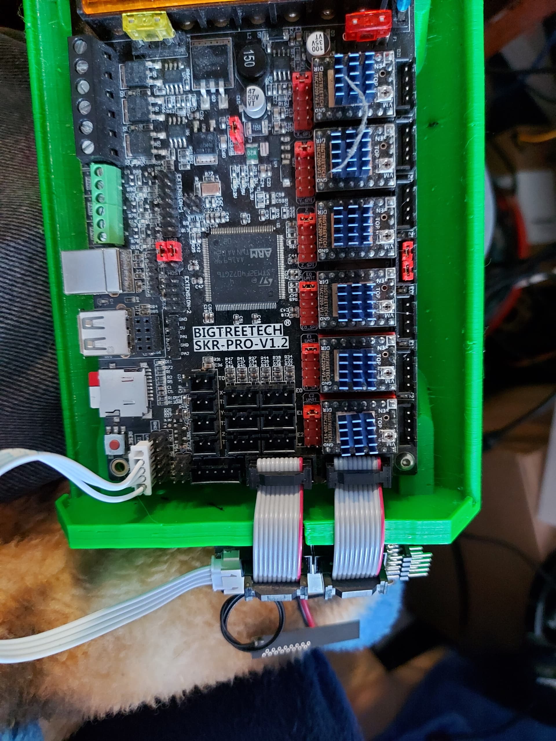
I got RepRap running on my SKR Pro 1.2 although I had to experiment quite some time.

Must confess I will probably stick with RRF if I can get it all running. There seems to be some very nice features I didn´t have on Marlin (like not being able to move outside my bed area, needing to home first before I can move, auto increase Z height on moves… some basic stuff that I had some issues with in the past that will make life easier).

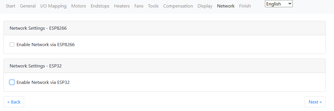
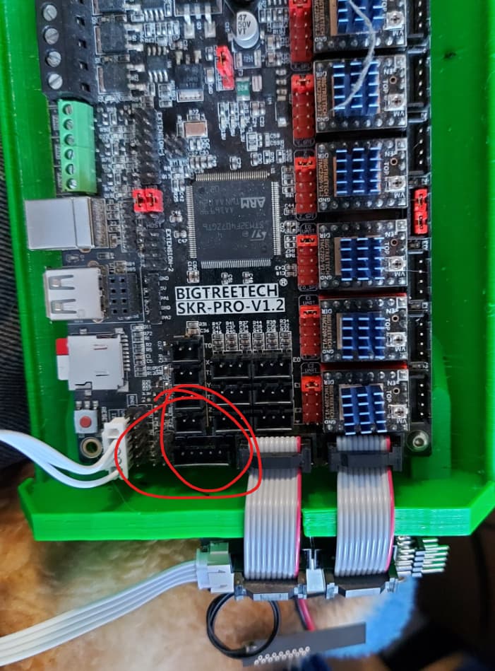
I didn´t manage to get the display working using EXP1 & 2. But that wont be a big deal as in the end those will be used for the wifi adapter. So I updated “board.txt” to the following config, to remove those settings:

// Board Hardware configuration file for SKR Pro
// generated by RepRapFirmware Configuration Tool (LPC Version) v3.4.0-LPC-STM32+6 
// on Fri Apr 07 2023 12:00:45 GMT+0200 (Midden-Europese zomertijd)

//Note: Each line should be less than 120 characters.
//    : Unwanted options can be commented out or set to NoPin. Lines commented out will get default values
//    : for pins the default is NoPin.
//    : Values for Arrays need to be contained within { and }
//    : Comments can be defined with // or # (comments are not supported inside arrays)
//    : Each config entry must be all on a single line.

board = biquskrpro_1.1; 

//LED blinks to indicate Platform is spinning or other diagnostic 
//Comment out or set to NoPin if not wanted.
leds.diagnostic = A.7; 


heat.tempSensePins = {}; //Max of 3 entries
//heat.spiTempSensorCSPins = { }; //Max of 2 entries


//TMC Smart Drivers
stepper.numSmartDrivers = 5;

//Connecting a screen to a SKR Pro v1.1 and v1.2
//https://teamgloomy.github.io/skr_pro_screen.html
serial.aux.rxTxPins = { PA_10, PA_9 }

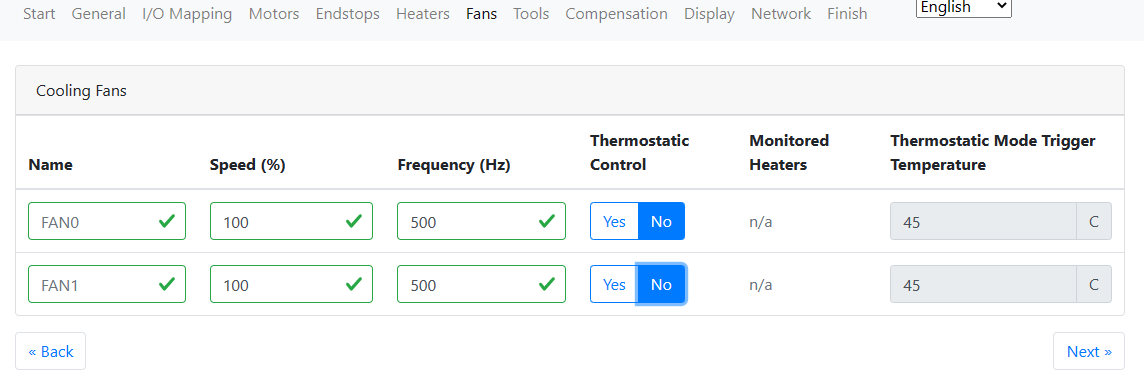
Next, it took me some trails before I got the display running. I know it was working since my fans ran so figured it would be some issue with baudrate. As I am using the latest V1 TFT firmware I had to grab those settings (250K)

M575 P1 S2 B250000

I previously used the steppers on my LR2. During some firmware upgrade 2 of the steppers had been reverted in coding. Obviously that came in to play as they now wanted to go each into another direction :upside_down_face:
So I had to modify the running direction and that seemed quite easy in RRF! Love it :slight_smile:

; Drives
M569 P0 S1                                      ; physical drive 0 goes forwards using default driver timings
M569 P1 S0                                      ; physical drive 1 goes backwards using TMC2209 driver timings
M569 P2 S1                                      ; physical drive 2 goes forwards using default driver timings
M569 P3 S1                                      ; physical drive 3 goes forwards using default driver timings
M569 P4 S0                                      ; physical drive 4 goes backwards using TMC2209 driver timings

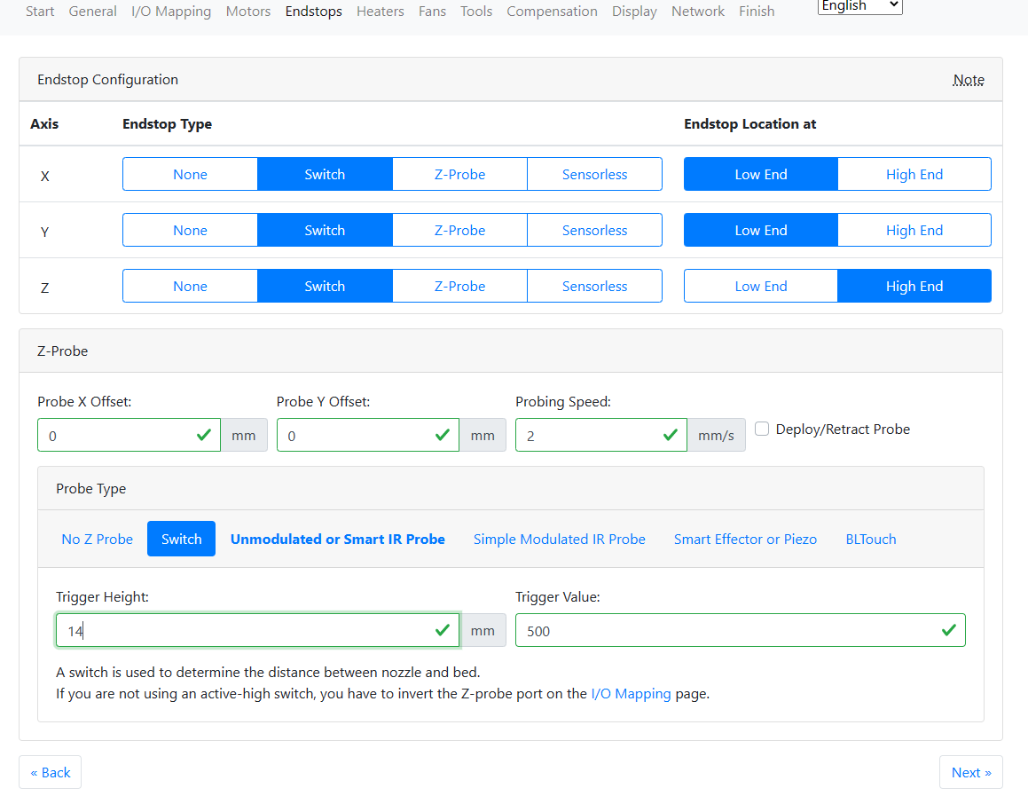
This did the trick for me, to activate the X endstop.
However for the Y´s I had to change your settings as the combination did not work. (still have to check that each endstop correspondents to the correct motor)

; Endstops
M574 Y1 S1 P"^ystop"                      		; configure switch-type (e.g. microswitch) endstop for low end on Y via pin ystop
M574 E0 S1 P"^e0stop"

Unfortunately I seem unable to figure out the settings for the Z endstops.
I now have the below code. Re-reading your previous comment I consider adding an exclamation to see if that helps.

M574 Z1 S1 P"^zstop"                     		; configure switch-type (e.g. microswitch) endstop for high end on Z1 via pin zstop
M574 E1 S1 P"^e1stop"

A short homing session (without Z) worked fine on X & Y. So I am confident to get all things working just fine.

Important to note is that the SD card needs to be insert all the time to work. I hope I will manage to get USB stick to work too as I am not a fan of using the SD card (during my quick tests I already corrupted one :s ).

I will also need to reconfigure the TFT. The error “no printer connected” remains on the screen although it all works. In the BTT github I´ve seen a separate config file for RRF so that will likely have some fixes for it.

I have the TeamGloomy wifi adapter to run the DWC on my SKR Pro.


It uses the EXP1 and EXP2 cables and a serial connection. It doesnt use the same serial connection as the TFT35 though.

I think the TFT needs to be meddled with to act more like the PanelDue controller and I’m working on that. I haven’t managed to enable the other serial port for the TFT or got it to talk, but I believe that I can make it work.

Duet boards are supposed to use a 12864 controller, so there may be a way to make the EXP1/EXP2 ports.work, but I think it would disable the wifi module.

It may be possible to make the DWC work on an ESP01S module in the Wifi port too, or use that serial port.

This should be much simpler for a CNC than it will be for me, since I want to get a printer working on it, so I will need to deal with heaters and thermistors as well.

cool! Might order the module too, however leadtime would be around may or june :melting_face: But for me wifi is not that important for now.

I am using the “TFT35 E3 V3” and it drops in the regular serial TFT port, just had to play with the serial port number & baudrate to get it working. So I would advice to try that one first.

true! setting it up for printing will be harder. For CNC I just use M453 to disable all this and use CNC commands.

as far as I understood the wiki the serial port on your wifi module is optional, in case you are willing to update it over the air.

In the meanwhile I managed to get the Z endstops to work too (using the “!”) however when the stops trigger one side looses power and drops down. I believe my homing speed is to fast and causes some overload.

Maybe @Ryan could give some insights on the different choosen speeds for the V1 Marlin build? It might be a nice addition to the other V1 firmware builds too I believe.

Anyways, in case one is interested, this is my full working config (but as mentioned speeds need to be corrected).

; Configuration file for SKR Pro (firmware version 3)
; executed by the firmware on start-up
;
; generated by RepRapFirmware Configuration Tool v3.4.0-LPC-STM32+6 on Fri Apr 07 2023 12:00:45 GMT+0200 (Midden-Europese zomertijd)

; General preferences
G90                                             ; send absolute coordinates...
M83                                             ; ...but relative extruder moves
M550 P"CNC_LR3"                                 ; set printer name

; Network
M552 S0                                         ; disable network

; Drives
M569 P0 S1                                      ; physical drive 0 goes forwards using default driver timings
M569 P1 S0                                      ; physical drive 1 goes backwards using TMC2209 driver timings
M569 P2 S1                                      ; physical drive 2 goes forwards using default driver timings
M569 P3 S1                                      ; physical drive 3 goes forwards using default driver timings
M569 P4 S0                                      ; physical drive 4 goes backwards using TMC2209 driver timings
M584 X0 Y1:3 Z2:4                               ; set drive mapping // MODIFIED X on drive 0, Y on 1 and 3, Z on 2 and 4
M350 X16 Y16 Z16 E16:16 I1                      ; configure microstepping with interpolation
M92 X80.00 Y80.00 Z400.00 E80.00:80.00          ; set steps per mm
M566 X900.00 Y900.00 Z60.00 E900.00:900.00      ; set maximum instantaneous speed changes (mm/min)
M203 X3000.00 Y3000.00 Z900.00 E3000.00:3000.00 ; set maximum speeds (mm/min)
M201 X180.00 Y180.00 Z80.00 E180.00:180.00      ; set accelerations (mm/s^2)
M906 X900 Y900 Z900 E900:900 I30                ; set motor currents (mA) and motor idle factor in per cent
M84 S60                                         ; Set idle timeout

; Axis Limits
M208 X0 Y0 Z0 S1                                ; set axis minima
M208 X646 Y2092 Z125 S0                         ; set axis maxima

; Endstops
M574 X1 S1 P"^xstop"                            ; configure switch-type (e.g. microswitch) endstop for low end on X1 via pin xstop
M574 Y1 S1 P"^ystop"                      		; configure switch-type (e.g. microswitch) endstop for low end on Y via pin ystop
M574 Z1 S1 P"!^zstop"                     		; configure switch-type (e.g. microswitch) endstop for high end on Z1 via pin zstop
M574 E0 S1 P"^e0stop"							; configure switch-type (e.g. microswitch) endstop for low end on Y2 via pin xstop
M574 E1 S1 P"!^e1stop"							; configure switch-type (e.g. microswitch) endstop for low end on Z2 via pin xstop

; Z-Probe
M558 P5 C"!^probe" H5 F120 T6000                 ; set Z probe type to switch and the dive height + speeds
M558 H30                                        ; *** Remove this line after delta calibration has been done and new delta parameters have been saved
G31 P500 X0 Y0 Z14                              ; set Z probe trigger value, offset and trigger height
M557 X100:600 Y150:2000 S100                    ; define mesh grid

; Heaters
M140 H-1                                        ; disable heated bed (overrides default heater mapping)

; Fans
M950 F0 C"fan0" Q500                            ; create fan 0 on pin fan0 and set its frequency
M106 P0 S1 H-1                                  ; set fan 0 value. Thermostatic control is turned off
M950 F1 C"fan2" Q500                            ; create fan 1 on pin fan2 and set its frequency
M106 P1 S1 H-1                                  ; set fan 1 value. Thermostatic control is turned off

; Tools

; Custom settings
M453											; set to CNC mode
												; https://docs.duet3d.com/User_manual/Reference/Gcodes#m453-select-cnc-device-mode

; TFT
M575 P1 S2 B250000								; Set TFT serial port & baudrate to TFT settings
												; https://teamgloomy.github.io/skr_pro_screen.html

edit; after some testing my fair came true, only 1 endstop triggers on Y, and on Z I seem to unable to get it working for now.
edit 2; managed to get dual endstops to work on Y, but Z refuses to trigger…
edit 3; managed to get Z stops working (needed to use e2stop instead of zstop)

For diagnosing end stops, M119 os your friend, though the output for RRF just reports once per axis.and will report triggered if either one of the Y or Z stops.

If you needed the ! For the Z stops, you may have wired then as normally open. I don’t think this is necessarily bad, but it’s nonstandard. For a 2 wire switch, all of the end stops and touch plate should have the ^ on the pin declaration as well.

This syntax looks wrong. I would expect more like this:

M574 S1 X P"^xstop"
M574 S1 Y P"^ystop+^e0stop"
M574 S1 Z P"^!zstop+!^e1stop"

The order of the pins joined by the + is the same order as the motor drives in the M584 commands earlier. This is how the homing knows to stop both motors at the appropriate places.

1 Like

Yeah, I followed the LR3 guide to the letter, so wired them as shown there :slight_smile:
I´ve noticed that they way the RRF is been set, at source, is different than how V1_Marlin has been set. So pointers to the endstops are odd.

By now I have all motors running in correct direction, and all sensors work, linked to the correct stepper motor. I also have the probe working just fine :partying_face: :partying_face:

This is how I have the config set up:

; General preferences
G90                                             ; send absolute coordinates...
M83                                             ; ...but relative extruder moves
M550 P"CNC_LR3"                                 ; set printer name

; Network
M552 S0                                         ; disable network

; Drives
M569 P0 S1                                      ; physical drive 0 goes forwards using default driver timings
M569 P1 S0                                      ; physical drive 1 goes backwards using TMC2209 driver timings
M569 P2 S1                                      ; physical drive 2 goes forwards using default driver timings
M569 P3 S1                                      ; physical drive 3 goes forwards using default driver timings
M569 P4 S0                                      ; physical drive 4 goes backwards using TMC2209 driver timings
M584 X0 Y1:3 Z2:4                               ; set drive mapping // MODIFIED X on drive 0, Y on 1 and 3, Z on 2 and 4
M350 X16 Y16 Z16 E16:16 I1                      ; configure microstepping with interpolation
M92 X80.00 Y80.00 Z400.00 E80.00:80.00          ; set steps per mm
M566 X900.00 Y900.00 Z60.00 E900.00:900.00      ; set maximum instantaneous speed changes (mm/min)
M203 X3000.00 Y3000.00 Z900.00 E3000.00:3000.00 ; set maximum speeds (mm/min)
M201 X180.00 Y180.00 Z80.00 E180.00:180.00      ; set accelerations (mm/s^2)
M906 X900 Y900 Z900 E900:900 I30                ; set motor currents (mA) and motor idle factor in per cent
M84 S60                                         ; Set idle timeout

; Axis Limits
M208 X0 Y0 Z0 S1                                ; set axis minima
M208 X646 Y2092 Z129 S0                         ; set axis maxima

; Endstops
M574 X1 S1 P"^xstop"                            ; configure switch-type (e.g. microswitch) endstop for low end on X via pin xstop
M574 Y1 S1 P"^ystop+^e1stop"                    ; configure switch-type (e.g. microswitch) endstop for low end on Y via pin ystop & e1stop
;M574 Z2 S1 P"^zstop+^e0stop"                    ; configure switch-type (e.g. microswitch) endstop for high end on Z via pin zstop    
M574 Z2 S1 P"^e2stop+^e0stop" 					; configure switch-type (e.g. microswitch) endstop for high end on Z via pin e2stop & e0stop

; Z-Probe
M558 P5 C"!^zstop" H5 F120 T600                 ; set Z probe type to switch and the dive height + speeds
M558 H30                                        ; *** Remove this line after delta calibration has been done and new delta parameters have been saved
G31 P500 X0 Y0 Z14                              ; set Z probe trigger value, offset and trigger height
M557 X100:600 Y150:2000 S100                    ; define mesh grid

; Heaters
M140 H-1                                        ; disable heated bed (overrides default heater mapping)

; Fans
M950 F0 C"fan0" Q500                            ; create fan 0 on pin fan0 and set its frequency
M106 P0 S1 H-1                                  ; set fan 0 value. Thermostatic control is turned off
M950 F1 C"fan2" Q500                            ; create fan 1 on pin fan2 and set its frequency
M106 P1 S1 H-1                                  ; set fan 1 value. Thermostatic control is turned off

; Tools

; Custom settings
M453											; set to CNC mode
												; https://docs.duet3d.com/User_manual/Reference/Gcodes#m453-select-cnc-device-mode

; TFT
M575 P1 S2 B250000								; Set TFT serial port & baudrate to TFT settings
												; https://teamgloomy.github.io/skr_pro_screen.html

For the homing of Z axis I had to change the macro too;

; tweaked config to avoid stall and doing a second slower homing session
G91              	; relative positioning
G1 H1 Z300 F300   	; move Z toward Z max until the endstop is triggered (fast)
G1 Z-10         	; backoff a bit for second check
G1 H1 Z25 F120 		; move Z toward Z max until the endstop is triggered (slow)
G92 Z129         	; set Z position to axis maximum (you may want to adjust this)

Otherwise it didn´t back off and rehome a second time. Probably I can speed up the first move to a faster setting, but for now that´s ok.

So next is re-doing the TFT config so it fully supports RRF, and then figuring out the speeds for operations as I am still not confident if this is ok.

that homez.g looks good.

With Marlin, you make adjustments to the heights of the end stops with M666. That doesn’t work with RRF, but you can reassign the motors on the fly, so my homez.g looks like this:

G91                                             ; relative positioning
;G1 H2 Z5 F6000                                  ; lift Z relative to current position
G1 H1 Z200 F1800                                ; move quickly to Z axis endstop and stop there (first pass)
G1 H2 Z-5 F6000                                 ; go back a few mm
G1 H1 Z20 F360                                  ; move slowly to X axis endstop once more (second pass)
M584 X0 Y1:3 Z2 U4                              ; set drive mapping: X on drive 0, Y on 1 and 3, Z on 2 and 4
G0 H2 Z-1.6530                                  ; Offset for Z1 motor
M584 X0 Y1:3 Z2:4                               ; set drive mapping: X on drive 0, Y on 1 and 3, Z on 2 and 4

;G1 H2 Z-5 F6000    ; lower Z again
G90                ; absolute positioning

So after a very standard home Z, much like yours, but… faster :wink: I use M584 to reassign the axes, so that Z is only drive 2 and assign axis U to drive 4. After that, I can adjust Z down by 1.653mm and only drive 2 moves. (Or I could adjust U down if my stops were tilted the other way) then I reassign the drives back the way they were so that both move in lockstep.

I do the same thing for homing Y (Except there, just to keep things clear for me, I use the temporary axis V) I then made the same adjustments to homeall.g With that, I have everything square after homing.

1 Like

yeah, I set it to a real slow speed to avoid one off the steppers to drop (using 12V). Might wanne change speeds one day.

good suggestions on the homing part!

But I am stuck with the screen. It runs “fine” on the serial port but I do get the error “no printer connected”. Funny thing is, I can home all axes and move them afterwards.
But I can not start any job because it doesnt see a printer :upside_down_face:

Weird bug. Tried various serial ports in config + on hardware (SKR side), baudrate from 57K to 250K. It doesn´t matter it keeps on shouting “no printer attached”. I also upgraded the TFT FW, resetted it, changed config,… nothing helps…

I am a bit stuck I am affraid.

I did get this error to on marlin (touch menu) but the error gets away after 5 seconds. On RRF it persists that no printer is attached. I consider trying to use another uart port on the TFT, but that will be the last resort I think