"RatRider" LR4 Build in the UK

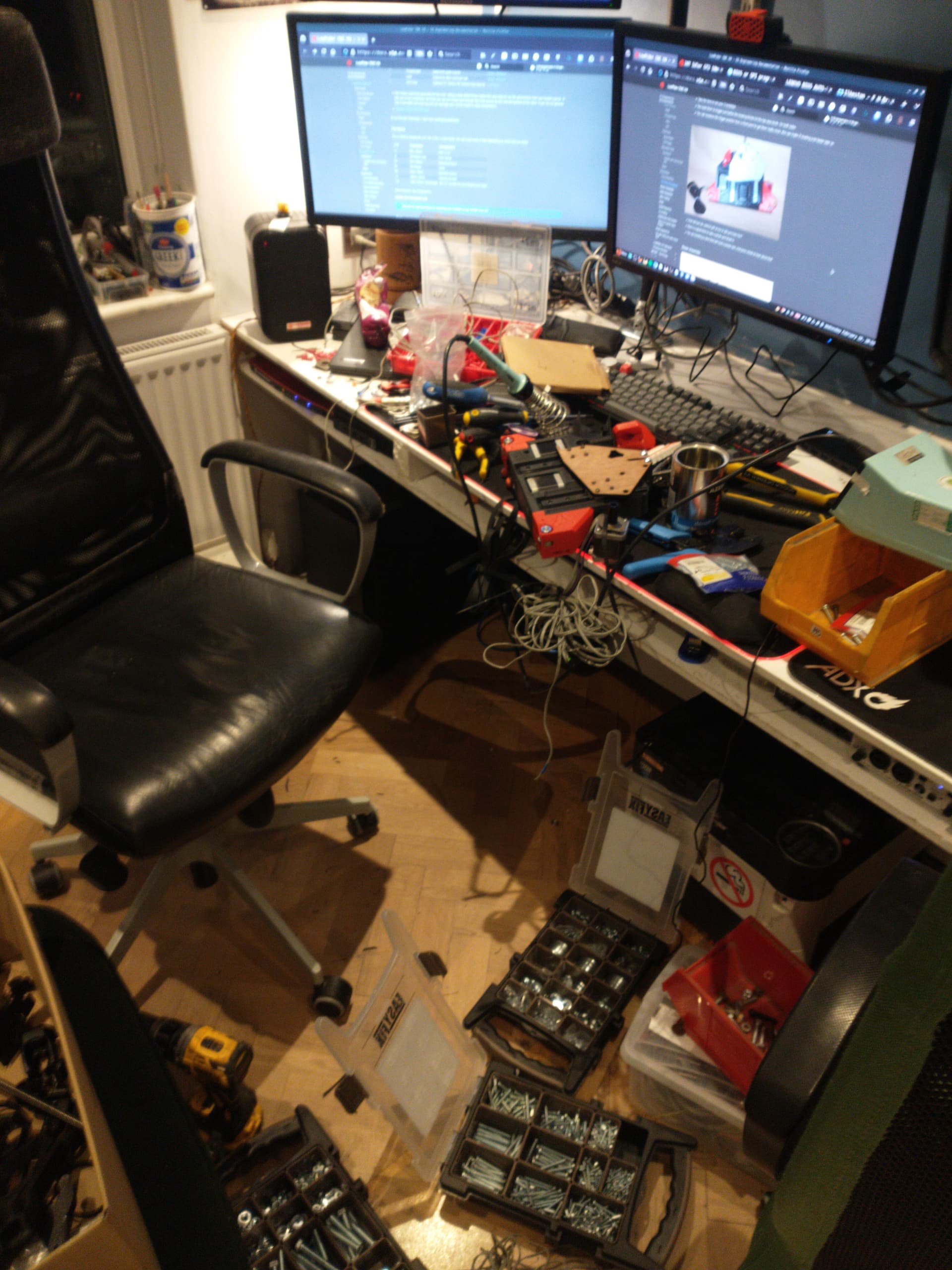
Per LR4 Rails - UK - #6 by FreneticScribbler I’m currently in the process of throwing together a parts bin full sheet LR4, recycling parts from a Chiron printer. Far from the “yellow brick road” approach, and at this point I’d add my voice to all the others saying take this road. Down my path lies faff and madness. I have had fun and enjoyed myself though :smiley:

Lots of little snags I’ve had to solve because of my rat rig approach - not least that the endstops I picked for Y didn’t have long enough levers to reliably trigger. And the paint thing mentioned in the other thread. Real world forehead slap when I realised what I’d done to myself there… !

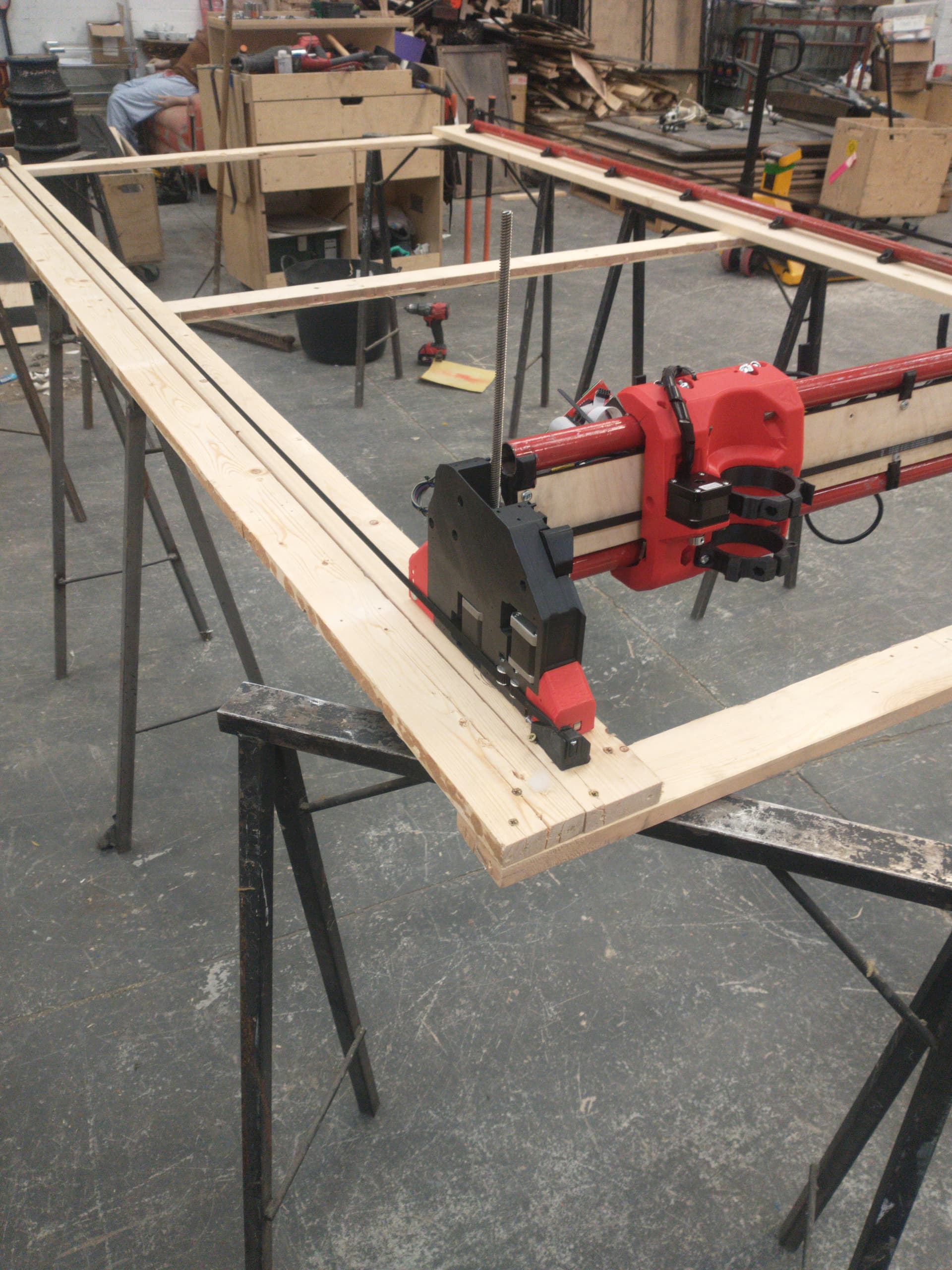
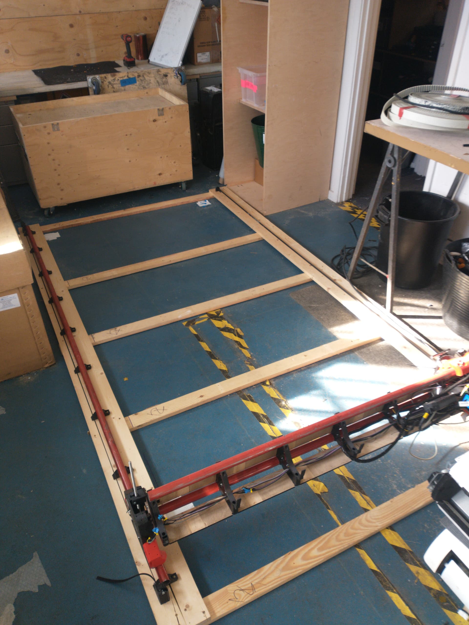
Nevertheless, nearly at the point of a ready to go machine here. For now, I’m running the machine with the Trigorilla board out of the Chiron, which has been… fun. Totally appreciate it’s not a yellow brick road config and so I can’t (and don’t!) expect help but figured I’d post up just in case someone else is doing the same and has hit all the same speedbumps I’m currently encountering. My steppers are moving further in the real world than commanded to by Marlin - I guess this is the Trigorilla board having the wrong microstep setting? My Y axes are also moving different amounts of wrong, to boot, but I’m pretty sure this is because I seem to have mismatched the motors (not all the motors from the donor machine are created equal) so I’m going to swap one out tomorrow and see if that solves that, at least.

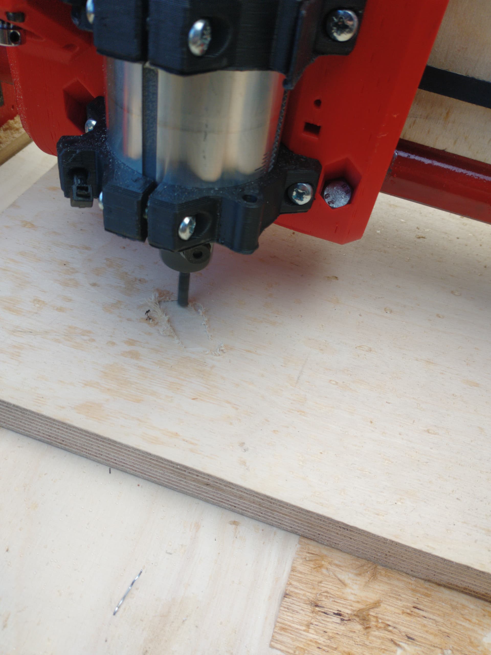
A Jackpot board is in my shopping basket! (but I’d still like to get the machine making chips in the intervening time)

ETA: Also possible I’m using pulleys with the wrong number of teeth, I’d best check that too…

4 Likes

Some amount of going cross eyed counting tiny teeth later… One Y axis motor with a 16t, one with a 20t. 20t on the X axis as well. Doh! :person_facepalming: More 16ts on order as apparently the one I used was the only one I had kicking about :thinking:

Swapped the Y axis motors to be a matching pair whilst I was at it, at least.

Doesn’t explain why the side with the proper 16t was also moving further than expected, though. As far as I can tell the trigorilla board is fixed at 1/16th microstepping - is this correct? Swear I remember reading what the microstep settings should be somewhere in the docs, but now can’t find it for the life of me - can’t seem to find configuration related to this in the firmware, either. Probably will right after posting it - sometimes I gotta reverse psychology my luck… E: ding Searched docs, didn’t search the forum hard enough. This thread has me on the right track, for the reference of any future ratrunners (again. Don’t. just get the kit :p). Already had to customise the firmware slightly because my endstops only have NO pins (yes, sad, switching to NC is high on the priority list)

That Jackpot board looking sweeter by the second…

2 Likes

Swapped to correct pulleys and adjusted steps per mm to match the fixed 1/16th micro stepping on my board.

All axes moving the right distance and homing. Reeeeasonably square, needs a bit more fiddling, but higher priority is working out why my Z0 axis keeps skipping steps driving upward. I don’t think the rails are binding, they moved pretty well at assembly. Lubed them and the screw to no difference. Wiring fault maybe - my extensions are soldered so could well be a bad joint. Or my temp YZ plates - lasered from 6mm ply (under the possibly wrong theory they’d be better than printed ones!) are rubbish :thinking: Will cut ally ones as a priority once I trust the machine to hold a power tool…

Also possible motor current is wildly wrong. I did make an attempt at setting them all correctly but I need to idiot check what drivers are feeding what pins as on this board there are 6 sockets and 5 drivers… So I think I could be driving two motors off one driver unintentionally

1 Like

Hiya @FreneticScribbler Welcome to the forum. What steppers are you using and what did you set your amps to - looks like you are starting with your own config? I find I have to set mine a wee bit higher on the stepperonline motor’s I’m using, both on the fluidnc board and marlin boards, I think they need a little more current to get the required torque - do yours get at all warm? Best to check all the mechanical stuff too though. The jackpot board is a great choice, fluidnc is a much nicer experience than marlin imo.

1 Like

Ahoy! I’m using steppers salvaged from the same Chiron printer I got the trigorilla out of. They were not all the same - the Z axis ones are 60mm not 48mm which I assume/hope means higher torque… rather unhelpfully there’s no information printed on them. Neither they nor the Y axis motors get warm. X gets a bit toasty, I think I need to swap that for something with a bit more grunt.

Current is currently set at 1A for all the motors. Probably wants to be higher for the Z axis.

And yes - the second I get the spare cash in my projects fund I’m swapping to a jackpot (with nicer stepper drivers while I’m at it, the stock Chiron ones are junk…) and relegating the Trigorilla to something less important. Like a ZenXY. Some zen in my life sounds lovely right now :laughing:

Ahoy matey, you’re along way from the quayside, in Nottingham! 1A should do it. If those steppers need more than 1a to deliver then I think you’ll get other problems. The one’s I have are rated to 2a (i run them at 1) I think but that isn’t a good thing, you want them to deliver the power with less juice. It’s all a bit anecdotal and my understanding is vague (possibly/probably just wrong), but I think the one’s Ryan sells, can’t remember the brand, are lower power needed, so they can be run with less amps and run without overheating the drivers. Whereas If I to run my steppers until they get hot then the drivers will overheat. If you’re ordering the jackpot, might be worth getting the steppers from Ryan too, I wish I had just for ease of troubleshooting etc.
Hope you get that zen.

1 Like

Yes, drivers overheating is a real possiblity - haven’t got a board box yet, much less a fan…

I was going to get the board from Elecrow to save the international shipping - would like to get the machine working with the steppers I have, though appreciate it would be a less of a headache not to.

Need to double check I’ve actually set 1A. I might have misunderstood the stuff I read about the process.

Just noticed the 5 to 8mm couplers in the shop are flex couplers. I’m currently using rigid ones since that’s what I had on hand. Might be exacerbating/causing my Z issues?

Very much starting to wish I’d just ordered the full kit shipping cost and recycling iniative be damned :confused:

1 Like

Reference list of my snags so far, figured it might be a useful thing to others. Also definetely going to be useful to me when I get a chance to get back to playing with the machine in a few days.

I’ll try and keep this updated as the build progresses, but hopefully there’s not much more to add…

Fail Cause Fix
Core moving rough (Badly) painted rails DO NOT do that. Sandpaper & swearing.
Endstops not triggering Cheap endstops NO only, not NC D: Temp: Invert in Firmware. Soon :tm: Swap to NC endstops
All axes moving too far Trigorilla board hardcoded to 1/16th Microstepping, not 1/32 Temp: Halve steps per mm in firmware. Soon :tm: Jackpot!
Y axes moving different distances Mismatched Y motors, 20T pulley on one Y motor Don’t do that, ya goof!
Y endstops not triggering Levers weren’t long enough Temp: Extend levers Soon :tm:
X endstop not triggering Little lever broken off after assembly somehow. Oops. Temp: Tiny stop block added for it to hit against. Soon :tm: Swap out for new
Y badly out of square User awful at making things square Do better. Moved Y1 belt relative to Y0 which took the error down from 4cm to 1cm. Still the wrong order of magnitude but I’ll get there.
Z0 missing steps when trying to climb TBD

Troubleshooting I’m going to try for Z0:

  • Retest wiring for continuity, including a ‘jiggle test’, to try and rule out an intermittent wiring fault
  • Swap to flex couplers for the rod when they arrive (Aliexpress, so may be some time)
  • Swap out rod, may be bent/damaged
  • Check tolerances on printed parts, they might not be fitting together as they should, I may not have done enough post processing.
  • Ditto for linear rails running true and free but it felt pretty damn good at assembly time.

I also need double check stepper current and that the Z endstops are stopping the right motors. I’m pretty sure they are, but I can’t think that I ever actually checked.

Then I can finish off squaring Y, level the beam and it should be time to make some chips…

In two minds about sharing photos, because what I have right now is sloppy enough that I kind of feel it’s insulting to Ryan’s glorious design work :sweat_smile: Hoping that my being open with the pains of a path far from the yellow brick paving encourages others to take that route well travelled, at least. And I bet that when I add up everything I’ve spent “here and there” it won’t have worked out that much cheaper than a kit, and will definetely have eaten more time.

2 Likes

Please share the photos. The “yellow brick road” issues are more associated with giving advice to people that ask. Ryan loves seeing his designs in any form manifest somewhere and combine with the mad scientists around the world. I do too.

2 Likes

Mad scientist is certainly what I am… Heavy on the mad and light on the scientist :laughing:

I never take many pictures anyway but here’s an action shot from a predictably chaotic assembly process… Bloody awesome documentation, for the record.

I started off just using up odds and ends of PLA, but black and red actually turned out quite a cool colour scheme :smiley: Wish I’d done some engraving on the strut plates…

Then I didn’t take any more until it was time to build a “table” which is really just an open frame… I’ve built a minimum viable product (possibly even a bit less than that…) because I need to keep it light enough to be able to get on my roof rack. I should really have built the thing small enough to fit in the van, and in the shed, but for some reason I was set on the idea of being able to break down a 8x4… Might end up shortening the Y axis after all this, once I get some cuts under my belt an a better idea of the working area I need.

Completely unsurprisingly, having it on trestles it bounced around far too much with the flimsy frame but on the floor it seems viable.

I’ll build something a bit more serious once I have somewhere to put it at home - can’t keep it at work long term sadly. Can just about see my temporary wiring nest in that one. Again, something to be revisited when I upgrade to a Jackpot…

Been torn away from it this weekend to pretend to be a groundworker, but raring to get back to it…

5 Likes

I have wondered about that. Printing too. If the workpiece is rigidly mounted to the frame and the LR is rigid to the frame, then the wobble in the kegs just means the change in directions has a place to go. Sort of like a crumple zone in a modern car.

This looks great! I love a little mad. Btw, there is a desk in the first room. :stuck_out_tongue:

Besides that: Your steppers look pretty small, your X stepper might have problems when you go faster later on. Just a heads up. :slight_smile:

1 Like

No matter how big the desk, it’s never enough…

X stepper probably does want to be be beefier, yes. Not sure exactly how beefy my Y ones are…salvaged, and there’s zero information on the casing. Fortunately Ryan has made swapping them out super easy :grin: The design work has made me grin at several points…

2 Likes

Well, I did begin to swear building the third beta… :sweat_smile:

1 Like

Swapping to flex couplers and a bit of smoothening of the Z nut parts seems to have aaaalmost completely cured my Z axis problem. It still loses a step every so often, but not every single time as before. Pretty sure it’s mechanical, not electrical. More data required.

I also redid stepper current settings, because it turns out I’d set it totally wrong before :sweat_smile:

Y square is pretty close now, within a mm or two. Lots of error coming from the pen moving around and my (in)ability to measure. So I decided to stop agonising over calibration and run some gcode. Drew a test crown on a random bit of ply that turned out to be a lot less flat than I thought. My poor pen :laughing:

Going to have to hold off giving it a power tool a little while longer if I don’t want my neighbours to yell at me. But soon

Thanks for all the help so far everyone :smiley:

2 Likes

Nyooooom. Was bored to waiting for my 1/8" single flute upcut to arrive, tried some test cuts with the regular 1/4" router bit I bought with the router. It made the most ungodly noises, but gave me some usable results. Engraved the V1 logo using the settings from Milling Basics - felt like the only appropriate test. Rather unsurprisingly, the finish wasn’t great :laughing:

At that point I was still on the back deck (which is apparently tradition in these parts?). But I’m in the UK, not America, so my back deck is just that. No fancy roof. And again, I’m in the UK… so it started hailing out of a clear sky…! Fortunately, I’m much practised in covering electronics from sudden unscheduled water (small festival gigs that don’t spring for a covered stage…) and no harm was done.

Cue next day turfing everything out of my shed. And then remembering the shed is 8ft by 8ft. Once again, making the machine smaller would be the sane option. So, obviously, I built the shed a back deck of it’s own. US style, with a roof. :laughing:

So now the LR frame fits mostly in the shed, with the far 1ft of Y (which I may not ever use anyway after all this :rofl: ) sticking out into the shonky new “porch”. It’s not ideal - I’ll be bringing the gantry indoors proper when not in use (those quick release belt mounts are a work of bloody genius) and reckon I’ll be making the board box from a weatherproof project box! But it’ll keep the hail off, which is a damn good start!


Still with the 1/4" standard router bit… Worked pretty good for the first cut. Then started throwing the gantry around on me. Done quite a bit of playing with feeds and speeds, all good learning and I’ve managed not to break anything :smiley: (I’ve since made the dodgy looking router wiring marginally less dodgy. Going to redo it properly and put a relay in when I do the proper box for the electronics. Cobbler’s children…plus having too much fun atm to want to take it apart!) Well, pretty sure I’ve killed the router bit but hey.

Also think I’ve cracked my Z uplift problem - my bootstrap 6mm ply end plates are, unsurprisingly, flexing inwards quite a lot when the gantry is all up, causing the printed part to pull away on the other side and the screw to be all kinds of wonky. Explains why it gets notably worse the higher up it is, and why swapping to flexible couplers helped some but didn’t cure it. Going to cut some Alu plates on the local makerspace’s Superbox I think, rather than trying to feed metal into this as is. But the machine is still totally usable in the meantime, it only starts to skip in the very upper region of Z travel.

Can’t remember if I said it already, going to say it (again?) anyway. This is the coolest godsdamn thing I ever built. Giant smile on my face the whole time I had it running, to rival/beat the first time I watched a 3d printer all those years ago!

Proper 1/8" upcut is here now, so looking forward to getting that dialled in tomorrow. Will try and remember to take some pictures of the setup (and of the Z at full height to illustrate my theory) in between getting chips all over everything :smiley:

5 Likes