My Ramps 1.6 & Arduino Mega Combo is not working anmore.
If I power it via the Ramps’ input (12V), die Arduino’s LED is on but it does not boot and there’s nothing shown on the display but the display lights up.
If I power the bundle using the USB on the Arduino, the Arduino boots and the display works.
I did some measurements and I only get 3V on the display and also on the VCC-Pin.
I did some online research and apparently the Voltage regulator in those cheap Chinese RAMPs Boards burn easily and it is a common issue.
Some people solved this problem by feeding 5V through a buck converter, which I have lying around.
I just don’t really know where to feed the voltage to. Can I just use the VCC-Pin on the J5 connector?
I know, the board is old and maybe I should just upgrade but is has been working well and I would have to print new enclosures and stuff…
So the voltage regulator on the Arduino went bad. Just dealt with this on mine. (Replaced Arduino)
Mine was because I moved the machine manually very fast the LCD went very bright and then nothing!
The ramps does not have a stop for the voltage from backfeed from the steppers.
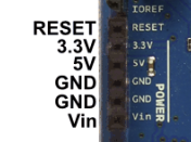
It is highly likely that it is the voltage regulator on the Mega board that is dead. Your buck converter should feed power to the 5V pin on the Mega board:
The Vin pin on the Mega board will take voltage in the range of 7V to 12V and uses a voltage regulator on the Maga board to convert the input voltage to 5V. With the regulator dead, you can feed the 5V pin directly. That is why the (5V) USB connection works.
Thanks for this perfect answer! I think I am going to do it like that.
Just one more question:
When feeding 5V to that Pin on the Mega, can I still connect it to a pc using USB or will that do damage to the PC?
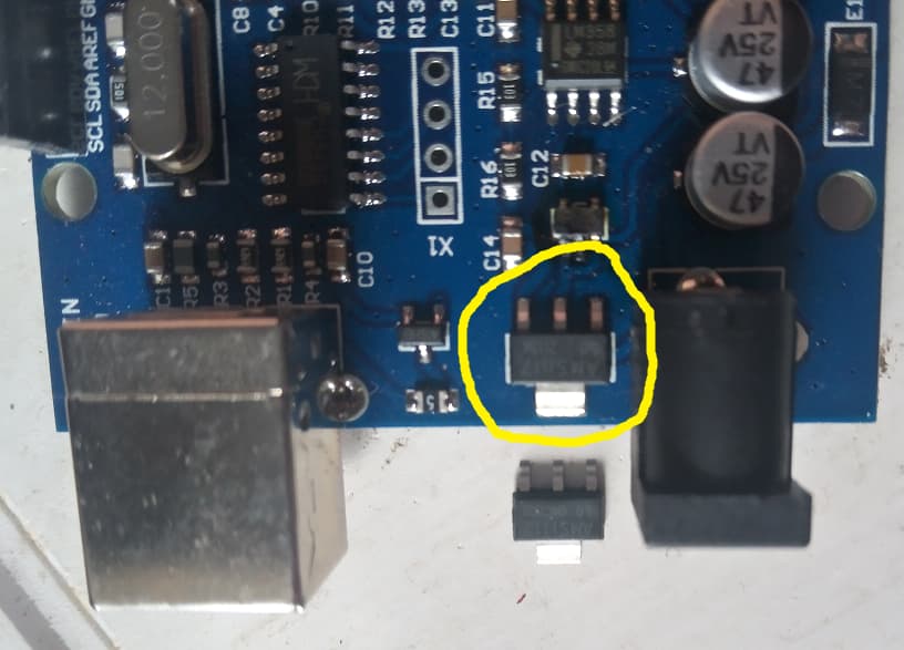
Just replace the voltage regulator. They costs a few cents. see the picture. a new regulator is shown beside the board. It is a LM1117 v5 (make sure you buy a 5V one)
When feeding 5V to that Pin on the Mega, can I still connect it to a pc using USB or will that do damage to the PC?
That’s a good question, and I don’t have a firm answer. My takeaway from some net searches is that it has worked fine for some people, but it is not recommended. One quote:
…you do not want to put a 5V supply on the 5V pin AND be connected to USB at the same time. This will cause the node to have a voltage drop and is not good.
Maybe someone on this forum with more electronics experience can give you a firm answer on what is at risk. I think the risk is to the Mega board, not to the PC.
When you supply higher voltage (6.5 or more) to the Vin pin (and the voltage regulator is working), the board switches to using Vin power when the USB is plugged in. For 5V-in, there is no such switching circuit.
You could cut a USB cable in half and then feed the 5V into the arduino that way. Then you would never forget to remove the 5V when connecting to a computer.
Or have a dedicated USB cable for the control board that has the 5V line disabled. The pin/plate could be removed, or an incision could be made in the sheathing and the 5V wire cut. That way a USB sender could be used to send g-code from a computer for CNC work.
Thanks for all the replies, guys.
I guess trhe easiest option is tzo replace the LM117, I ordered some on Aliexpress and once they’re here, I’ll just replace them.
I’d probably have ordered them from Digikey instead. Still cheap, and Id probably have them in a couple of days.
I’ve been burned getting some output transistors before, apparently counterfeit transistors are a thing, which makes me hesitant to buy components from random Chinese vendors. Even reputable suppliers aren’t 100% certain, but the reputable suppliers will at least try to help you out.