I am running the MPCNC on RAMPS1.4 with ESTLCAM.
Anything works fine.
Now I have loaded GRBL onto the RAMPS Board.
On the Serial Monitor of the Arduiono IDE, the GRBL is responding.
I can connect also with the GRBL PC Software and connect to the board.
The movement buttons also get highlighted.
But nothing moves on the X or X axis.
When I start ESTLCAM, and connect it to the board, there is a noise that indicated to me that the system is working. I am missing that after the GRBL is connectiong to the board.
Also I have cleard the EEPROM as stated in the comments.
I have not set any of the $ commands so far, as there are preset values and I want just to see the axis movements, no matter if they are correct or not.
First question is, do I have to configure somewhere in GRBL the ports for the X,Y and Z axis?
You haven’t loaded GRBL onto your RAMPS board because GRBL is for a 328p processor and a RAMPS 1.4 fits onto a MEGA2560. So first check exactly what you have loaded onto your MEGA2560 and look at what pins it is utilising for X and Y step and dir signals in cpu_map.h because according to the RAMPSv1.4 spec sheet -
Xstep =A0
Xdir=A1
Ystep=A6
Ydir=A7
and the GRBLMega5x -
Xstep=D24
Xdir=D30
Ystep=D25
Ydir=D31
I’ll ask the most basic question first, since I’ve made this mistake myself. Do you have the motor power supply connected to the proper side of the RAMPS plug? The 5 amp side powers the motors and extruder mosfets, the 11 amp side only powers the heated bed mosfet. Never mind. If this was working under Marlin it should be working under grbl.
To answer your original question, the stepper pin assignments should already be in place with the grbl firmware defaults. I’ve never needed to change those for my CNC Shield/Uno hardware, so I wouldn’t think you’d need to either.
You do need to be using firmware with the dual axis configuration enabled, but if you’ve grabbed @enducross’s firmware, I expect that should already be set.
$1=255 keeps the motors engaged permanently once they’ve been activated. Are the motors hard to move? If not, try $X to “unlock” the machine - that should engage the motors to hold their current position.
I’m not using dual endstops, so I haven’t had to play with reversing axis travel directions with $3. If you’re using the same wiring setup from Marlin and didn’t have to invert any axes there, you shouldn’t have to either. If you had to make changes in Marlin for things to move the proper direction, you’ll need to set $3 appropriately or risk twisting the machine once things do start to move. You might consider taking off the belts until you’re sure motion directions are correct.
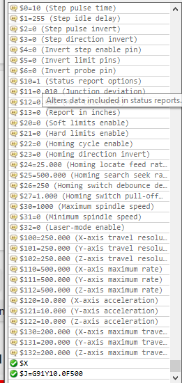
They values for the steps per mm are in your chart - $100, $101, and $102 for X, Y, and Z travel resolution. All are set to 250 steps per mm, which should allow you to see movement. On my MPCNC with GT2 belts for X and Y and a 4-start acme leadscrew on Z, they are set as follows:
$100=100
$101=100
$102=400
I don’t think your settings are so far out that you shouldn’t see motion. If the motors sound like they’re losing steps you might want to lower these settings.
I have intstalled GRBL on the RAMPS Board.
You can see it from the Serial Terminal in the Arduino IDE.
I have LASER GRBL on the PC.
I can connect the PC Software.
I have registered the first GRBL download for the RAMPS board in the Arduino IDE, but once I have downloaded other versions, I have not registered them in the IDE, so I was only downloading the same file again and again. I have noticed this at a very late stage this morning.
Thanx to Mike and Tom, I was able to find my error.
I had to tell the CONFIG.H that I am using the RAMPS Board.
So this line below: #define CPU_MAP_2560_RAMPS_BOARD
Must be used.
Now I have anything working.
The Steppers are fine and I have corrected the steps.
I have also added the command to enable the LASER in GRBL at $32.
That is fine until here.
Now I am stuck in connecting the Laser to the RAMPS Board.
I have learned, the laser Needs a 12Volt Connection to be powered.
I would use the Connection to the heatbed, or a constant Connection direct from the power supply.
In Addition to that I have to connect the TTL PWM connector to the RAMPS board.
I have not found the Right Forum thread how this is done with GRBL and the RAMPS Board.
I understood that the OP is using RAMPS. I was just saying that since the firmware defaults were right when compiling for the Uno, the developers would also set proper default pin mappings when compiling for the 2560 (which the RAMPS runs on top of).
I’m glad to hear @unathome has the motion portion sorted out. I’ve never tried connecting a laser to RAMPS so i dont have any further advice to offer. I know ofhers on the forum have and should be able to guide you through this.
I think I can give you an update now of the story of RAMPS and my Laser, using PWM for power control.
Long story short, I have changed the Electronics to a GRBL Board.
So I exchanged the €22,- RAMPS for a €18,- GRBL.
Until then, the LASER GRBL Software and ESTLCAM are working fine with the MPCNC and the Diode Laser. Because LASER GRBL is using M3 and M5 Commands for turning the Laser On and OFF and the PWM Signal is using the Sxxx command.
For the DREMEL I am using for tests, just ESTLCAM is used as Software.
Both configurations are working fine, so no need for fiddeling around with the RAMPS.
I am sure that somebody can use the RAMPS Board for the LASER GRBL GCode Format. Unfortunately I am not that guy. After I had seached the Internet for two days for an solution and checking various pin redirections on the RAMPS, I was thinking not to invest any more time and did it the easy way by exchanging the electronics.
The RAMPS will now go into an 3D printer, using Marlin.
I am now at the stage that even after 30 years of Software Development work, sometimes your brain capacity is too less to successfully lift the curtain:-)