Hi there,
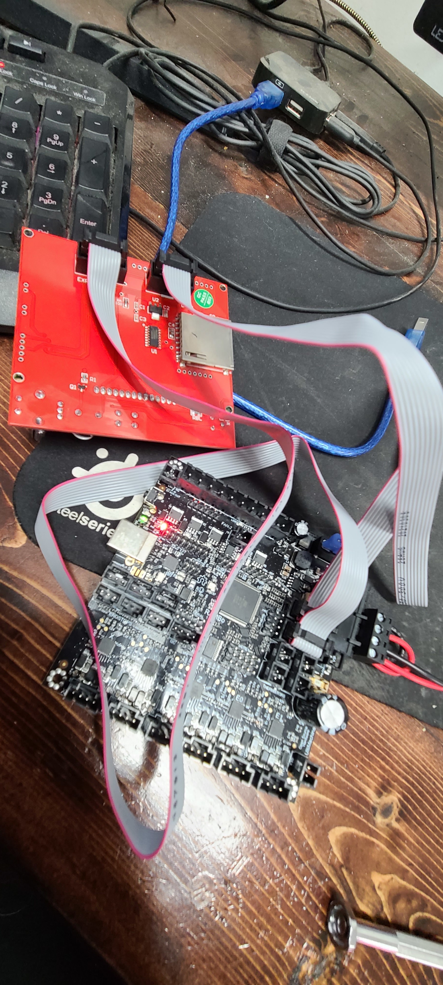
I’m having issues with my RepRapDiscount Full Graphic Smart Controller from the mpcnc store, all I can manage is a blank screen.
I’ve reviewed the thread regarding flipping wires; and I’ve also tried other combinations with no success also swapped cables.
Rambo 1.4a is flashed(platformio first, then xloader with default hex again) with V1CNC_MiniRambo - 2.0.9.2 - 513S, and I can communicate via repetier-host.
Some of these for whatever reason have the keyed connectors the wrong way around, so you have to flip the connector the way that it doesn’t want to let the keyed connector work.
I’ve done it by using a sharp chisel to remove the key from the connector. Other people have had success removing the shield from the board with needle nosed pliers and reversing it (Or leaving it off.)
Ok. Next step, is it enabled in your firmware? V1 firmware does enable the LCD by default, but if you compiled Marlin yourself, you have to have the definition for the 12864 LCD enabled. (Edit: Ok, I see you’ve flashed the V1 513S, which should have that enabled.)
Have you verified the flash with a serial connection to a PC?
The flash went without errors, it said it read it afterwards. Is there another method I should try for verification? I can send m115 and get a reply back ok.
Have you tried flipping one end but not the other? There’s no reason to assume that the ends were put on so that the alignment lugs “match.”
Those connectors (officially IDC or “insulation displacement connectors”) work by poking through the insulation to get to the conductor, and sometimes they don’t poke all the way through. You could try gently squeezing them a little more, like in a clamp or a vice. If you’ve got some male dupont connector wires, or even some stiff wire, you could do a continuity test of the 10 pins in each connector.
Might also be worth inspecting the solder joints for the connections on the controller (since it appears the LCD board already checked out).