Rambo 1.3L TTL Questions (Laser issues)

Im kind of scratching my head here. I think Im trying too much at once.

I have an endurance 10w laser with their laser control module that should respond to TTL. I have hooked up the TTL wires to my Rambo 1.3 running Marlin 2.0, I got it from Ryan. I got version number from the read out :

""
echo:Marlin bugfix-2.0.x
echo: Last Updated: 2018-01-20 | Author: (none, default config)
echo:Compiled: Mar 7 2018
echo: Free Memory: 3785 PlannerBufferBytes: 1296
echo:Hardcoded Default Settings Loaded
echo: G21 ; Units in mm
echo: M149 C ; Units in Celsius
echo:Filament settings: Disabled
echo: M200 D3.00
echo: M200 D0
echo:Steps per unit:
echo: M92 X100.00 Y100.00 Z400.00 E100.00
echo:Maximum feedrates (units/s):
echo: M203 X120.00 Y120.00 Z30.00 E25.00
echo:Maximum Acceleration (units/s2):
echo: M201 X400 Y400 Z400 E8000
echo:Acceleration (units/s2): P<print_accel> R<retract_accel> T<travel_accel>
echo: M204 P400.00 R3000.00 T400.00
echo:Advanced: S<min_feedrate> T<min_travel_feedrate> B<min_segment_time_us> X<max_xy_jerk> Z<max_z_jerk> E<max_e_jerk>
echo: M205 S0.00 T0.00 B20000 X3.00 Y3.00 Z0.20 E5.00
echo:Home offset:
echo: M206 X0.00 Y0.00 Z0.00
echo:Material heatup parameters:
echo: M145 S0 H196 B92 F0
echo: M145 S1 H240 B110 F0
echo:PID settings:
echo: M301 P17.98 I0.98 D83.62
echo:SD init fail
""
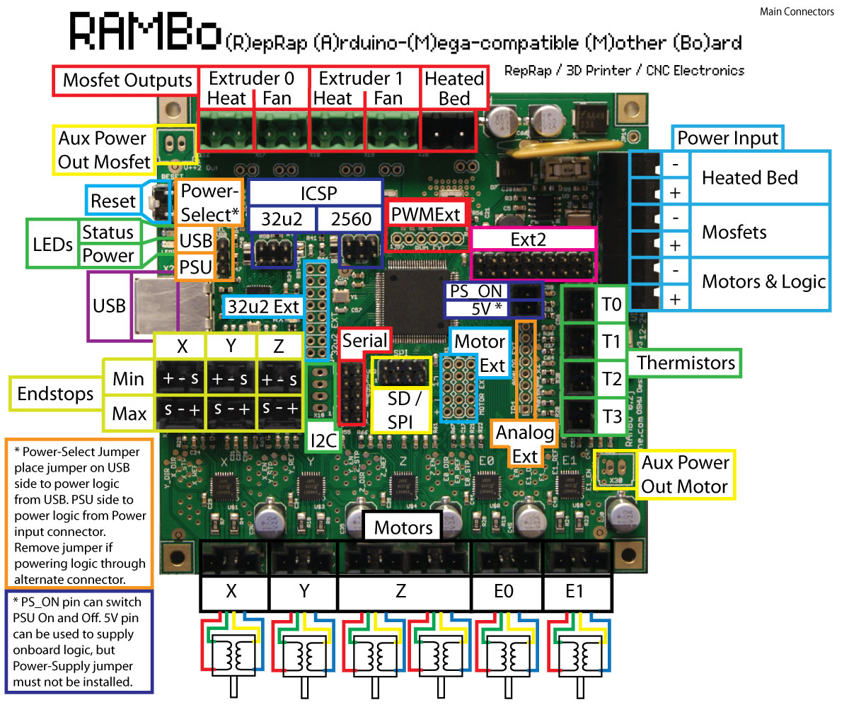
Currently I have TTL hooked up to the MX2 pins 45 and -. However, I am having a hard time testing the TTL output. Hooking up my multi meter isnt giving me a clear reading. Am I supposed to be issuing something other than an M3 XXX command? I have also tried M5. Just to add to the confusion, I tried to look at the 12V output on Fan 0 and im getting the same voltage output at M106 S0 as I am at M106 S255. Kind of feel like im missing something!
Thanks,
Sean

First you need to know if you need 5V or 12V ttl.

From there you will know if you should be using fan codes or laser codes, or if you change the firmware (config_adv.h) you can use laser codes on either.

there is no such thing as 12v TTL :slight_smile:

"Standard TTL circuits operate with a 5-volt power supply. A TTL input signal is defined as “low” when between 0 V and 0.8 V with respect to the ground terminal, and “high” when between 2 V and VCC (5 V),[21][22] "

Probably he can use pin 4 or 5. They are PWM capable and it seems can be found on “PWN extensions” pin set.
It can be controlled directly:
M42 P4 S255
M42 P4 S0


and as I see rambo has 3 separate power inputs. so drivers, heat bed and other mosfets could be supplied by different voltages

I just use it as a simplified explanation, I won’t do it again.

Some lasers use the 12v, some use 5v. Whatever they decide to call it. Heck some use either. We are overloaded with laser questions for this reason. Some are even label backwards -/+.

he said that his laser is Endurance 10W http://endurancelasers.com/endurance-10w-laser/
I hope that Endurance guys when use term TTL on their page mean proper 5V logic.
Yes, guys on aliexpress use ± and that can means anything, they could even make wrong polarity.

Well I know that he references 12v TTL on the page he linked me too: http://endurancelasers.com/getting-started-endurance-lasers/

“All Endurance lasers have TTL output. For models 2.1W, 3.5W, 5.6W, 8W, 8.5W TTL has only 1 wire (control wire) and use the same common ground as for the laser power. It is important that TTL can be controlled with 3.5-12V output (digital). Usually, it connects with PWM output on your mainboard (3D printer / CNC machine or engraving machine).”

I am going to attempt to test the TTL on Pin 45 again, I think im just crazy and losing my mind
 or my multimeter is
 either is possible


Im going to test using the CNCjs commands. Can I issue a M3 S255 and M3 S0 to test? Or do I need to call out the pin like M42 P4 S255. Im assuming there should be voltage change between 0v and 5v.


ok, they named it “TTL+” http://endurancelasers.com/everything-about-ttl-and-laser-control/
“Endurance lasers support TTL+ with the voltage control in the range of 0 – 12V.”

yes, pinout file defines for RAMBO
//
// M3/M4/M5 - Spindle/Laser Control
//
#define SPINDLE_LASER_PWM_PIN 45 // MUST BE HARDWARE PWM
#define SPINDLE_LASER_ENABLE_PIN 31 // Pin should have a pullup!
#define SPINDLE_DIR_PIN 32
and it seems


pin 45 is PWM capable.

in theory should work. the last task is to found it on the board

Testing between pin 45 and the ground pin next to it (a few pins over) I get a minor fluctuation but no major voltage changes
 same thing for pin 31.

Just for my own sanity these are in the firmware version im running and I shouldn’t need to modify anything correct?

Realistically, TTL could easily be the correct term for 12V. You just have to use 12V transistors in the “Transistor to Transistor Logic” design. What we’re really talking about is digital logic vs analog. When you see TTL or PWM in regards to a laser you’re really saying ‘turn on/off only’ or ‘on as a percentage of time, off the rest’. 0-5V or 0-12V is analog, so potentially less limiting in terms of resolution, but more expensive to implement.

At the risk of sounding REALLY dumb, but not before I fry something, am I reading it correctly that I need to pull pin 31 high to enable pin 45 to read? I.e. feed 5v into pin 31?

Technically correct term is pwm.

I don’t know is ttl (based on bipolar transistors) has an iso or ansi standard, but de facto it was 5v. In contrast the cmos has high level up to power supply voltage and it may vary.

When i had studied engineering in university ttl was dominated in industry. Nowadays cmos wins.

For a why?

If you like to use m3/m5 gcodes you just need to ensure that corresponding #define uncommented in the marlin (somewhere in configuration.h)

Or you can control it with m42 gcode. Like m42 p45 s200

Thanks Guffy, any thoughts on why when I uncomment the #define SPINDLE_LASER_ENABLE I get a red LED between the mosfet connectors and the Fan 2 connector? Its on as soon as the sketch uploads
 oddly it goes away if I comment it out again, also uncommenting that doesnt seem make the M3/M5 commands work, but you M42 command can pull that pin high
 wanting to use this with Lightburn I think I need it to work on M3/M5 or M106/M107.

Getting closer at least


Ive tried to enable the M3 and M5 commands. I have made the single edit that I can see needs to be changed. When I upload the new sketch there is a Led just above the fan2 port that comes on when I issue an M3 but it only goes off if I reset the board. Also tried the stuff here: https://www.v1engineering.com/forum/topic/spindle_laser_enable-anyone-used-this-feature-in-marlin/

That didnt have any different outcome. I have checked and checked and checked and M3 M5 they are still set for pin 45. I can call M42 P45 S255 and presto it works
 M3/M5 never make any changes for that pin though
 I can make it function on the 12v fan output but that removes my relay to turn on/off fans/vacuums etc. I mean life goes on but I hate feeling like Im missing something. I contemplated doing the dual firmware 2.0 firmware from: https://www.v1engineering.com/forum/topic/spindle-laser-control-firmware-latest-marlin-2-0/ but I don’t want to hook up the end stops and I seem to recall something not working right if the end stops aren’t there. Feel like I might regret opening that Pandora’s box.

Im sorry for sounding like such an idiot! I did get the “TTL” to control the laser, the module switches were set incorrectly. So I thank you sys for all of your patience and explanations there. So many test and so many outcomes, I think its time for a new set of multi meter leads


What exactly did you do?

Config adv, Line 1570, 1576-77 should do it.

Can you show a picture with everything plugged in as you think it should be including your power supply(s)?

Uploading pics of wiring. I’m pretty sure I screwed up my firmware because now I can’t get any motion. I did notice that that I no longer get the SD Init Error on boot!


be noted that S value in M3 does not set directly PWM value on the pin. it defines speed for spindle in range between SPEED_POWER_MIN and SPEED_POWER_MAX
so output PWM calculates with formula:

int16_t ocr_val = (spindle_laser_power - (SPEED_POWER_INTERCEPT)) * (1.0f/ (SPEED_POWER_SLOPE)); // convert RPM to PWM duty cycle

refer src\src\gcode\control\M3-M5.cpp

by default values are:

#define SPEED_POWER_SLOPE 118.4
#define SPEED_POWER_INTERCEPT 0
#define SPEED_POWER_MIN 5000
#define SPEED_POWER_MAX 30000// SuperPID router controller 0 - 30,000 RPM

so as example M3 S10000 will produce PWM value 84

also there are delays for turn on and turn off spindle:

#define SPINDLE_LASER_POWERUP_DELAY 5000 // delay in milliseconds to allow the spindle/laser to come up to speed/power
#define SPINDLE_LASER_POWERDOWN_DELAY 5000// delay in milliseconds to allow the spindle to stop
for laser you may set them to 0
1 Like

That is what I thought, you have two power supply running and the laser has said it shares the ground with the main power and signal. I think your problems are here. The board only needs a tiny bit of power, run the laser and board off the same power supply, whichever has the most amps. They could be fighting a ground difference/interference, or some other oddity caused by two power supply sharing a ground.

You have bare wires floating around naked pins in two your pictures, you need to be very careful with that.

Re-flash your board back to stock and verify it works, if it does, only change the three lines I mentioned. I will not have time to test this until after the holiday madness slows down. I am sitting on two laser for my write-up.

1 Like