Hello all - I’m slowly building a LR4 that I’ve had in the boxes for several months. I built a LR3 a couple years ago that was never perfect, but was definitely good enough most of the time. I eventually had some problems that I couldn’t figure out, wanted to make some changes anyway, and by then the LR4 was available so I just ordered all new stuff to start from scratch. A few questions based on the instructions:
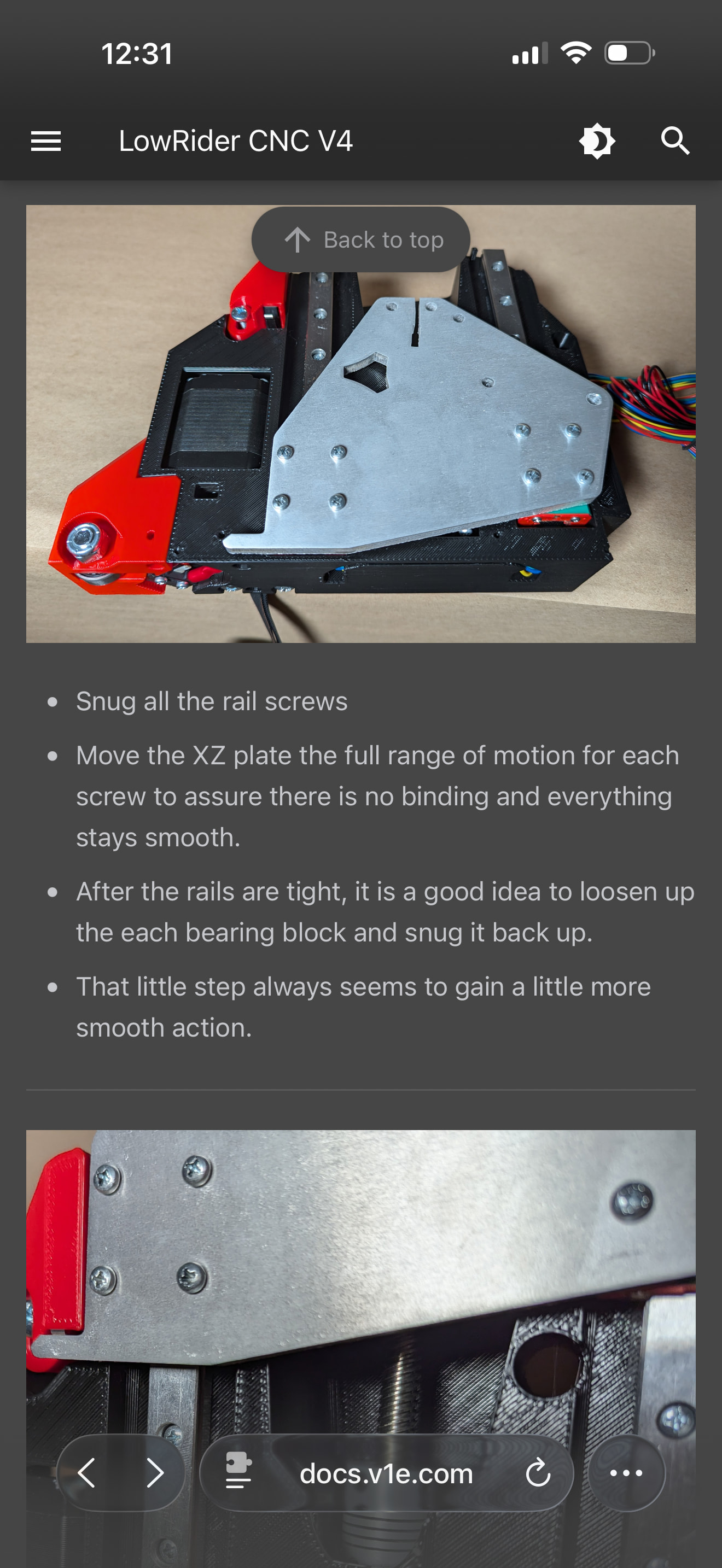
Where this says after the rails are tight, loosen the bearing blocks and snug them back up - does this just mean loosen the aluminum plate from the bearing blocks and tighten the plate back up?
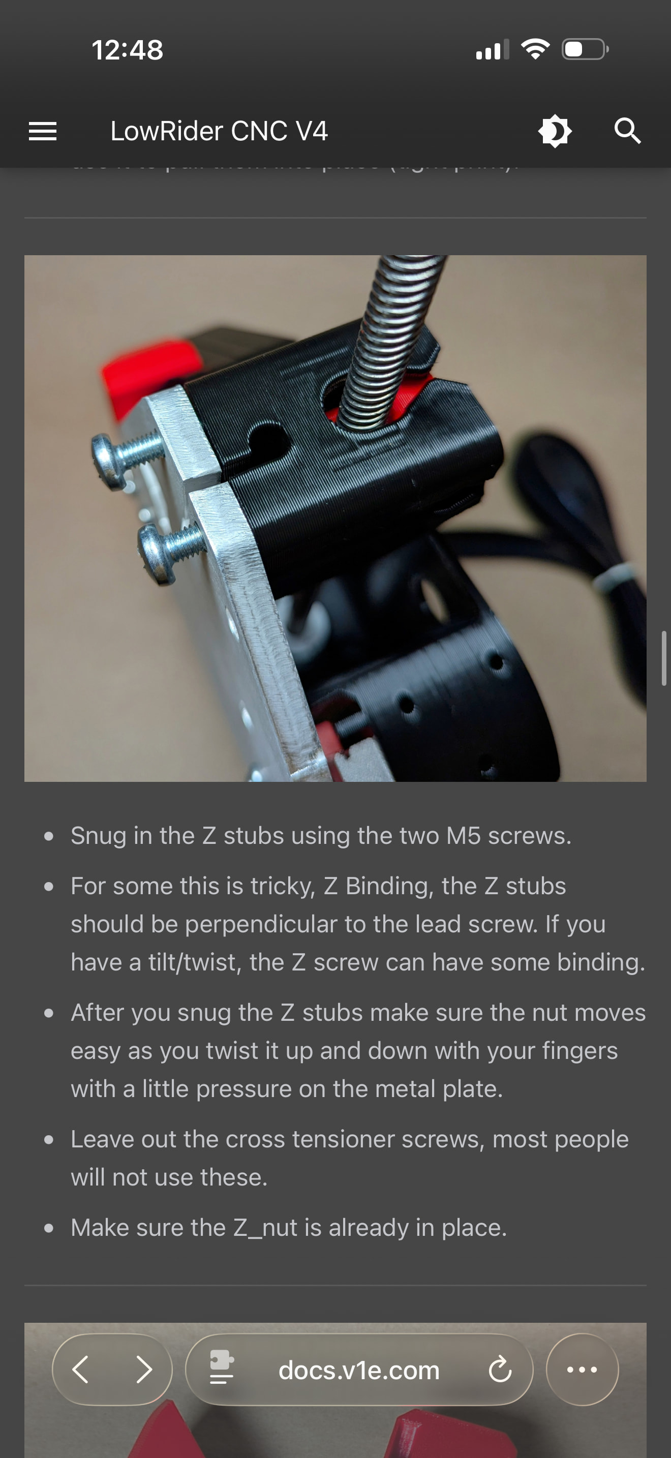
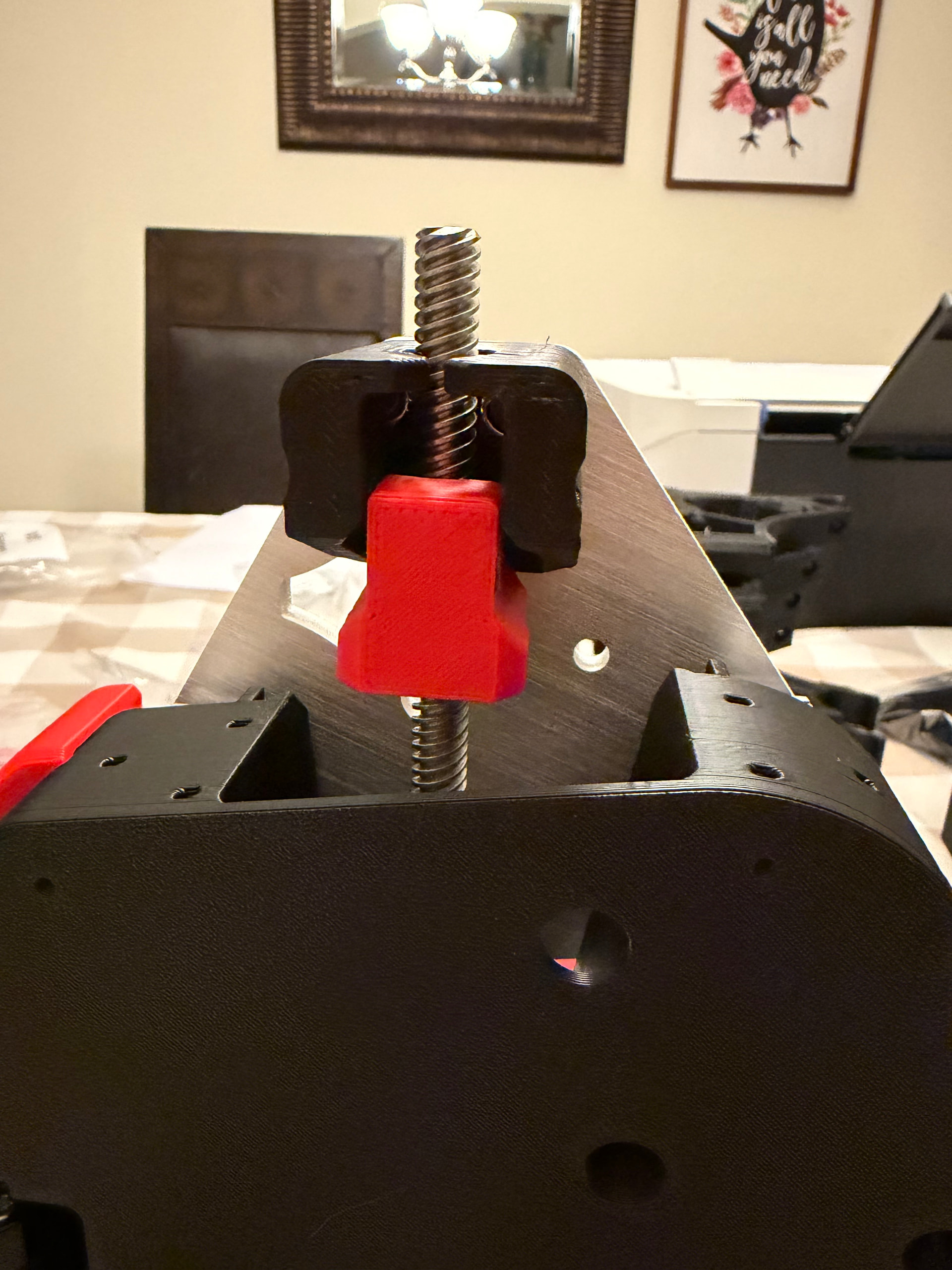
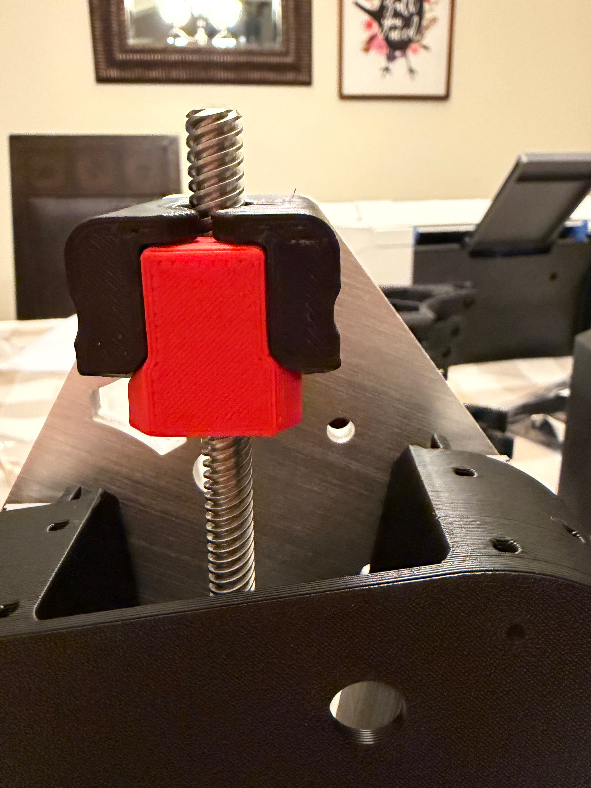
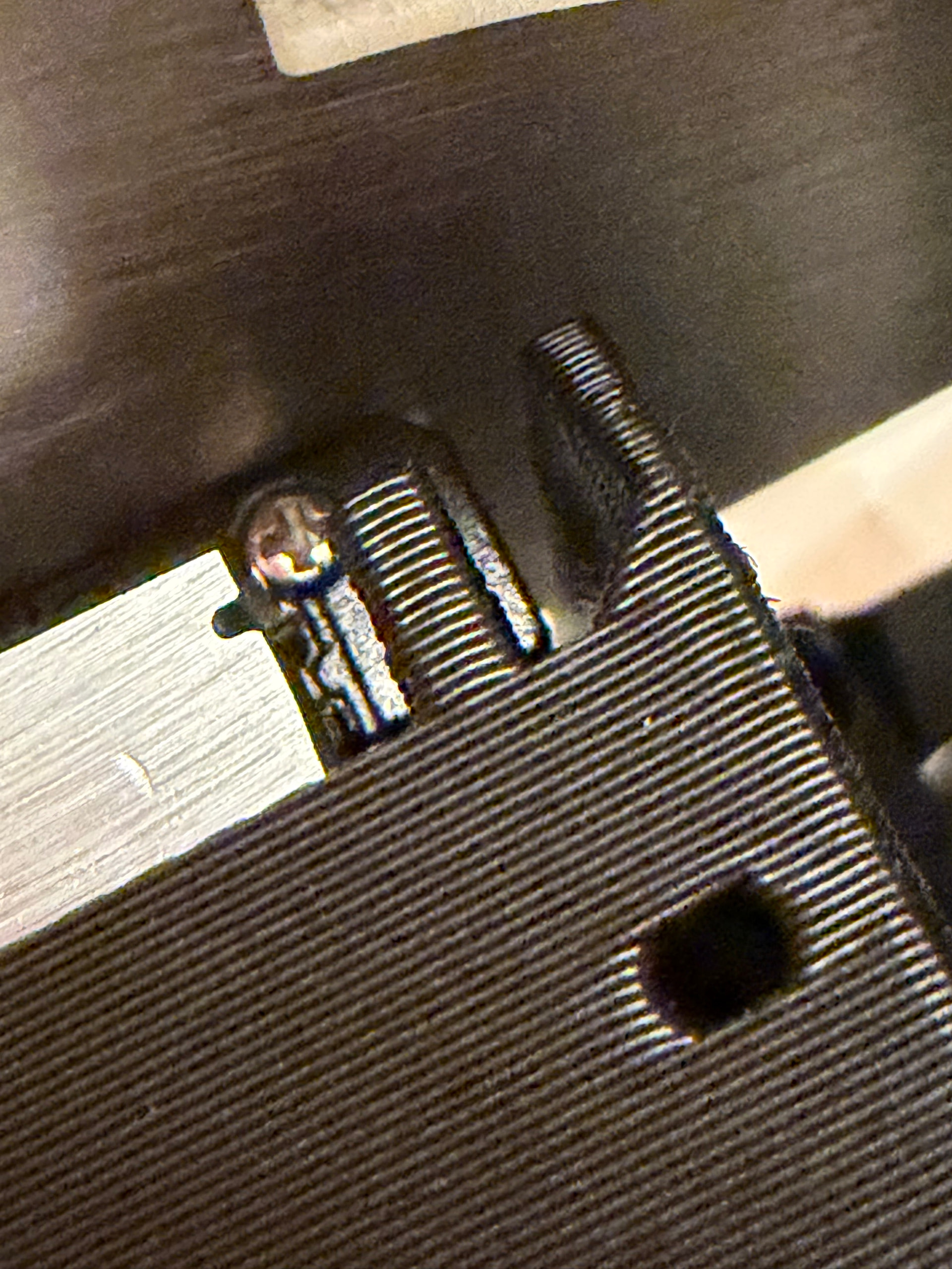
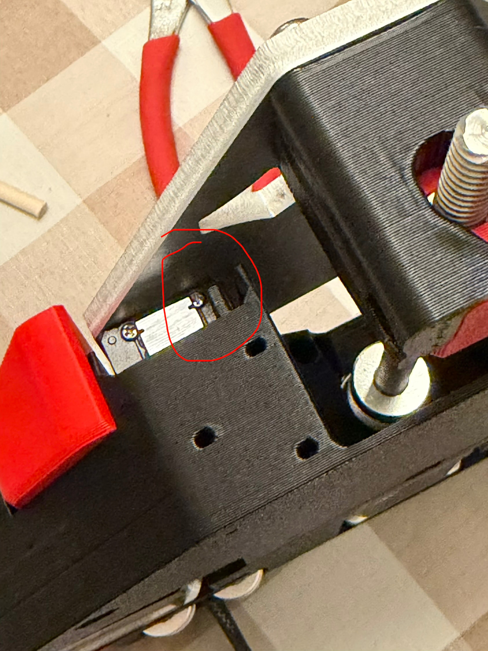
Where this says “after you snug the Z stubs make sure the nut moves easy…” — I can twist the Z screw by hand and get plate movement, but the Z nut doesn’t stay in the “pocket” of the Z stubs. Based on fit, I assume it is supposed to. Is this what the cross tensioner screws mentioned are supposed to prevent? If so, what/how do I do that? I have a couple pics of my current build of this step:
3 - As shown, my Z stubs are black. However, in my order, there seem to be 2 red printed parts that look just like them - did I receive 2 extra Z stubs by mistake or was I supposed to use the red ones and these black ones are for something else?
Both of the printed sides, at the top just above where the rails attach, are these black nubs. Am I correct to assume these are just from the printing of the parts and unimportant? I hope so since one already broke off…
Anyway, sorry for the long post and probably silly questions but I really want this build to be better than the LR3. Thanks in advance for the help!
The bad news is that nub you broke is the physical stopper to keep the blocks from sliding off
The good news, mine have broken for years.
The cross screw, I have mine in place but almost fall out loose. They cause problems when they are too tight and the general guidance is to remove them. Because mine haven’t caused me any issues, I haven’t bothered taking them out. They aren’t need though. If gravity stops working, there are still other contact points that won’t show you too pull the gantry up and off.
Just push the “i believe button" in your head and keep going. Looks like you’re well on your way
The kit you sent me to take to SMRRF had both red and black copies of those. I think I reported it at the time, but maybe in the rush to prepare I didn’t.
For now, I’ve put screws in the Z stubs to hold them into their pocket - even at this point if I manually turned the Z screws sometimes they’d come out a little. I didn’t even put a nut on them for now - the screws are just there to keep the stub in its pocket. Maybe when everything is done they can’t accidentally come out? I’m still worried I did something wrong on those…
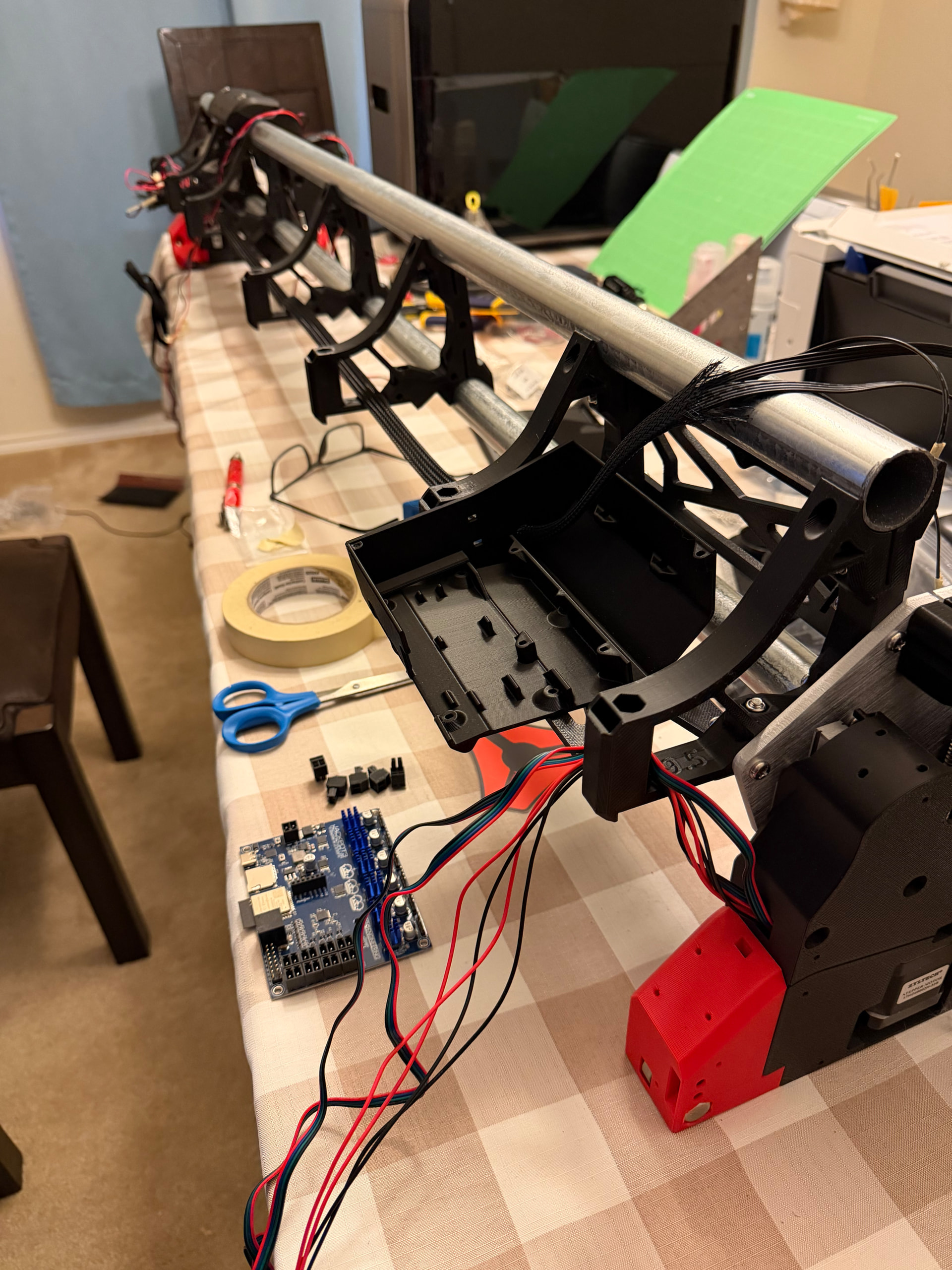
I’m on to wiring. It looks like a mess right now, but I’ll clean it up when I get it connected. My current questions are on the Jackpot3 and I feel dumb.
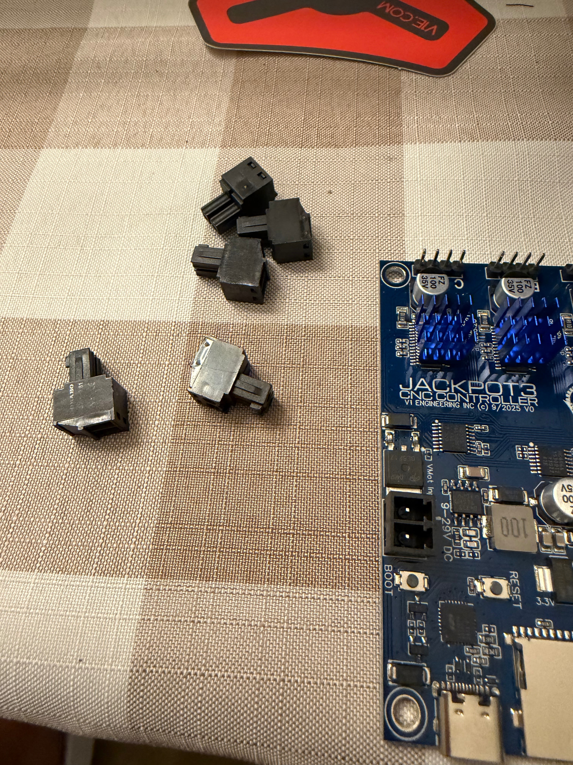
What are these for? I see where they fit into the outputs on the right side of the board - do I just plug them into the appropriate column (I assume the 24v since I think that’s the power bank that shipped with my order)?
2 - speaking of power, here’s where I feel even dumber. The power brick I received has a barrel connector, but the Jackpot3 does not. What am I missing?
Just remember to take them out. Some people make mistakes early on, and using them can stretch your couplers. When you get more familiar and if you feel like you need them for something, you can use them.
1- power input and 4 optional outputs (no need to plug them in if you are not using them).
2- You need to cut the barrel jack off, the braided section is the negative. I have a picture to add to the instructions but it has been a hell of a week.
You cut the barrel connector off, strip the wires, crimp on some ferrules, then put the ferrules into one of those terminal blocks. Then plug the terminal block into the jackpot.
Barrel connectors are crap for reliability in this environment, but it’s way less expensive to buy them stock with the barrel connector than to custom order without.
I actually thought I’d need to cut the barrel connector off, but since it wasn’t mentioned anywhere I knew as soon as I did I’d be wrong. So cut it, wire it to one of those previously mystery connectors, and plug it in. Got it. Don’t use the other 4 unless I need to connect something there.
My LR3 had a touchscreen thing that sat on top of the control board case - is there something like that I need for this build that I should have ordered?
Thanks for all the help guys - I’m done building for the night (have to go do my actual job bleh) but hopefully this weekend I’ll be close to first tests.
Quick question on the power - I cut the barrel connector off, but am clueless on ferrule crimping. Amazon has all kinds of crimpers of various sizes? with 1000+ connectors - anyone know or have a link to which one I need? Nothing extravagant since this is all I need it for.
As far as power for the router, is it best to connect it to an extension cord and route that along the rails and out the Y_min side? I don’t want it to potentially catch on anything.
Other than the power, I have my wiring done. Ordered a vacuum hose from the link on the instructions page, so that’ll go on in a day or two. I ordered 10 ft, but I’m thinking I need more - what is recommended for a full sheet setup?
Disassembled the rest of the LR3 table setup to temporarily use it for the LR4. Hope to get the Y rail and belts done tomorrow.
If you’re willing to look after the screws for the first bit to make sure as the stranded wire birdcages that it doesn’t loosen up. It’s not the current/power that is the problem, it’s the potential intermittent circuit.
You don’t really want your board randomly resetting (which is a thing members have reported), or arcing from an intermittent connection.
A ferrule kit is all of $24, and that’s really how everyone should be doing wire terminations for stranded wire.
I got my crimping tool, got the power done. Ordered some more wire sleeves, wiring is done and “ok” looking. Ordered 20 ft vacuum hose from the provided link. Stretched it out, it’s 16 ft at best, but should do the trick. I don’t understand what the instructions mean about grounding it “with the ground port from your power source”. I’m also a little concerned when I manually move the core back and forth on the rails. At the very extremes, I feel a tiny bit of tension caused by the vacuum hose. It’s not because it’s too taught, just a little resistance, particularly at the X maximum. Also, when the core is at the min position, when moving it back towards the max, sometimes the hose ribs rub on each other as it unfurls, causing some tension. Once I get it operating I’ll see how much of a problem these things are.
In the meantime, I built the $200 LR4 table to replace something similar I had devised on my own for the previous LR3. Honestly, it didn’t come out that great, but I’m hoping it will be good enough at least in the beginning. It didn’t help that I shot a nail from the brad nailer thru my finger lol. I’ve been a woodworker for 7 years and that’s my first accident.
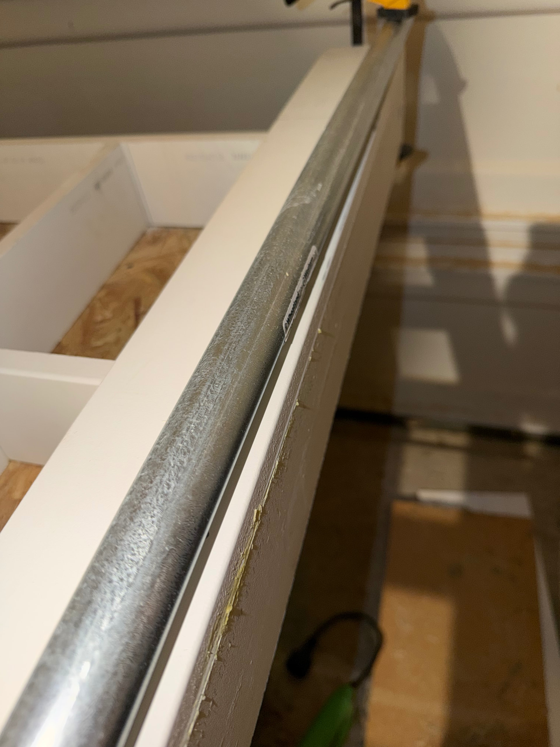
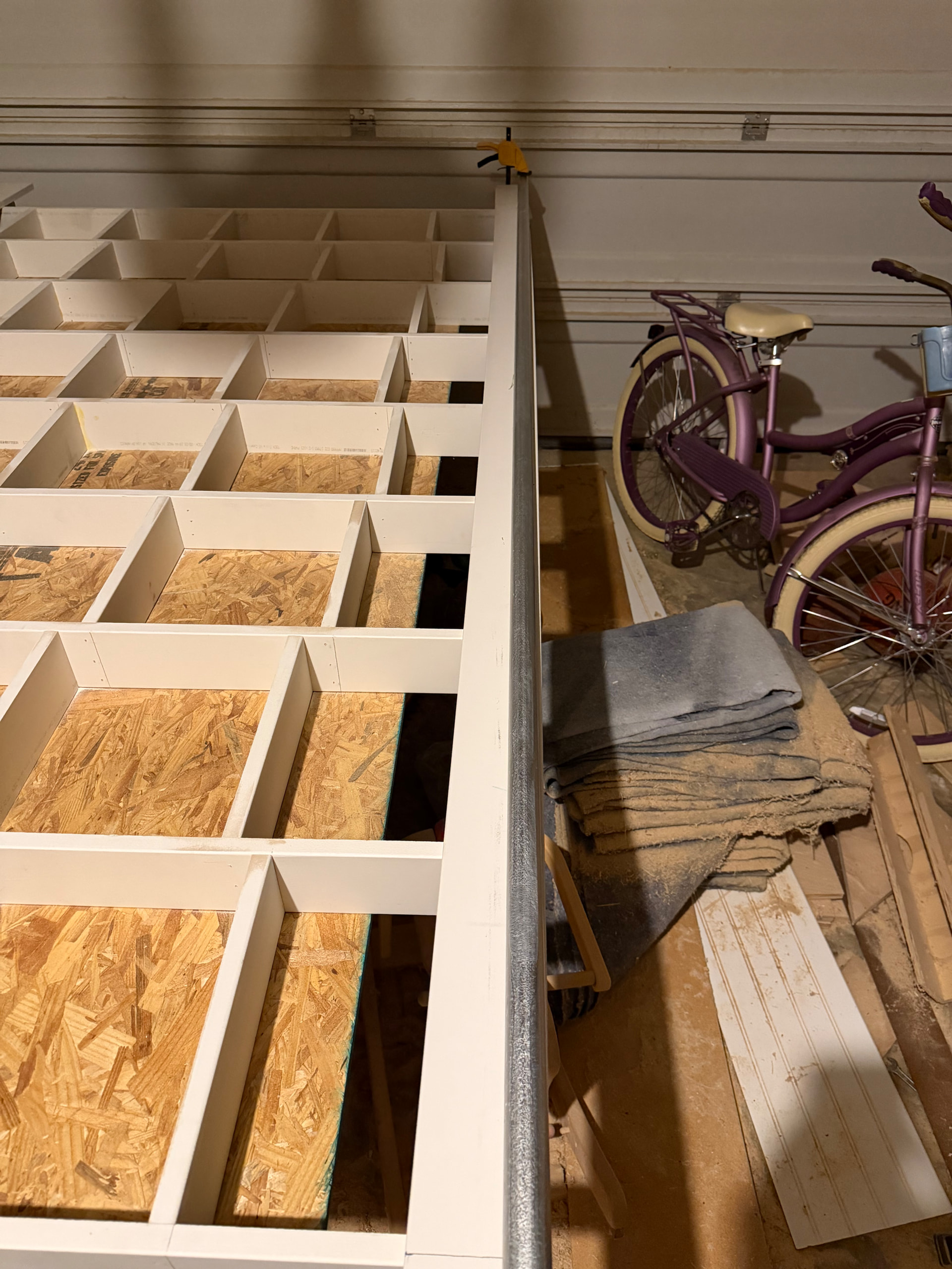
My new question now - my Y rail seems to not be perfectly straight. I clamped the 1” emt flush with the min and max edge, and you can see about an 1/8” of white showing in the middle portion:
So what’s the best method for mapping out and attaching this rail and its holders to ensure the straightest line possible? I feel if I put the Y min belt holder aligned with the right edge, and follow along the right edge, I won’t end up with a straight parallel-to-table rail, but I’m kind of at a loss for how to approach this. Anyway, I’m sure I have more questions but no one wants to read a novel, and you guys have been awesome so far - hopefully you can help me get over the finish line. Thanks!
edit: I mean my Y rail built for the table is apparently not straight, not the actual emt tubing (although who knows maybe it’s not straight too)
I agree with spsully. A string and a nice ruler make it simple to check each block without touching the string. It gives you a surprisingly accurate rail.