I mean you could set up a bunch of lasers and run out sensors and do a ton of math….. or just your a string and push/ pull as you tighten the screws so you get it straight.
There is also your belts, but it’s easier to just use a string now instead of waiting and playing around with the belts
Ok good news, bad news. First, my X spars apparently are not perfectly flush with each other. I haven’t nailed the Y runners into each spar yet, just the min and max ends. By clamping in the middle, I can nail the Y runner into the X spar and reduce the gap down to probably less than 1/16”. I’m still confused on how using a string will help too much - if I pin it at the min and max ends and see that in fact my Y runner is bowed, are you saying just to trace a line along the string and follow that for placing my Y rail?
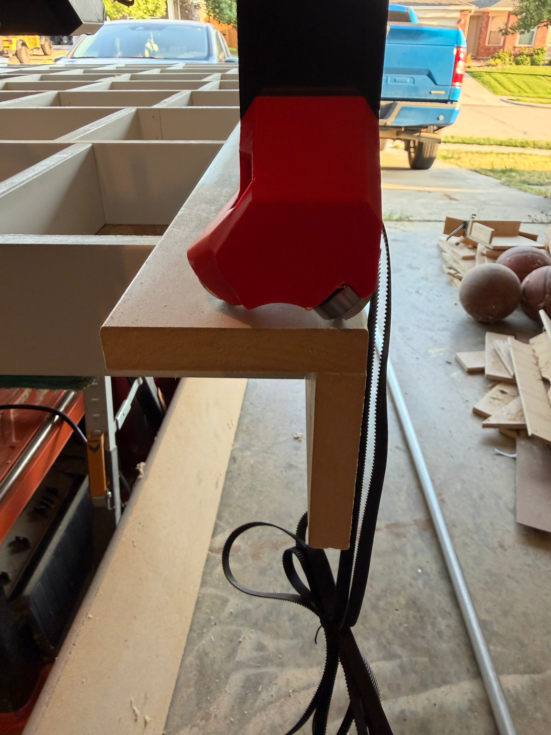
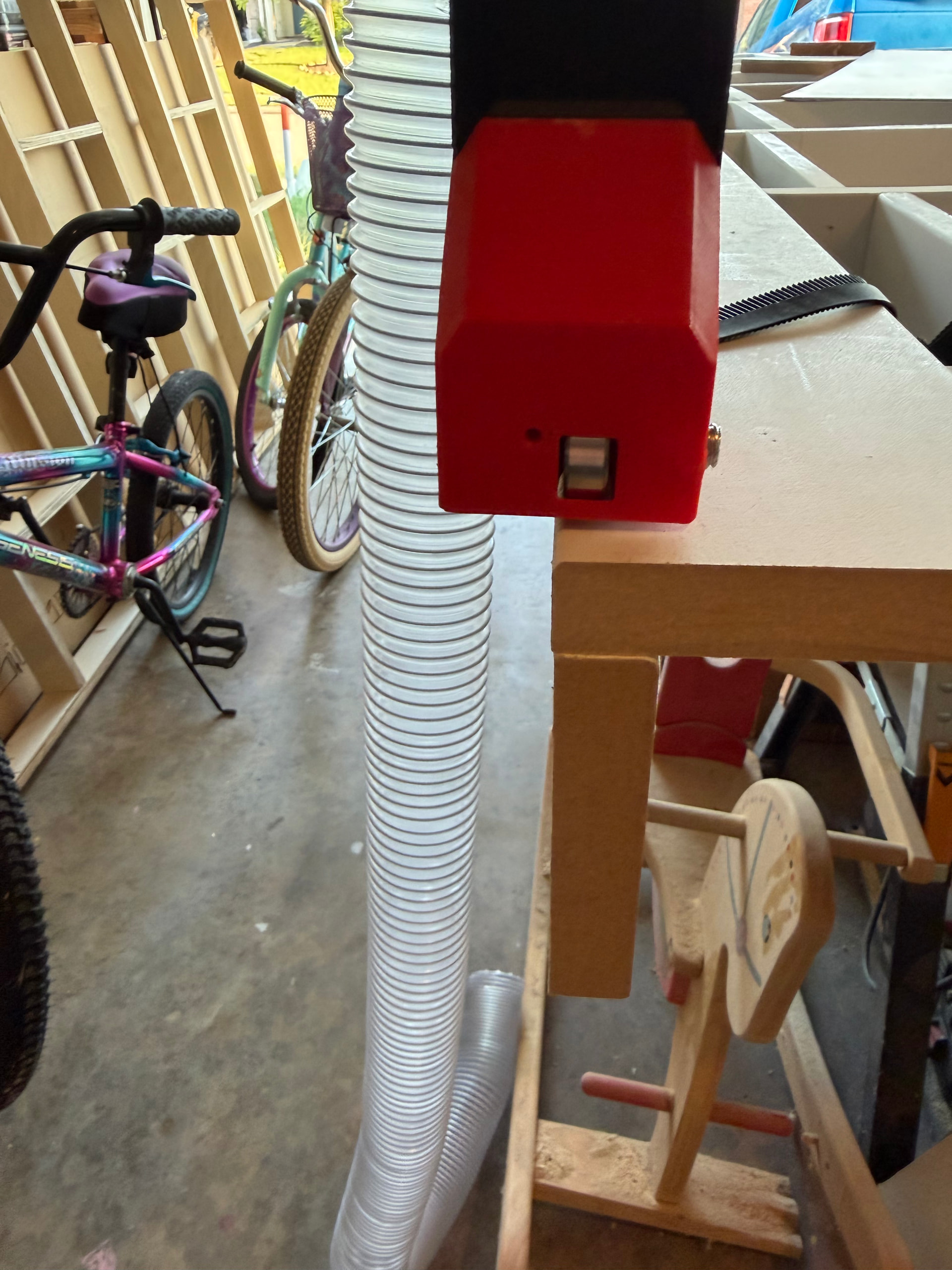
Anyway, bad news is in my infinite wisdom I guess I cut my X rails (the emt tubing) at usable cutting length of 50” thinking that would give me enough room for a full 48” sheet cut.(actual length is 56 5/8”) When I built the table, I followed the dimensions listed, as I knew it was for a full sheet table. Leaving me with this beauty:
So now I either have to do some disassembly so I can cut the X rails down to whatever the calculator says for 48”, or take off the Y min runner and “pad it out” approx an inch or so. I’m a genius
It’s also 95 degrees today so I think I’m done for the evening. Fun times
You’re saying go ahead and attach the Y rail along the outside edge of the Y runner with all its brackets and then see if the machine still has overhang on the min side? I can do that but it doesn’t look hopeful at all based on what I’m looking at
How have you attached your Y rail runners to the table? If they are hard against the side of the table, can you carefully prise them off and re-fix with a 3/4” packer block to effectively making the runners further apart?
@dougb Yeah, they’re only Brad nailed on currently at each end, so that’s what I was thinking - pry them off and put another runner or some blocks to push them out. I’ll get my table stretcher lol. It’s either that or try to take the X rails out without having to undo too much and cut them shorter. Neither solution will be fun, so I’ll figure that out tomorrow
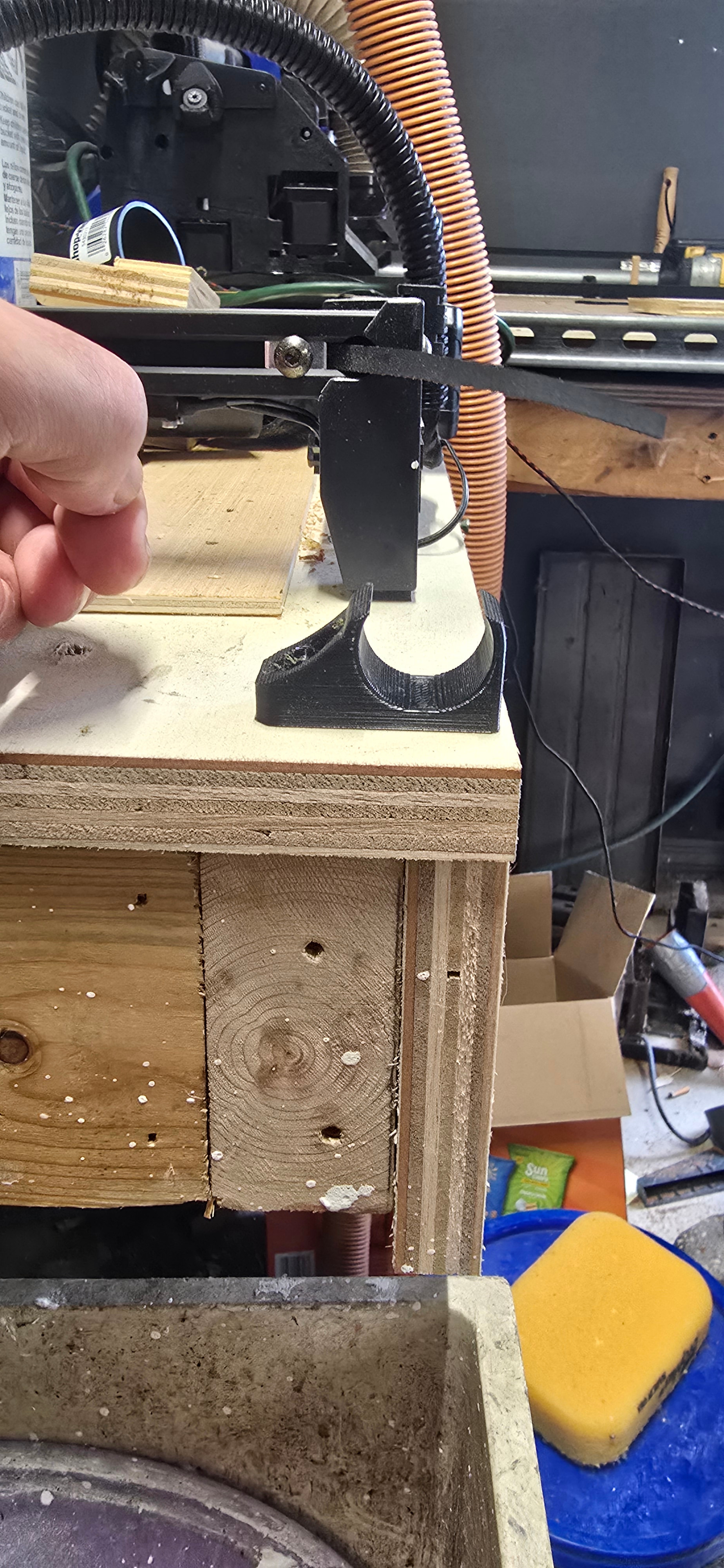
By adding a plywood face to the side of the table, the bracket is now supported and ¾” past the structure of the table. You buy that extra distance in cheap work around.
You COULD do it on both sides, but personally I’d rather do it under the rail so the wheels size still has a uniform surface
Ok, real life got in the way the past week or so, but I did make progress. Table wide enough now. Got the Y rail and Y belts attached. X belt attached. In theory it’s ready for me to turn it on and drive it around, but I’m a little concerned with the X movement of the core. It requires a little force to move it, and I get some clicking noise that I can’t tell if it’s the belt slipping or what. I made a couple short videos but apparently I can’t post them here. I know it’s virtually impossible to diagnose without seeing/hearing it, but anything I should look for first or just fire it up and see what happens?
i’d be investigating this. perhaps loosen off the tensioning bolts that tighten the core onto the gantry. it should move from min to max smoothly with little force. those bolts only need to be tight enough to take out any play/wobble
First, be careful if you’re moving the machine around by hand while the machine is off because the stepper motors become generators when moved with no power. The EMF from that can blow stepper drivers in your controller if you move it too quickly.
You could unplug the X axis stepper from the controller while the machine is off, then when you move the X axis around does it feel/sound different?
As Marty mentioned, check that you core isn’t too tight. It’s really easy to over-tighten and then crack a core so be really gentle.
Me approach is to only just snug up the bottom bolts til the bolts don’t rattle in the holes.
Then tight up the top bolts in the core until they either don’t rattle in the holes or the bearings just touch the EMT rails. It’s only small adjustments, less than 1/8 of a turn at a time.
Then I rock the core, and if it is wobbly I’ll only very slightly tighten the upper bolts say 1/16 of a turn alternating between them and repeating the wobble test.
Most folks overtighten the bolts through the bearings.
Yeah the whole thing moved really smoothly until I attached the X belt and tensioner - previously the belt was run thru the core but not attached on either end. That’s the only reason I’m not sure it’s over-tightened bolts for the bearings that keep the core on the rails. I’ll loosen them anyway in the morning. My X belt seems about right too (at least compared to the old LR3) so that’s why I’m a little worried. I’d hate to drag this all out and fail at the finish line. Also, thanks to everyone for the continued help!
Do the test where you unplug the stepper from the controller first, before you do anything else.
Check the belt path through the idlers and toothed pully on the stepper motor to make sure it isn’t misaligned or binding somewhere as the belt goes through that part of the core. If everything is OK, and the motion is smooth with the stepper unplugged from the controller. then it might just be you feeling the drag of the stepper as it finds steps when not powered.
Video showing how the axis looks and sounds might be helpful for diagnosing this as well.
another thing to check… i had some weird missed steps on my x axis when i first assembled my machine. turns out i manage to loop de loop the belt inside the core!
Did some troubleshooting today - if I remove the X tensioner, the core glides smoothly, so I put it back and decided maybe that’s just how it is when under tension and decided to plug it in for the first time and see if I can drive it around. The good news is- movement on the X axis seems to be fine! No cuts or anything yet, but it moves left and right just fine. Now…
My Z works, but the up button is down and vice versa. Is that just unplugging it from the controller and flipping the wire around?
Y is a bit of a problem. The Min (left) side seems to work, but the Max side stayed put. Got the machine nice and crooked - so drove it back and the Min worked and got back straight while the Max side remained unmoved. I don’t want to unplug wires willy-nilly lol so before I drive it again thought I’d get some professional advice
Yeah I read further, flipped some wires, seems to drive as expected now. Gotta figure out the browser and commands a little better, but yay homestretch!
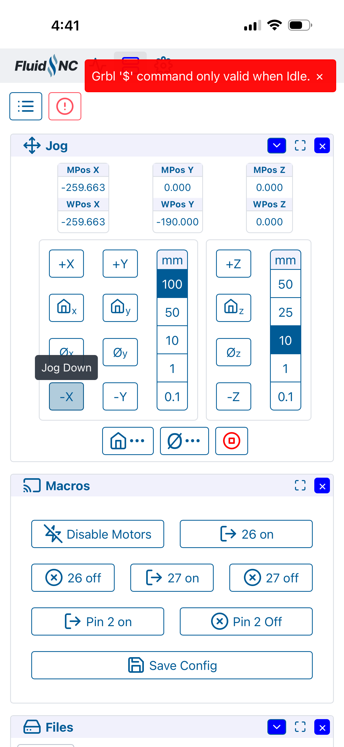
“…command only valid when idle” like it’s still trying to do something even though it seems to be idle. Even if I press the stop button, nothing seems to work other than unplugging the whole thing. I’m sure this is something dumb I’m missing…
I’m also having an issue when trying to save my steps for y and x axis. Default is 50. By my measurements, I need 50.3. When I change the numbers in the config, I click save and the screen insta-refreshes. I reset the board. If I scroll, the numbers reflect my change. However if I refresh the info or turn the board off and back on, the numbers revert to 50. It seems like the save isn’t actually happening.