The FAQ says smaller is better for all axis for better accuracy. For some projects I have, I need at least 24" x 24" for XY for routing, so I have to try to make that work at least. For routing, I wouldn’t need much height, since I am mostly planning to just cut out of plywood, as I think most people do, but I’d like to keep my options open for 3D printing. When having a higher Z axis, I assume the reduction of accuracy increases further away the spindle hangs down from the gantry, and also from the wobble of the corner legs. Could this be accounted for by making the conduit legs as short as possible, but raising the machine up on wood supports or something else more rigid, and also by having a bed that I can swap out for a high or low one, with the high one being high enough so the spindle doesn’t have to lower more than an inch or so to cut, and the low one being low enough for full height printing when needed? Or am I way off on where the reduction of accuracy comes from?

It can be done that way, some even swap out there Z axis since the parts are cheap. It really comes down to why not just buy/build a 3D printer? If you want to print large things there are all sorts of issues, A lot of people use this to print bigger things, but if you are going through all this just to print benchy’s you are going to regret it every time you cut something out. Another option is a second build. Not to be a huge downer but decent printers are just ridiculously cheap, and they will print much faster than a CNC with 8" of tubing and a stepper swinging around at the top.
I guess to summarize is only do it if you are going to print giant things with a large nozzle and understand the issues that you need to overcome in doing that (mainly giant flat heated beds are not easy to do). Anything that can be printed on a standard 8x8x8 printer should be.
It really comes down to why not just buy/build a 3D printer?It was hard enough convincing myself, and then my wife that I should pull the trigger and build a MPCNC. The biggest appeal to me, and part of what I used to convince her, was that it could be used as both. While I could build a 3D printer, it would be another $250 or so in motors and controllers. I could buy a small one for around $150, which I debated doing rather than buying just the 3D printed parts for the MPCNC, but then a friend of my wifes said he could print the parts for me, so that was again, another selling point, was that I was getting the parts for free, not even paying for filament.
I guess to summarize is only do it if you are going to print giant things with a large nozzle and understand the issues that you need to overcome in doing that (mainly giant flat heated beds are not easy to do).That's part of the fun, and the interest... seeing where I can push the limits. I love reading the stuff about people doing steel. Not because I want to work with steel, but because it's something that you didn't think was possible with your design, and now it's being figured out. I love that part of things. I gave a talk about computer security at my kids high school a little while back, and at the end, the teacher asked me what the kids could do to get started in security research. I told them, the first thing you do is need to change your mind set. When you are given a list of rules and limits, don't accept them. Instead, look at the list and look for a loop hole, or how you can push the limit. That's what the guys did that started cutting steel. That's what the guy did that hooked up a plasma cutter to it. That's what you did when you decided to make a CNC machine that used electrical conduit for rails. That's the coolest part about the whole thing to me.
Okay you passed the test!
So, I’ve had to reply like 3 times now. Had a couple errors from Cloudflare, and when editting to correct, it just removes my post. In one case, it took me to a URL where I could see my post, but the background was red, so I assume it was “deleted”. Anyways… third time…
https://www.v1engineering.com/forum/topic/minimum-z-height/In that topic about minimum Z axis, the poster said his conduit was so short, and the leg pieces were flat against each other. You said it would give a cutting area of 2.75". So, I am thinking I can make the shallowest table depth be 3", and have "shelves" where I can slide it in for different depths. Any thoughts on whether or not I should go with 3" steps for 3", 6", and 9", or use 2" steps for 3", 5", 7", and 9"?
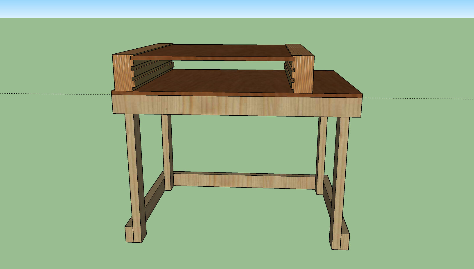
I am thinking a table like shown in the attached picture. I already built my base table, so I would just need to glue up plywood and do some cutting and routing to make the uprights. I figure if the MDF shelf/table bows, I can cut some block supports to put under it, or run something threaded up through the table that I can adjust up under it as feet.
I’m not certain that top 1/4" bit of wood above the 3" position in the photo would last long, so I might have to make the top level flush to the top, and find a way to hold it in place, since the friction of the shelf in the dado would do it on other levels.
[attachment file=“CNC Table.png”]