Hi everyone!!
I am wondering if someone can help with some issues with the programming…
I am trying to make the PWM ac Dimmer turn on when I send print and turn off when finish printing, I want to use the pwm port Fan-2 or better idea?
I’m using the Rambo 1.4a board and the PWM AC Dimmer the V1enginnering 
I will appreciate any help!! Thanks…
The PWM AC Dimmer in the V1 store takes input in the 3.3V to 5.5V range. The fan pins are 12V…kinda. For the fan pin pairs on the Rambo, the PWM is implemented on the ground side, not the 5V side, but given that you have ground, PWM, and 5V you need to connect to the dimmer board, that does not help you. So here are two choices.
- In pins_Rambo.h, redefine one of the fan pins to a 5V pin. My first choice would be pin 46. Pin 44 is an alternate choice. After redefining the pin, compiling, and flashing the firmware, you can use M106 and M107 to control the pin you’ve reassigned to the specific fan. Here is the section of the file in pins_Rambo.h that assigns the three different fan pins:
#ifndef FAN_PIN
  #define FAN_PIN                              8
#endif
#ifndef FAN1_PIN
  #define FAN1_PIN                             6
#endif
#ifndef FAN2_PIN
  #define FAN2_PIN                             2
#endif
- A second choice is to use M42 (Set Pin State), to set the PWM of the pin of your choice. This choice does not require you to modify the firmware. Again, pin 46 and pin 44 would be my first choices in pins. It is possible that pin 44 and/or pin 46 are not set to OUTPUT by default, so if your g-code is not changing the output voltage, you will need to add the follow once at the top of the g-code file before you set the PWM of the pin.
M42 P46 M1 ; Set pin 46 to OUTPUT
If you have a couple of Dupont wires you can put on the pins, and a multi-meter, I’dcarefully check the pin voltage output using the g-codes of your choice before hooking the pins up to the dimmer.
As for the location of pins 44 and 46:
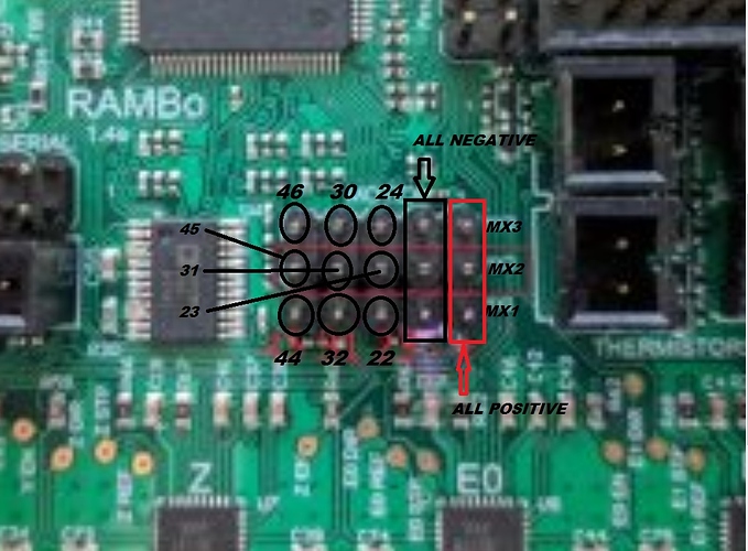
Note that pin 45 is assigned to the laser in the V1 version of the firmware.
Thank you very much, I can’t wait to try it. I’ll tell you how it went
Hello again, last night I was trying to get this to work and I only managed to get them to turn on but manually, am I supposed to do it automatically, or is there any other way to do it?
I don’t know how to program and if you could give me an example of what I should do I would really appreciate it
I’m not sure where you are in the process and therefore what problem you are trying to solve. Does manually refer to turning the fan on with a display, or with sending g-code from a g-code sender, or…???
Now that I think about your question, I’m unclear of your goal. Do you want to be able to author spindle speeds in your CAM and have them translated to specific PWM values to drive a router? If so, you need to approach the problem a bit differently.
Can you provide:
- The goal for what you want the PWM dimmer to do when working.
- What tool you are using for your CAM.
- What tool you are using to send your g-code.
- Are you comfortable modifying values in the firmware, or is that something you want to avoid?
If you have the fan g-code working, it is relatively simple to have fan g-codes automatically added to your file to turn the dimmer on to a single specific PWM setting, and turn it off at the end of the file. You will need to edit the PWM value put in the file in your CAM or g-code sending solution each time you want a different PWM value. But if you want the PWM values to be driven by the spindle speed you set in your CAM, then you will need to make some small firmware changes and use a different pin.
Hello, excuse me for not explaining myself well, besides the programming my English is not good, with manually I mean that with the button on the screen, what I did was enable redundancy with fan 0 to Fan2 with pwm, thus turning on fan 0 I activate the pwm output of fan2, but it is not what I want to do 

The intention of this is that when I send the g file to print, the PWM dimmer turns on the AC output and to turn on the router and when the file that was sent to print is finished, turn off the PWM AC, thus turning off the router, I am not interested in handling the router speed
I understand when you tell me to put the m106 and m107 commands in the g-code file, I did the test by modifying the file and it works, it turns on when printing starts and turns off after a few seconds, but how can I make it do it without modifying that file, let it be part of the programming in the firmware
To give you specifics, I need to know what CAM software you are using and/or what you use to send your g-code to the control board. Most CAM and g-code sending solutions have sections called something “start code” and “end code.” You can put whatever you want into these sections and the code will be inserted automatically. This includes ESTLCam, Fusion 360, Repetier-Host, and Lightburn. You would put your M106 in your start code section, and your M107 in the end code section.
In EstlCAM for example, you will find the section in Setup/CNC Program Settings/Texts. In Repetier-Host, you will find it in Config/Printer Settings/Scripts. You want to put it in either the CAM or the g-code sender, but not both.
Ok, I am not using any of these programs, just take the crow-test file to test it, I read the firmware code with visual studio, sorry if I give much trouble but this is all new to me, but I am very interested in learn, I really appreciate you taking your time to help me. I don’t know if what I’m telling you makes sense to you, excuse my ignorance on the subject
I will follow the path that you indicate to me as best as possible so as not to cause so much inconvenience
I put the crow test file on a USB and I send it to run directly from the screen, I feel really lost 
There are a few things here.
Just Turing a spindle on and off is much easier with something for that. Iot relays or an SSR.
The board you bought is made for controlling the speed. Without the control part you will need to add a few commands to your m106/7. You might need to specify a speed (255) for on, and m107 should work as is.
These will go, like Robert says, in your start and end gcode, have a look at the milling basics page for some examples.
Hello, good night, and how could I just turn the fan on and off regardless of the temperature, but by modifying the firmware, is that possible? You tell me that the board only controls the speed and that it goes from 0 to 255 where 0 is off and 255 switched on.
If I turn on FAN 0 on the board and use redundancy for Fan- 2,
enabling this line of code, I manually turn on fan 0 and turn on fan 2
#define REDUNDANT_PART_COOLING_FAN 2 // Index of the fan to sync with FAN 0.
pwm pin 2 is enabled and sends a signal to the attenuator pin from 0 to 5 volts, turning on the current output, I just want to know how to turn on the fan 0 regardless of the temperature by modifying it in the firmware, but I don’t know anything about programming: -(

None of the fans turn on at any time, I must do it manually, you who know programming could tell me if it is possible?
There is some confusion here. You can already turn the fans on without temperature. You don’t need to mod the firmware to do that.
It is what I have tried to say but I do not know how to program and I am learning in the assembly process, what I do is that I turn on Fan 0 manually from the screen and in the firmware I put redundancy towards pin 2 pwm of fan 2 thus activating the AC Dimmer output, but I want it to do it only when sending the printout, please help me with the code or the correct way to do it.
Another thing is my English, it is more complicated for me to understand the translations and to explain myself well, but I try
What little I understand about how the AC dimmer works, it needs to be powered with 5v, ground and PWM (where to activate the triac and power the AC output you can give 0 to 5v to the PWM port). Fan 0 turns on with 12 volts so it doesn’t work for me, what I did was in the Firmware activate the redundancy of Fan 0 towards Pin 2 (pwm) but that only allows me to turn on from the screen and automatically when sending print . Excuse me if I am giving you an inconvenience but I don’t know people with the knowledge for this.

note: the output of port two (pwm) gives me the 5 volts, that’s why I used that one.
I think there is confusion here plus we don’t understand what you are trying to overall…what the goal of your wiring and changes are targeting. Part of the issue might be language. Sometimes writing in another language and using Google Translate can get the idea across. For example, we don’t understand why you had to change the firmware with #define REDUNDANT_PART_COOLING_FAN 2. The M106 commands allow you to specify which fan to turn on.
As a direct answer to your question, the only way I know to turn on the fan when the control board is powered up is to put an M106 in an autostart file on an SD card.
Ryan says that the fans are controlled by temperature, that’s one reason they don’t turn on automatically when I send a print, I don’t have any temperature sensor, so I have to turn it on manually and turn it on through the screen, as I mentioned above the reason for activating redundancy was because fan 0 that I can turn on with the screen gives me 12 volts and not the 5 volts that I need to activate the AC dimmer and pin 2 pwm for fan 2 if it does.
And the intention of where I would like to arrive is in some way that the turning on of the router was automatic when sending printing and not doing it manually.
I don’t want the fan to turn on when I turn on the board, I want it to turn on when the printout is sent because it’s the way I get the 5 volts to activate the AC dimmer, I give up I don’t know how to do it
I don’t know how to program, that’s why I ask you how the code would be if it could be done
When authoring for the CNC, you will be using some tool to translate the idea/drawing/path/shape into g-code that the CNC can use. You will be using EstlCAM or Fusion 360, or FreeCAD or LighBurn, or InkScape, or a bunch more tools. Almost all those tools have ways of automatically inserting g-code at the beginning and end of any g-code files that the tool generates. So, you will be setting your tool up to insert a M106 at the beginning of the file and an M107 at the end automatically. This is how I turn my router on and off. This is not done in the firmware.
So what tool will you be using for your CAD/CAM to author your files?
I tried to use ESTLCam, but it doesn’t accept my board, Install repeater-host and that worked for me, so I’ll use that one.
So the only way is manually either with the screen or by inserting the power off and power on code at the beginning and end? I thank you infinitely for your patience