I just finished Building my MPCNC. It is a 24"x24" running mega 2560 with a Ramps 1.4 set for 32 step, stepper controller DRV8825, T8 lead screw (http://a.co/53EHKon ), and a rotozip for the spindle. Firmware is the most resent MPCNC for T8 32 step no end stops. I am running it with the LCD. The problem I am having is that the Z-axis is only moving a quarter of what it is suppose to. I set the end mill at the top of the wood and use the LCD to plunge 10mm and when measured it is only 2.5mm deep. The X and Y are good it is just the Z.
Hello. I have the same problem with shifting the Y axis. I have a single-threaded screw with a pitch of 2mm. I take the firmware and change the lines in the zip archive
/ **
Default Axis Steps Per Unit (steps / mm)
Override with M92
X, Y, Z [, I [, J [, K]]], E0 [, E1 [, E2 …]]
/ #define DEFAULT_AXIS_STEPS_PER_UNIT {200, 200, 3200, 200} // {80, 80, 1600, 500}
Then I flash it through XLoader. And as a result, nothing changes, I give the command to move by 1mm and the axis does only 0.25mm
What am I doing wrong?
Assuming you are correctly flashing your board, and assuming that your changes are have no impact, then it is likely you’ve have used an M92 g-code at some point to modify your steps per unit. Once you have modified the steps in g-code, changes in the firmware are ignored. To fix the problem, you can either use an M92 to make your changes and then save those changes with an M500, or you can do a factory reset (M502). A factory reset will wipe away any other settings changes you’ve made and saved using g-code.
Edit to add: If you have used the display to set the steps per mm, it is using M92 under the hood and therefore will cause this problem.
Good afternoon. I installed a new firmware on RAMPS 1/4 marlin and connected a laser with PWR control, 44 pin for control does not work. What could be wrong? I measured the voltage at D9 there it changes while the engraving program is running. How to make control from 44 PIN? thanks in advance
I’m not sure why you are seeing voltage changes on D9. Are you running the latest version of V1 maintained Ramps firmware (515)?
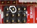
In the latest Ramps firmware maintained by V1, the laser PWM is assigned to pin 6, not 44. If you need to make it 44 for some reason, you will need to edit the pins_RAMPS.h file. Below is the section that controls the assignment. Since there are no servos assigned, pin 6 is selected.
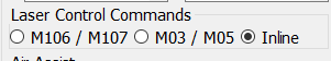
Switch your engraving software to using inline commands or M3/M5 to control the laser, then use pin 6. No firmware changes required.
It looks like D9 is assigned as a fan pin. That means your engraving program is generating fan g-codes to control the laser. If your engraving software supports it, the best solution is to use inline commands. If it does not, M3/M5 commands can be used. Both will use pin 6 (a 5V pin) for laser PWM.
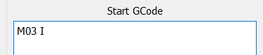
If you use inline commands, you must have the following at the top of your g-code file:
M3 I
This can automatically be inserted in most authoring software by adding it to the “start code” section.