Truing Primo
I have been up and running for a while with PRIMO recommended build size and larger steel pipe size with V1 bought parts (Except for 3D printed from a friend).
I guess what I am wondering is where to approach squaring and it is reasonable to achieve near perfect sub mm precision here? I already spent a lot of time on squaring but:
- my round cuts are taller then they are wider. Off by maybe up to 1.0 mm ish. Grows with size? Likely squaring…
- my holes tallest dimension (Vertical) is cutting smaller then spec as well. Likely steps issue?? Software?
I am not looking forward to re-squaring. So many places and I don’t have a good idea where to go now. I have already spent a LOT of time getting it as close as I could. My bases were still like 1mm or perhaps less off. I am a slight parallelogram which may be my issue.
It is really tricky with these self centering base holes as I did not drill PERFECT placed holes in the table. Is it worth modifying the bases to have L slots and flat tops at the corners and reprinting to give me a way to nudge my imperfect drills? Or is there enough slop elsewhere to fix this? I tried “adjusting the core” by turning the truck bolts, but this does nothing as far as I can tell. Its tough to feel “just tight” with these lock washers. I have tightened down most bolts to just snug but I need to check again. I have re-tightened down the belts which had seemed to have loosened. I have not really touched the core bolts yet (beyond those trucks) but nothing seems loose. I am using strong pipe-clamps for the endstops.
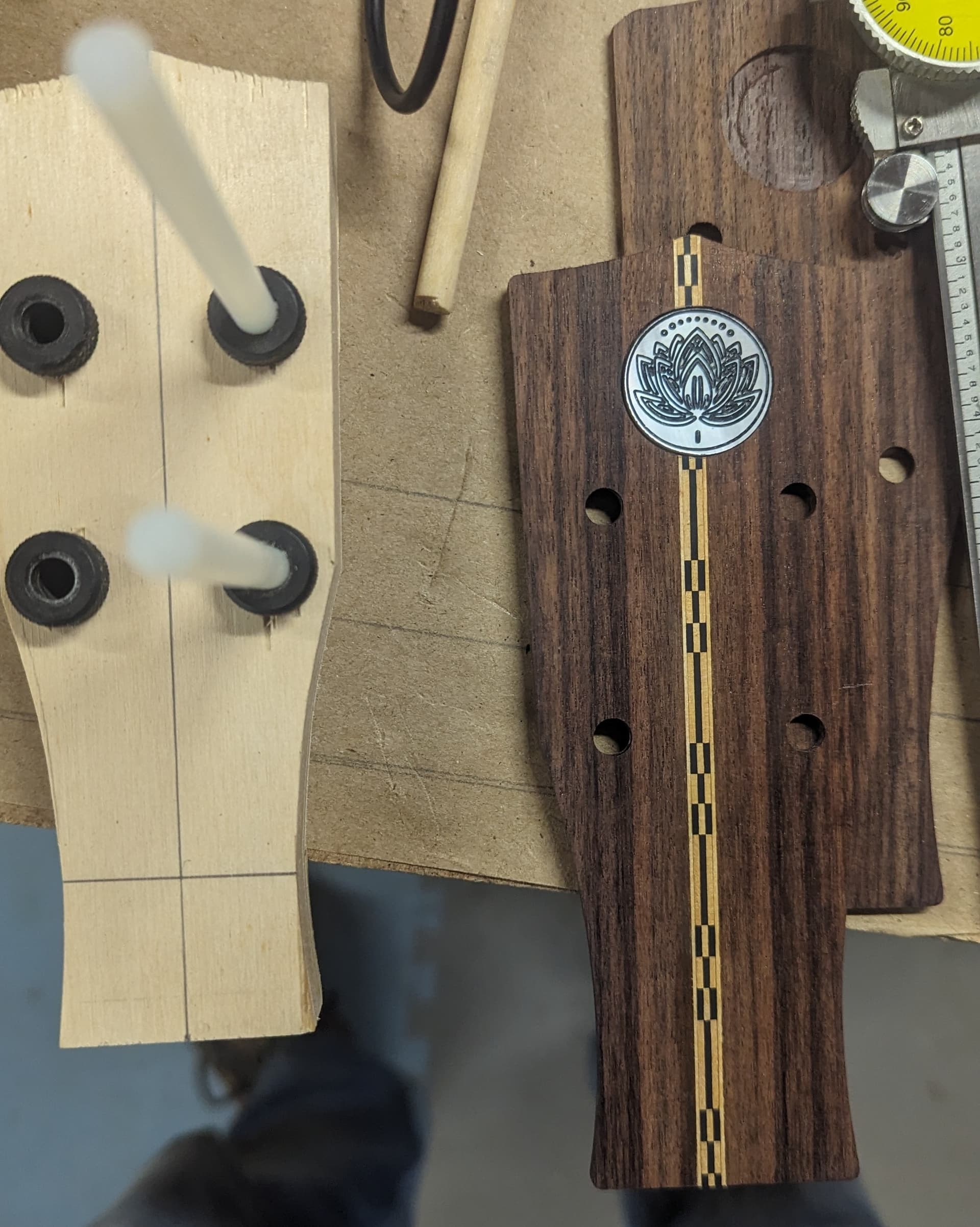
I was using a 25mm circle to evaluate with a .05 - .15mm tolerance (wider) pocket both via ESTLCAM. I was longer SSW up to NNE direction (like this: /, see pics). XY zero @ bottom left. Gaps are up to 1mm. But I suppose there may be some inconsistency here which may lead me to something being loose. I am not sure if my evaluating and playing is doing this or its just a sloppy cuts. Takes a long time to evaluate. The 25.15mm pocket is in hardwood being filled with MOP circle inlay.
I am dealing with essentially 4 mating parts that all need to be 1/4". a (1) Template cut with 4 holes 1/2" using (2) drill bushings with exactly .25 inch holes, (3) the hardwood part itself being cut with matching 4 holes, and (4) - 1/4" pins inserted to bring everything into alignment. This is how I discovered the holes are smaller then spec in the TALLEST dimension; about .0235-0.24 inch. Specified as 6.35mm in Estlcam. I could probably add some tolerance to the 1/4 cut holes to fit the too small, I just don’t like the sloppiness of it and I wonder if adding tolerance also must “scale” as designs get bigger and smaller.
I don’t know I am going to move on with my project and make do with the old school methods and I can troubleshoot this on the side as I go. SOmethings don’t matter precision wise, something’s are critical.
Not sure where to begin I guess but ill have to fit it in. Some pics.
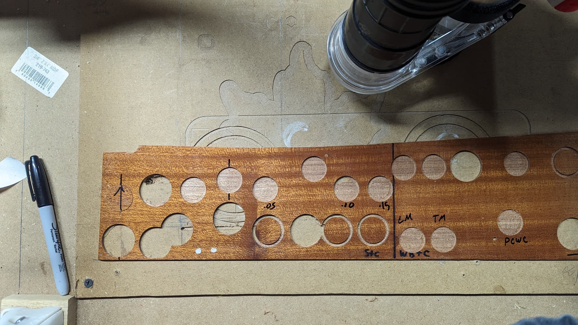
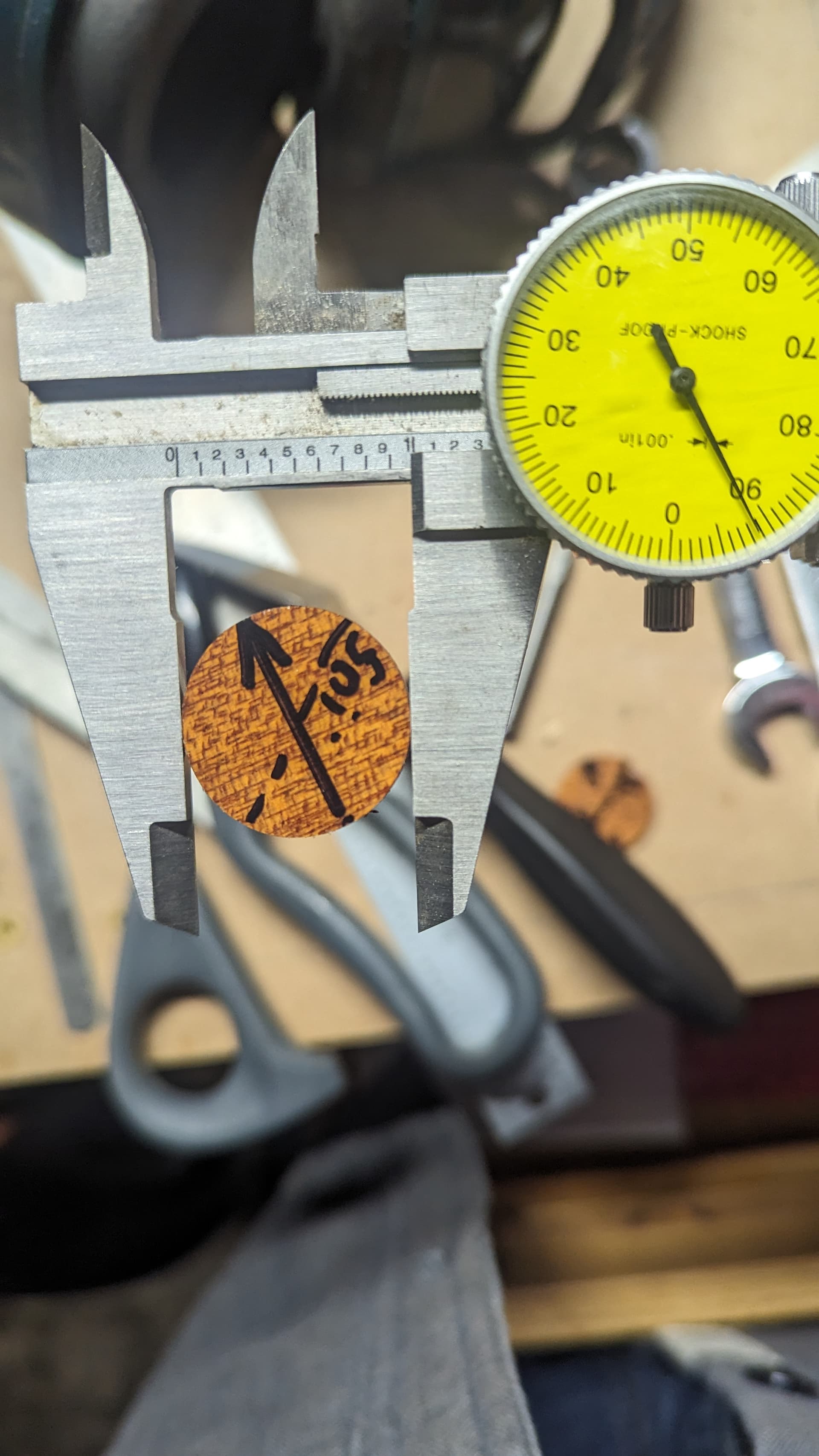
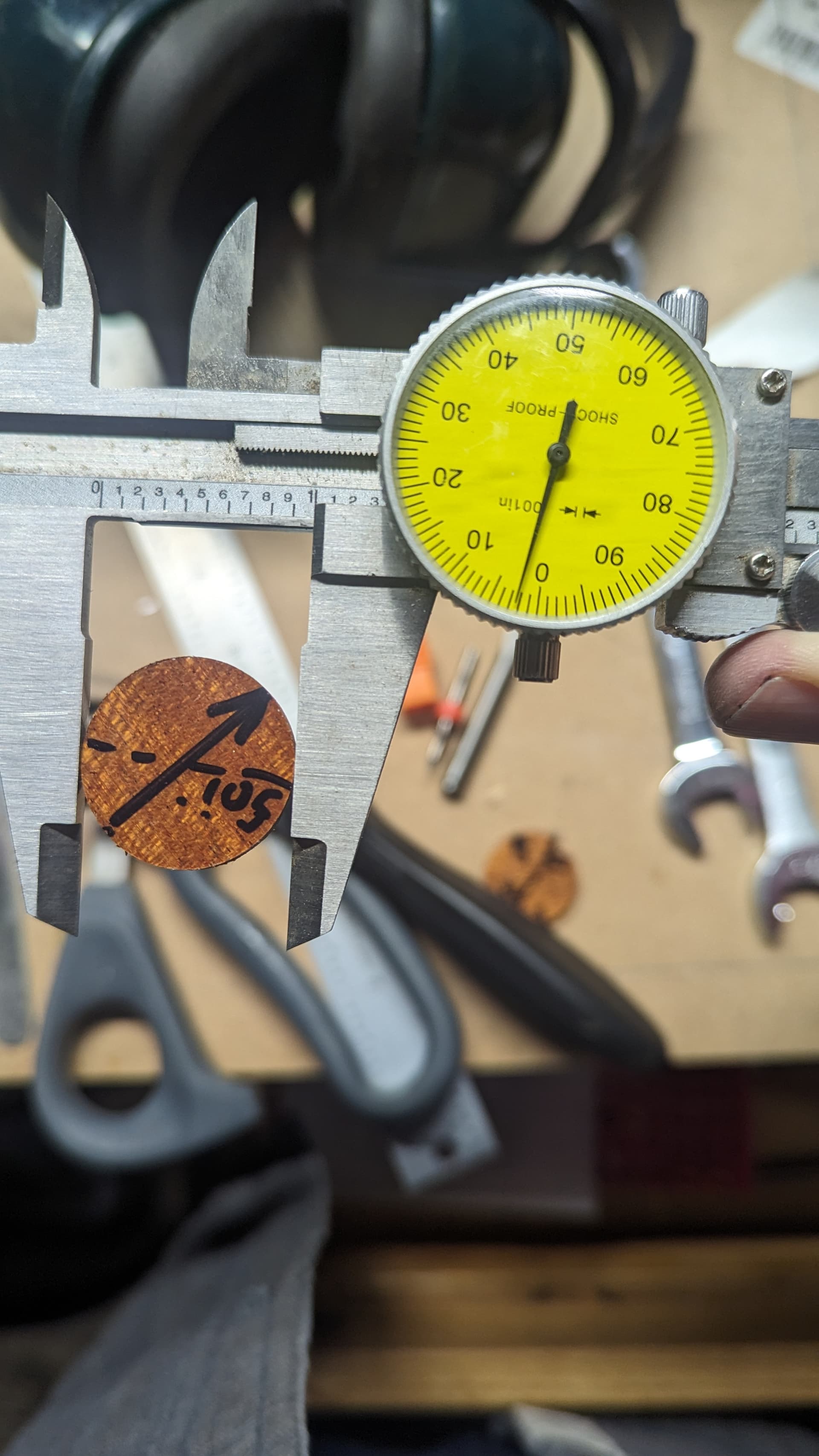
Arrow in pics on circle is Y North.
As you can see i’ve already done a BUNCH of testing. That is how I discovered my software workflow was flawed and learning about Geometric bounding box setting in Inkscape and redrawing designs and importing into ESTL and verifying with ruler. So I now know its not the software. Except my parts are smaller than intended so I don’t really know its not software but its not likely software. I am way over thinking now…
Thanks all
