I am starting a MPCNC primo build. It is pretty standard, so I am not planning on documenting extensively here, but will share progress and likely ask a lot of questions. Looking forward to having good discussions with the group here.
Build details:
Build area ~18x24"
Control: bought an SKR Pro with TFT display kit from V1E
Dual endstop
Makita router
Plan to add a laser at some point down the road
Table: I don’t have a permanent place for it right now, so I am building a 30x36" torsion box that I can hopefully move around.
Printed parts: I have printed most of the parts. I have two printers: a highly modified ender 3 with 0.6mm nozzle and a Flashforge creator 2 (Dual extrusion) with 0.4mm nozzle.
Build progress: most of the parts are in, most of the parts are printed. I have cut the pieces out for the torsion box and plan to assemble it this weekend, and hopefully start building the MPCNC.
I had a question on the torsion box: I am skinning it with 1/2" MDF. I think I need to have some plywood for the feet to bite into and I am not sure that I understand the Z travel. Would it work if I put 3/4" plywood pads under the feet, or would that make it difficult/impossible for the tool to reach the surface of the spoilboard? Essentially, the spoil board surface would be at the same height as the bottom of the feet.
My 24"x24" primo is mounted directly to 3/4" MDF and I had no problem with it biting in. I used pocket screws to mount the feet. they have a nice flat flange on them and I had them on hand lol. I don’t see why you would need the additional plywood under the feet. I think you’ll be just fine mounting it straight to the MDF
Hey stafford, welcome. I happen to be in Portland, and your build sounds quite a bit like mine - from the dimensions and on down to the 1/2" MDF with a sort of “standalone” torsion box/plate that I clamp to my workbench in the garage. The system works fine, and is relatively portable, the one drawback being that I did spend a considerable time designing, milling, and assembling a standalone box for the controls.
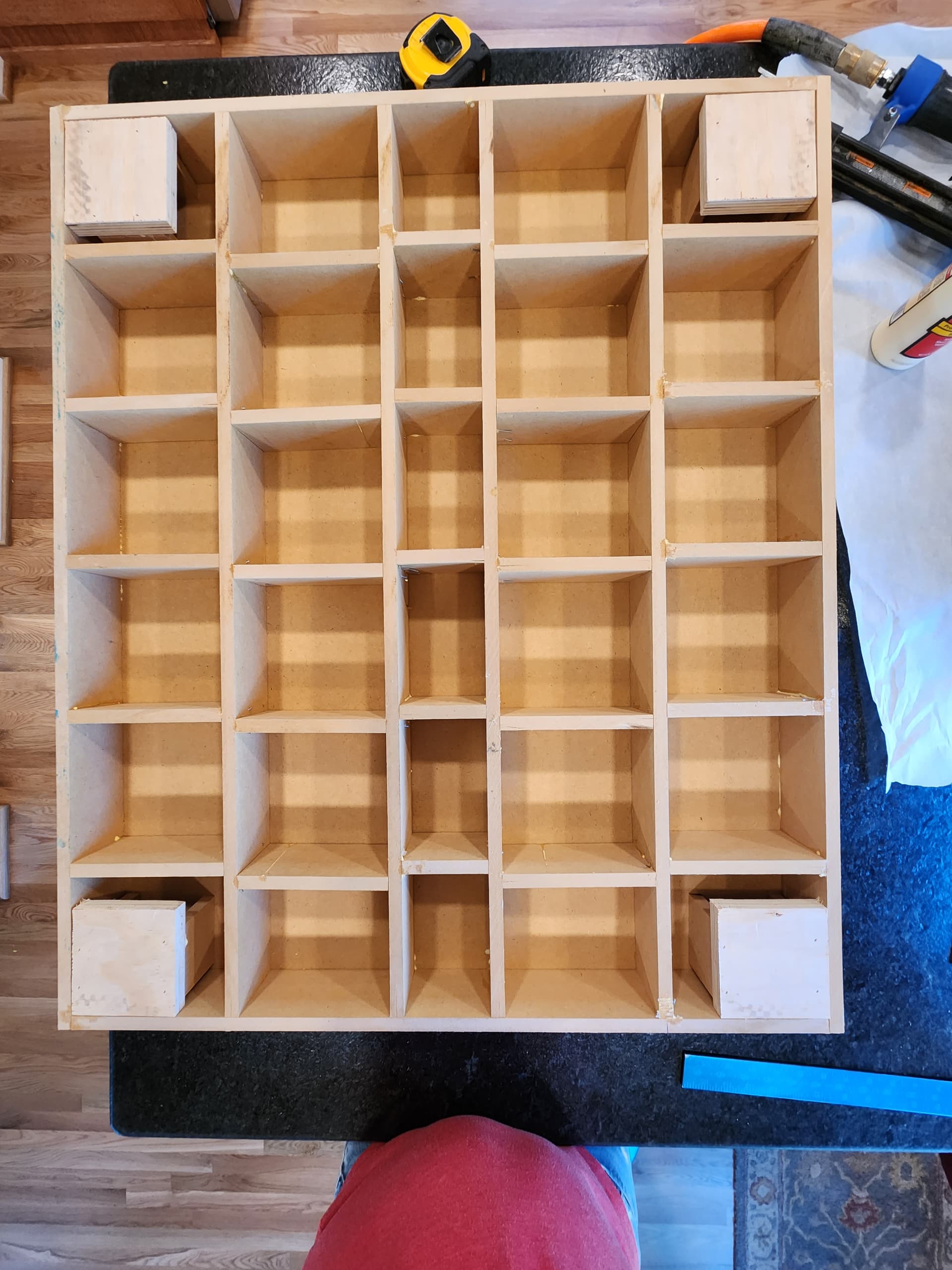
Re. your question about the torsion box; I made mine using strips of 1/2" plywood which I laminated together to create 1" thick strips, and cut them about 1" tall. Then sandwiched between 1/2" MDF sheets; total is something like 30" by 36". Then I added MDF strips on the sides of the top face to be able to fix the feet to and left a space in the middle for another MDF layer that could be swapped out (spoil board). This isn’t the most dynamic system or well-engineered system, but I was interested in making chips and, well, it works great for my purposes. Happy to go take some pics if that would help you.
I didn’t have any issue with the feet being well attached into the MDF. I used some basic 1" wood screws and they bit just fine. If you’re worried about that, I’d say you could consider the following:
Mark locations for holes for foot mounts
Use 6mm bit to bore out hole
Add glue to a 1/4" dowel, insert into the 6mm hole.
Let dry, cut flush
Drill feet into that.
But again, I haven’t had any issues and probably have 100+ hours milling now and have moved the whole machine several times. It’s very solid.
Thanks for the info. I ended up adding some 3/4" plywood under the mdf on the corners just in case. Build is coming along. I have the feet set, but realized I miss printing two bottom corners and two trucks. Ordering more pla and printing. I am really impressed by the tolerencing on the design. I am printing on two different printers, one with a 0.4mm nozzle and one with a 0.6mm nozzle. I have had to do very little post-processing to get things to fit.
Since I am building on a somewhat portable box, I am planning to use connectors on my control box so it can be separated from the box. At some point I may need to build something custom, but we will see.
Looks great, nice work, yours is gonna end up very sturdy indeed. For what it’s worth, my regret in rushing the build of the base isn’t one of strength but rather flatness. depending on whether you are going to surface your spoilboard and the kind of workholding you plan on, this may not be an issue, but figured I’d mention it can be a bit finnicky to get both surfaces of a torsion box totally flat, though I’m just admittedly not so meticulous with woodworking (milling is way more fun imo)
Another tip- print/cut/find a small “spacer” you can use to offset the feet in from the corners. I made sure my box was dead square on the diagonals, and when I installed the feet i just used an L-shaped plastic block to space the feet in from the corners evenly, and that made my build totally square from the start. Same goes if you use dual endstops, use a spacer to get them exactly the same distance from the corners. I haven’t experienced any of the accuracy issues others have mentioned, my rig has been nearly dead-on from the start due to the extra time taken to make sure my rails and endstops were as square as possible.
Thanks for the tips. My table was not perfectly square, but I was able to get the base as close as I can measure with a tape measure. I will definitely take my time with the end stops.
Wire management questions:
I see a lot of builds with drag chains and some with the mesh conduit. Preference here? If you are using drag chains, did you print them or buy them (links would be appreciated)?
I started with drag chains, and they were a bit of a challenge to string all the wiring through. I have bought them from Amazon and they were NOT the ones with a clip on top, which allows installing the wiring after routing the chains.
I later changed it to the Tape Measure trick which I found easier to install and required less added parts to the build.
I’ve been happy with that solution, but again you need to thread all the wires through at the first.
Drag chains seemed spendy to me relative to the other parts, and the 3D printed ones always kinda seemed shitty - I have them on my 3D printers and they don’t really flow, they just kinda scrape along (not to mention would take forever to print a full batch).
I sleeved stepper wires and endstop wires separately and I designed some 3D printed clips mounted to the side of my torsion box to keep them situated all nice, that’s been plenty.
I reason that if wires wear or fail or disconnect it’s an annoying but inexpensive fix, and realistically you’d probably crack a printed part or loose up a bolt or have a bunch of other problems before you’d ever have to worry about a wire flexing too many times to failure…
For a portable system you definitely want a detachable control box though. I used aviation plugs like these:
I picked up a pack of 4 pin (steppers) and 2 pin (stops).
They’re a bit annoying to solder (definitely pre-tin the conductors) but I couldn’t really find a suitable alternative in the same price range. They won’t mount to anything over about 1/4" thick so I ended up printing some “plates” to mount them to for my milled control box.
Good progress so far. I have it all built and wired. I have been able to move all the axis in the correct directions using the LCD. I tested all the end stops and correct a swapped one. I homed the x-axis and it worked as expected. I tried to home the y-axis and it started to move towards home and then started shuttering. It works fine if I move it Y+ or Y- on the LCD, but when I try to home it does this. Any ideas?
Yes, i have end stops. It was initiated from the lcd. It worked fine on x, but shuddered on the y. It moves fine for the full range if I use the jog on the lcd.
If you can share what firmware the screen says we can also check if it is the correct one for your build.
A picture of your control board wired up is usually pretty helpful as well. You are having a uncommon issue so something is wrong, but we definitely need details to help get it sorted out.
Thanks for the help. It turns out it was a loose connection on the Y2 end stop. I was thinking about it wrong. I was thinking one may be shorted, but since they are normally closed an open connection looks like it is triggered. So one side triggered and the stepper stopped and the other side tried to keep going. I had tested them all and then put the lid on the box and did not retest. Something must have pulled on it when I reassembled.