I feel like I’m going crazy… Everyone with this plug seems to have 4 prongs in the switch part… The only place I could find with someone using 3 pronged one, he skips the 3rd!
I just need some help with how exactly I need to wire this plug…
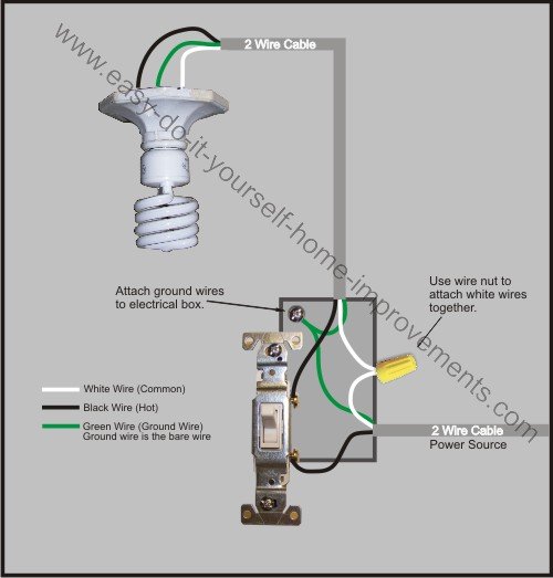
Assuming standard color conventions, i.e., black is hot (line), white is neutral, and green is ground, here’s what you’d do:
Check continuity of the terminals (input to output) with the switch in the energized/on position to figure out which input terminal is connected to which output terminal.
the switch has two states off and on. When it is off then the center terminal is connected to the other prong on the switch. it is a Single Pole Double Throw (SPDT).
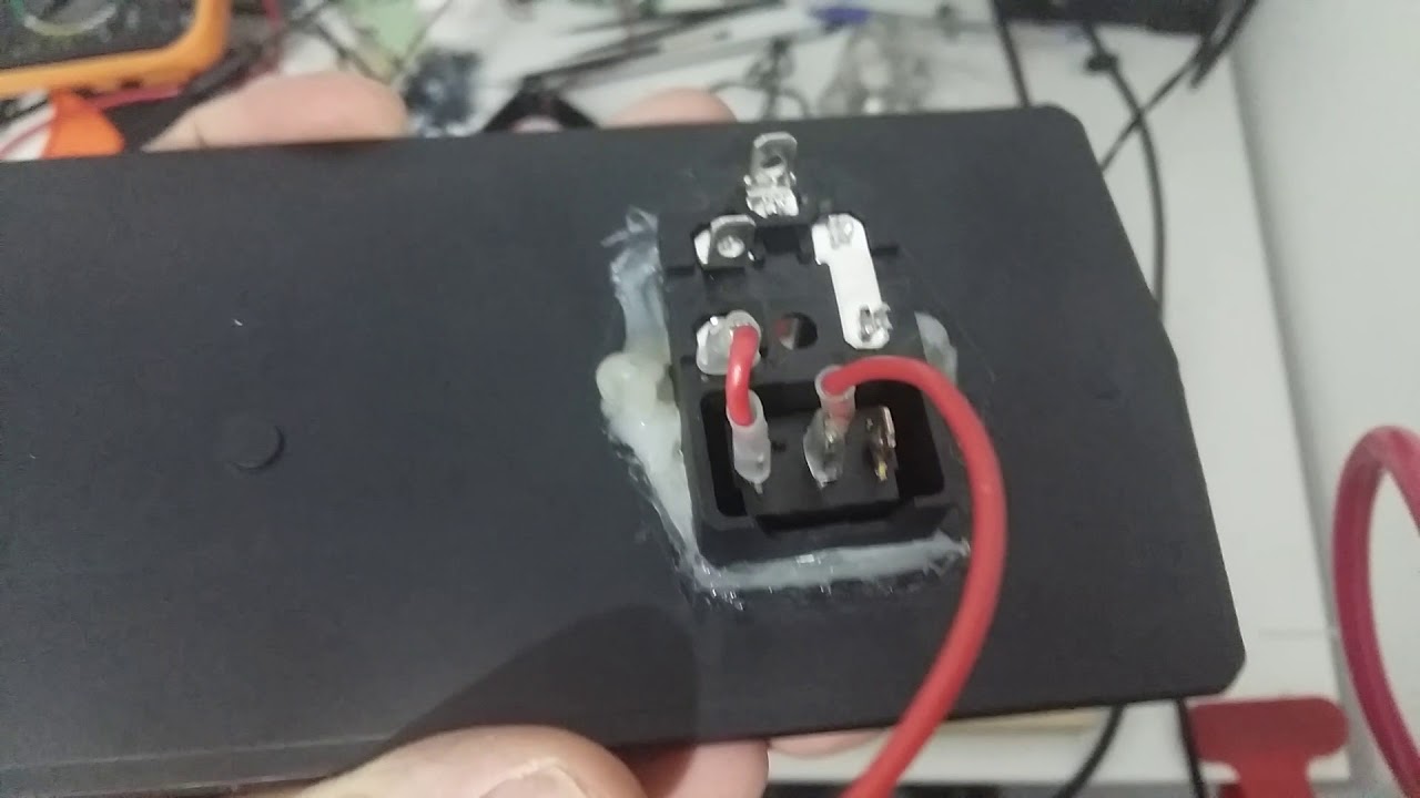
It is my humble opinion that the wiring above (2 red wires) is incorrect. The jumper from the load out from the fuse should go to the center position on the switch. If you want the switch to light when powered the bronze terminal (3) should be connected to Neutral (Not ground). I have attached to photos to back up my opinion.You must look close to see the numbers on the switch photo.
[attachment file=“Screen Shot 2019-02-11 at 3.37.38 PM.png”]
[attachment file=“Screen Shot 2019-02-11 at 3.36.50 PM.png”]
Just a FYI, you need to connect the neutral to the power supply too. Also the light turns on with power even it you swap the red wires at the switch, I was looking at resoldering the thing when I just tried it and it worked. Love the fuse.
So, after a couple of months, had a bit of drama with this, was cutting something and everything died on me. Bit of an oh shit! moment, but turns out the fuse was OK, but the connection on the far end of the fuse to the wires was the problem. So, good news, I can still use the fuse, but can’t use the switch. Will have to go with something beefier methinks, no doubt user error, but it probably needs a smaller fuse. The rest of the stuff works fine, rasp pi, mini rambo, steppers, etc, and the fuse, my favourite part.
Cheers!
EDIT:
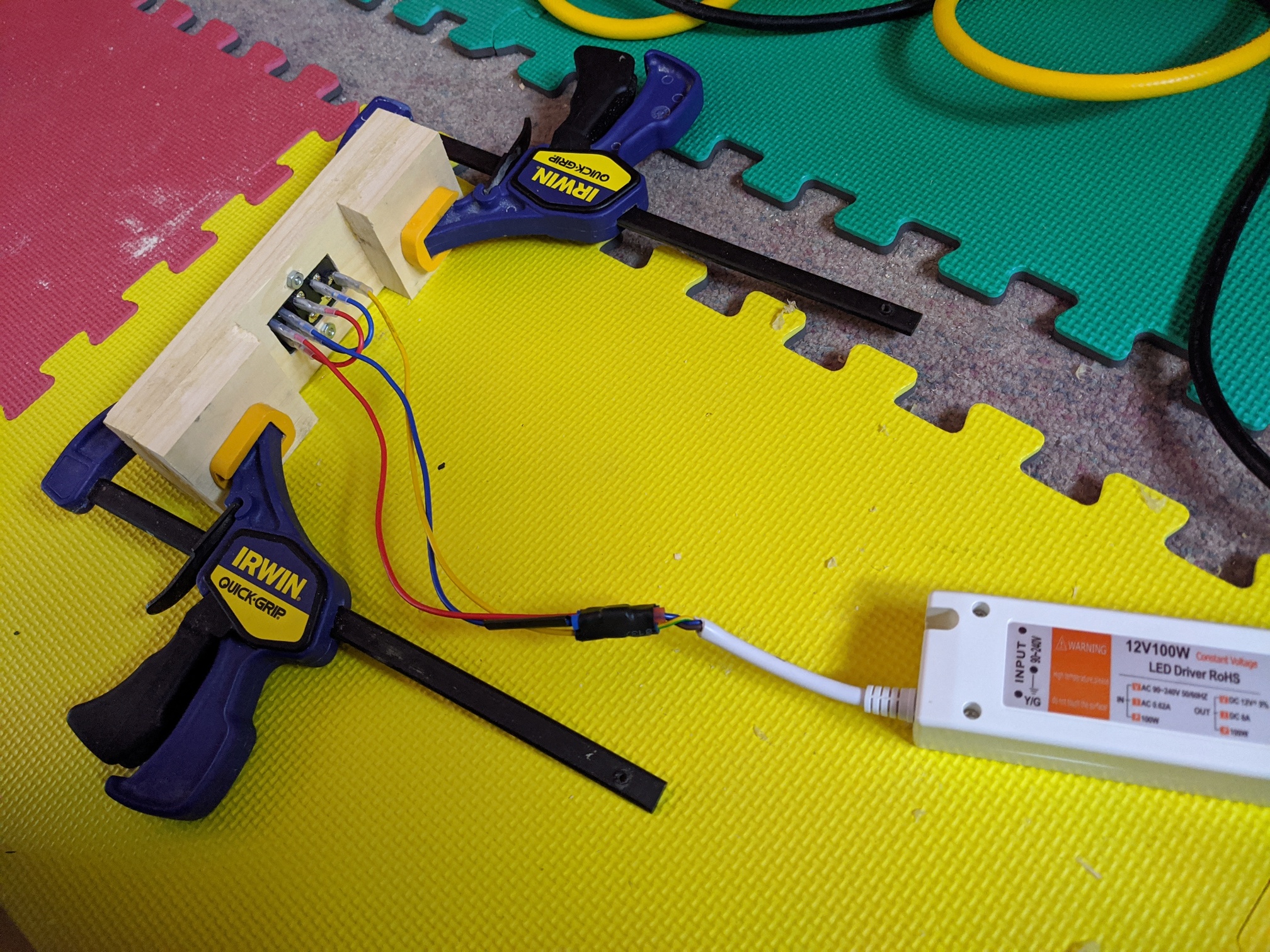
Bought another one with the wires done already, so follow the order in the pic.


 Also the light turns on with power even it you swap the red wires at the switch, I was looking at resoldering the thing when I just tried it and it worked. Love the fuse.