Planning out enclosure and wiring - gut check on plan

Working on wiring up my new Jackpot board for existing Primo build. I’m pretty comfortable with where the steppers will plug in, and while I have a little learning curve left on the endstop wiring, I’m not too concerned about that.

Where I’d like opinions is on my plan for the mains voltage (120v US) and controlling router power.

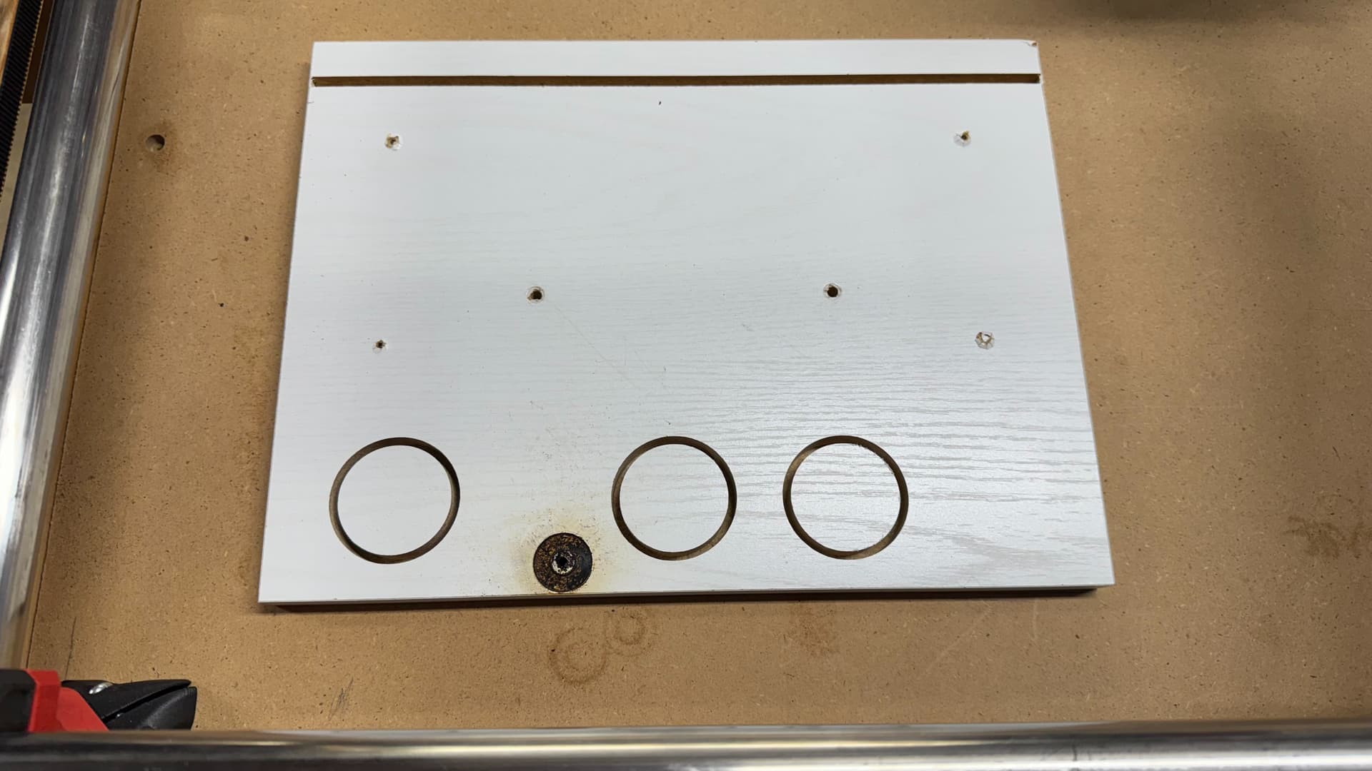
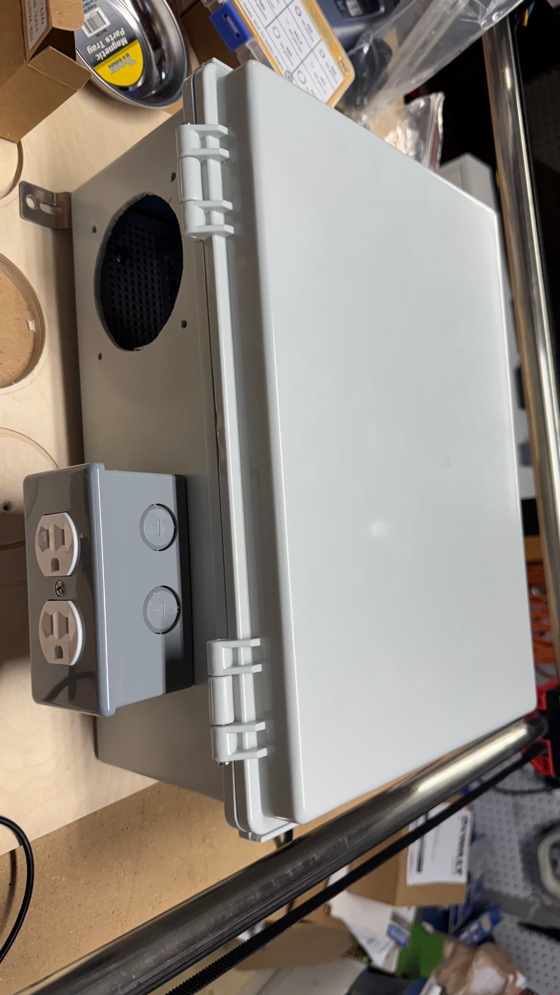
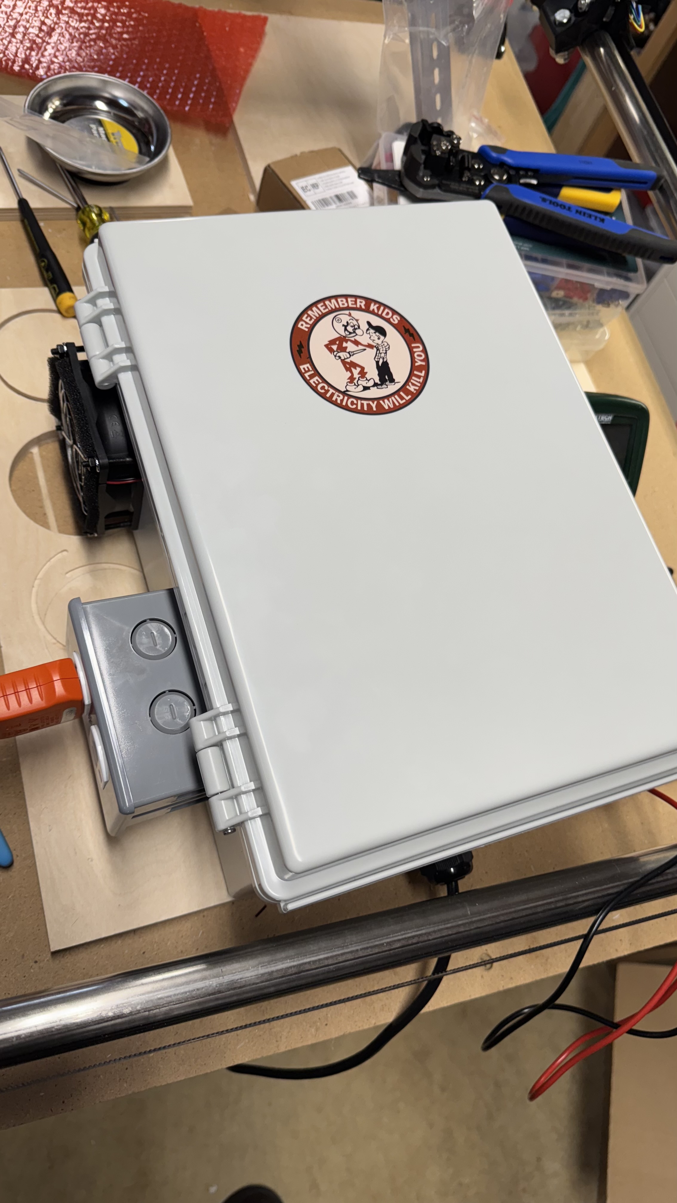
I’m housing everything in an outdoor box I bought for Christmas light projects that didn’t materialize this year, since the box has a nice grid for mounting, and plenty of room.

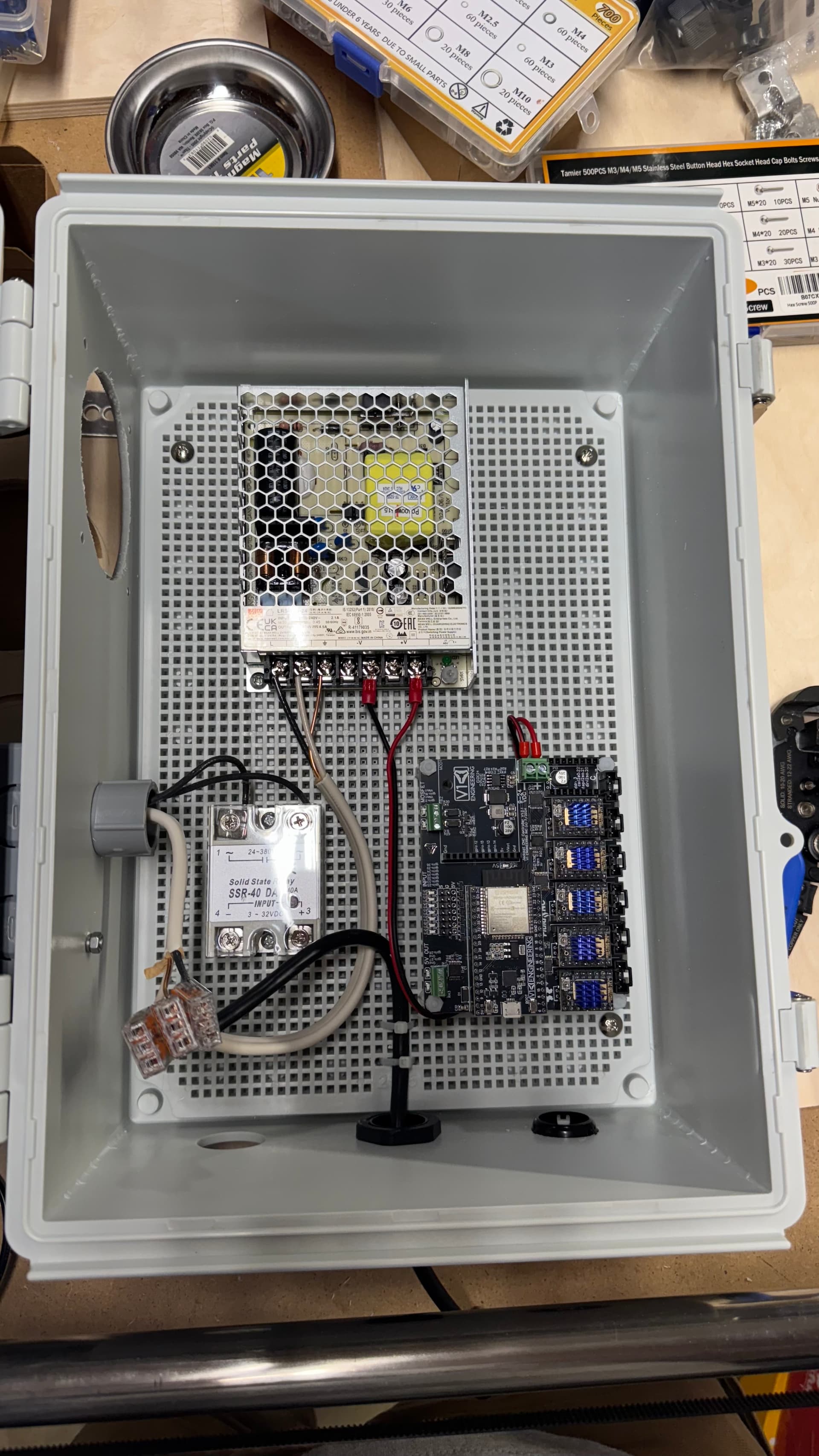
I’m powering the Jackpot and any other 24V stuff with a Meanwell 4.5A PSU (overkill, but I know it’ll be solid), and I have an SSR for allowing switching of the Makita router I’m using via a pin on the Jackpot.

I originally got an emergency stop button that would require wiring, but after reading some threads here, decided to order a Rockler router table switch with a paddle for the stop, and just plug the main power for the enclosure into that. Much simpler for wiring, and if I need to stop everything, it all goes, period.

My plan is to bring the AC cable (a cut-off PC power cable) into the enclosure, and terminate each wire with a WAGO 221 lever nut. One of the remaining 3 terminals on each WAGO would go to the Meanwell PSU, while the last terminal on each would be dedicated to a receptacle for the router, which would mount on the side of the box, allowing me to avoid butchering the router cord. The hot line of that would go through the high-voltage side of the SSR, with the LV side of the SSR wired up to a pin on the Jackpot, which I could then set up with either a macro, or control via gcode to turn the router on or off.

Also planning to have at least one 24v cooling fan in the enclosure, wired to the Meanwell PSU and drawing air from the bottom of the case (to minimize dust, though I might also add a filter) and exhausting it out the side .

If I wanted to be really safety conscious, I could put a kill switch on the door to the enclosure so that nothing inside can be energized with the door open, but I think I will likely be fine with the external paddle switch, or just unplugging it if I need to get inside. Might zip tie the door just as a reminder to cut power and zip tie at the same time. :smiley:

Does all that seem like a fairly sensible plan?

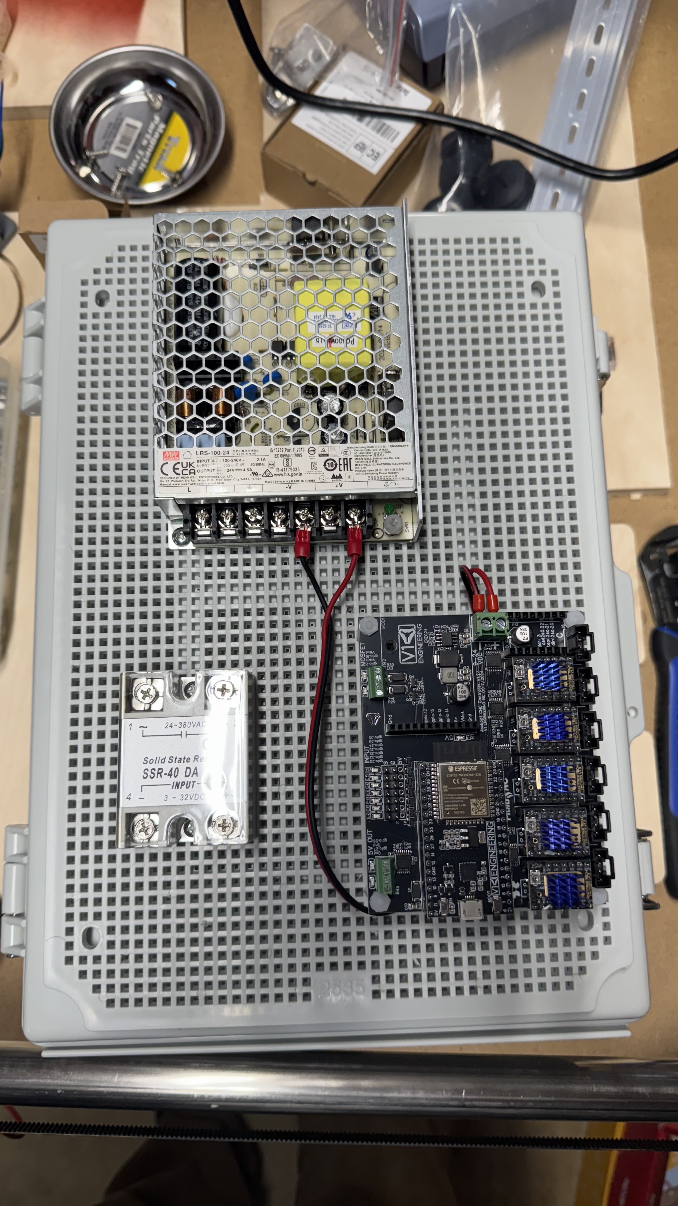
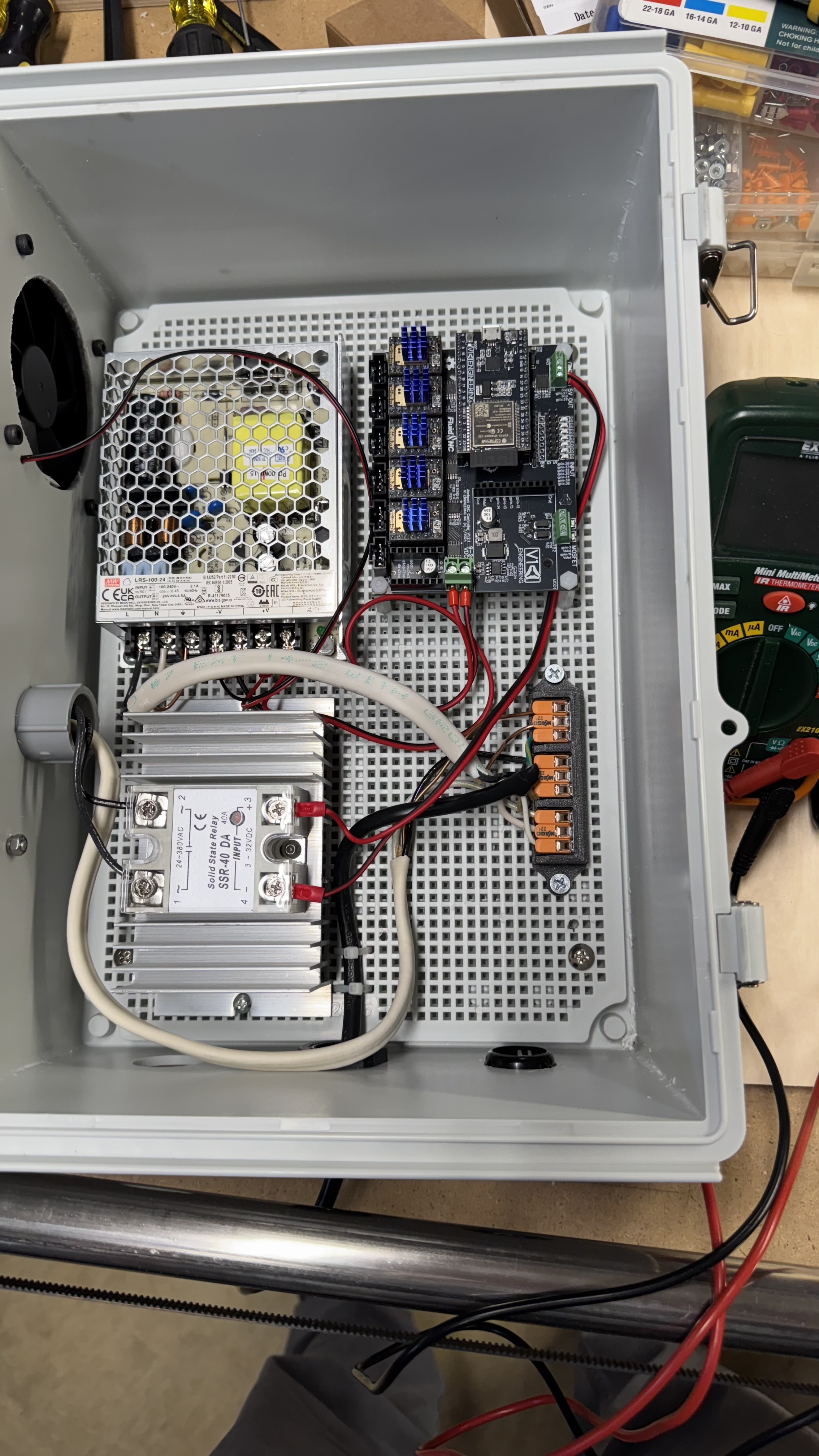
I’ll post some pictures once I start getting things more fully wired up. I already have the PSU mounted and did a quick test wiring and boot of the Jackpot just to test it after it arrived in a rather beat-up box (thanks, USPS!), and all was well at that point.

Adding an initial pic…this mounting plate screws to the back of the enclosure. Cooling fan will mount to the left of the PSU, and I’ll mount a receptacle to either the upper right, or lower left. More pics to come…

You probably need a cord cover, a lock-out tag-out lock, hasp, and tag and a written procedure for testing to go with it if you really wanted to be osha compliant. But yeah it sounds good otherwise.

1 Like

LOL…thankfully, I’m not in that kind of environment…mostly I have to protect against my own stupidity, rather than that of others. I will still almost certainly make sure all mains-level terminals have appropriate covers or enclosures even inside the box, and add a warning sticker on the box door (maybe Reddy Killowatt ?).

While I avoid working live on anything over 24v or so, it does not hurt to have extra protection from absent-mindedness or someone in the household being unexpectedly curious (thankfully, my sons are both adults, so they’re a lot less likely to be poking their noses into a box with wires than youngers would be).

With the SSR, all you have to do is kill the power to the control board to stop the router. It is a tiny bit safer to have the emergency stop on the AC, but having it on the DC side might allow for easier placement of the emergency switch. That is, you can use smaller wire, and it is easier if you want multiple switches.

@robertbu That was actually my original plan when I bought all my gear, but the wiring for that would be mildly more complicated, and doesn’t gain much.

Plus, the size and shape of the emergency stop button I originally bought (this one) would have made for more awkward mounting, and likely been harder to use.

With the Rockler switch, the paddle makes it easy to shut everything off in an emergency, even using my knee, if my hands aren’t free. And that allows me to use the SSR solely as a controller for the router/spindle via software or gcode.

The other thing to consider with respect to using the SSR as the source for the emergency stop is that you would want the e-stop switch to break the hot connection on the low-voltage side, not rely on cutting power to the board. Unfortunately, I’ve had recent experience with boards failing in such a way that power is continuously supplied, so I’m very leery of relying on anything indirect for safety. One big physical switch is a more reliable shutoff.

2 Likes

I’m still finishing my MPCNC and like your idea. I don’t like cutting cords for tools like a router, in order to wire in an e stop properly. So even though it’s $20-30 on amazon, I think it’s worth it to keep the usability of a not so cheap tool. Plus the fact it is HUGE is a plus.

The Rockler switch was $40 for me on Amazon, but if you have a local Rockler store in your area, it was on sale on Rockler.com for $30. I don’t have time at the moment to get to my local store, so I just sucked it up and paid the extra on Amazon, because shipping from Rockler would have eaten up the savings anyway.

Probably should’ve checked my local Woodcraft store, which is 10 minutes from my house, to see if they had something similar.

Keep in mind that even if you wanted to wire in your own e-stop, you could do that without cutting the router cord by wiring up a receptacle like I’m planning to do. It would just be slightly different wiring. Lots of different ways to approach this.

2 Likes

On my original MPCNC (Burly), I wired the estop switch into the cord to a power strip, and the power supply and the router plugged into the strip. When I upgraded to the Primo, I moved to an IOT relay and placed the stop on the DC side. This allowed me to easily wire up two wired stop switches plus a wireless one. I acknowledge there is a bit of risk in my DC setup. For example, the IOT relay could fail to turn off when the signal is lost.

1 Like

Yep. And to be clear, wasn’t criticizing. Different levels of risk tolerance call for different solutions.

As an avid Home Assistant user, there’s part of me that wants to use HA to control all the things. But having already managed to crash my endmill all the way into a piece of particle board by loading the wrong gcode, I’m less concerned in this case about scratching my automation itch, and more concerned about immediately stopping the imminent fire. :smiley: :fire:

I’ve had similar kinds of crashes. My CNC is on my back patio. I positioned it against the non-moving side of a sliding glass door so I can watch CNC from inside the house, where it is warmer, quieter, and in the case of my laser, out of the smoke. I wanted a wireless solution, so I could immediately kill the CNC without having to stand up and open the door, so doing the wiring on the DC side made sense to me.

I know there are decent wireless AC solutions. For a very brief moment I considered using my Echo, but…

“Alexa, turn off the CNC”

  • “Sorry, I cannot connect to the internet.”
  • “Sorry, I don’t know CMD.”
  • “Sorry, the CNC is not responding.”
2 Likes

Yup. I have a Kasa 3-plug power strip that my 3D printers are plugged into. So if a print is going south and for whatever reason cancelling via Prusa’s web interface doesn’t work, I can kill the power remotely.

But in the case of my MK4, at least, I’m much less worried about its potential to fail catastrophically than I am my Primo, so my comfort level with remote control and printing unattended is higher.

I think given what you described about your setup, your solution makes sense to me.

Making progress. Wired up the line input to the PSU and relay and receptacle. Decided to splurge and got the Leviton lever receptacle…SO easy to install. Receptacle is mounted outside the main enclosure, for additional safety, though with the lever wiring on the receptacle, there’s no exposed terminals anyway.

Still need to wire up the low-voltage side of the SSR, but I wanted to make sure I do that right so I don’t screw something up on the board. From what I’ve gathered, it looks like the 5V capable GPIOs to the left of the endstop pins is the right place to wire up the SSR.

[EDIT]: Turns out that the default firmware already has macros wired up for GPIO 26 and 27, so this is much easier than I was expecting. I need to check the underlying gcode for the macros so I know how to turn the tool on as part of a job, but I wired it all up and it’s working perfectly.

Also found this thread that indicates that I could also use the MOSFET terminals, with a helpful video by @Nathan_Doty (Thanks!). I think I’m going to try with the 5v terminals first, however.

Pics:

Fan (24V) will get wired to the spare terminals on the PSU, but I’m waiting on longer bolts to mount that.

One last thing…I see from this post (and saw on the video mentioned above) that some folks use a heatsink on the SSR…should I be planning around that? Currently, the SSR is just mounted to the plastic mounting board. Would rather not melt that, or risk a fire.

Looks like the commands for the 2 5V GPIO pins are:

M62 P0 # Turn on GPIO 26
M63 P0 # Turn off GPIO 26

M62 P1 # Turn on GPIO 27
M63 P1 # Turn off GPIO 27

Sent those from the console in the web GUI, and it works great for both pins.

Also went ahead and ordered a heat sink for the SSR. Worst case, it’s overkill, but since this is all going to be in a closed box, more cooling is usually better.

1 Like

So I’ve finally gotten the wiring other than the steppers and endstops cleaned up, and added a heatsink for my SSR.

Unfortunately, it seems like my SSR may have failed at some point between when I last tested it, and presently, unless it was already failing and I just missed it somehow.

Essentially, when I turn on power at the external cutoff switch, power goes first to the WAGO connector block, and from there to the PSU and to the receptacle, with the hot line going through the high voltage side of the SSR. So without voltage on the LV side, no voltage should be present at the receptacle.

What is actually happening is that when I turn on power to the box, the PSU and Jackpot are powered normally, but I’m getting 85v at the receptacle. Not good.

I’ve tested with everything turned off, and I get no continuity across the HV terminals on the SSR, but as soon as I power things up, there’s only about 10 MOhm resistance, and 85v from the output of the SSR to either neutral or ground. This occurs even if I completely disconnect the LV side, so I am pretty sure it’s the SSR. With no voltage on the LV side, the LED on the SSR is dark, but still passes 85v. If I turn on the Jackpot pin that I set this up on, the LED comes on, and I get 120v at the receptacle.

Does this sound like a typical SSR failure (I know they fail open, but it’s weird to me that this one hasn’t really been stressed at all, and has failed without any external indication, no burning or melting or anything)?

Bonus pic of the outside of the box:

1 Like

My day job involves petrochemical plants. On those from a safety side when you’re looking at electrical boxes out in the field or elsewhere. You separate the stuff that can kill you from the stuff that can’t into different boxes wherever possible, which is 99.9% of the time.
If you can’t get it into a separate box, then there needs to be another barrier inside the box you’ve got to cross before you can get to the stuff that can kill you.

Look at the Swiss cheese model of safety, you don’t want to be one bad choice away from being dead.

I’ve seen lots of scary installs of mains voltage SSRs, I know you guys mostly only have 110V to play with, but still that’s going to do more than give a little tickle.

The 85 VAC may be a clue. That would be about the voltage of half a cycle. Perhaps a bad SSR. But first lets check the 5 v source. When turned on do you measure +5 volts? If not then you may be pulling more current driving the SSR than the Jackpot can handle ( about 25 ma). If it measures 5 v,next is to make sure it is not in PWM mode. Or a more simple test use a seperate supply or battery to test it.
Last test with some load. I have found a few of these SSR’s do not work without a load.

I don’t disagree at all. And I’m well aware of the risks, but there is no way to measure the voltage going to the PSU and coming across/from the SSR without having the terminals exposed.

Absolutely NONE of the work that I have done or will do in terms of connecting or disconnecting is while live. I’ve gotten bit by 120 before, and while it’s not as bad as what you probably work with, it’s no fun, and I know can be deadly. Before changing anything, the estop switch gets turned off, AND the box gets unplugged.

FWIW, the SSR has a clear cover, so aside from using a screwdriver or other metal implement, it is not easy to casually touch the terminals. Once the wiring is finished, I will also add a cover to the PSU terminals. So there will be no exposed 120v in the box.

I appreciate the cautions. Agree that it’s better to be safe than sorry.

When I power on the Jackpot, the terminal (GPIO26) is at 0V DC across the positive and negative for that GPIO. Once I go into Fluid Web UI and activate GPIO26, the terminals read +5V.

I’m using the default firmware shipped from V1, and I’m pretty sure that defaults to HIGH/LOW for GPIO 26 and 27.

I’ve tested with the SSR completely disconnected from the Jackpot, but not using a separate power source.

Thing is, I don’t have any issues with the AC voltage from the SSR when the low side is activated. If I turn on GPIO26, and it sends +5V, the SSR opens up and supplies the full 120V. The issue is when no voltage is applied on the low side. Even with nothing connected on that side at all, I still get 85VAC from the SSR.

I suppose I could plug a lamp or some other load in that would be unlikely to be damaged by lower voltage, but I’m definitely not risking my Makita router on that test, though I don’t think the risk is high.

I usually use a low walt lamp or heating element

Winner winner, chicken dinner!

Plugged a lamp with a 60w light bulb into the receptacle, and no voltage when the GPIO is low. Switch the GPIO on and the lamp comes on.

Tested with my router and it works great. Thank you for the tip on SSRs needing a load.

Now I’m wondering whether I should add in a load resistor, or just rely on the router to provide the load.

Also guess I don’t need the replacement SSR I ordered…but I’ll hold onto it as a backup, in case this one really does fail.