Interesting, how does that apply then, something to do with a difference between self sourcing from a lasercutter vs offering the service at cost?
You also can’t source Ryan’s plate from a cut service if you want to honour the license. You can cut them yourself or let a friend do it though if you don’t earn something with it. ![]()
CERN-OHL-W and Creative Commons Attribution-ShareAlike 4.0 International (CC BY-SA 4.0) seems to say it’s fine, it was only an idea for other UK makers that may not have access to their own alu capable CNC, not looking to retire to the Bahamas on it ![]()
Sorry, didn’t want to be anal about it. ![]() Glad you checked.
Glad you checked.
nah, no worries, good to check! happy to do anything required to support awesome projects like this ![]()
AFAIK, none of Cam’s stuff in NC.
Yup it’s not NC. Appreciate the sentiment and consideration for the project, though!
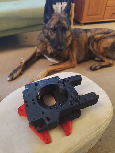
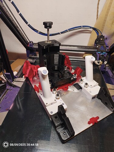
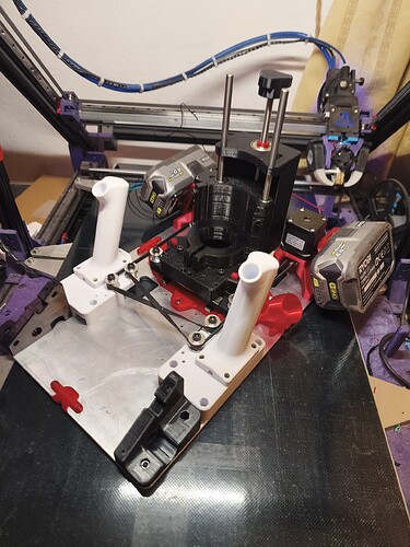
Also, the build is looking great!! I’m stoked to see it start to getting put together. The 3D printed locators are a nice touch.
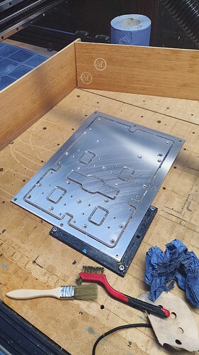
@Picklez Idk if you have already made the basePlate, but my supplier caught a mistake in the step file that the countersinks are not deep enough. I updated the design and pushed the new files to the repo
i’ll give my tool paths a check, the aluminium is due to arrive tomorrow so that’ll be this weekends job ![]()
My first batch of parts arrived, the aluminium has been delayed so doing what I can with what I have even if I have to undo it all again.
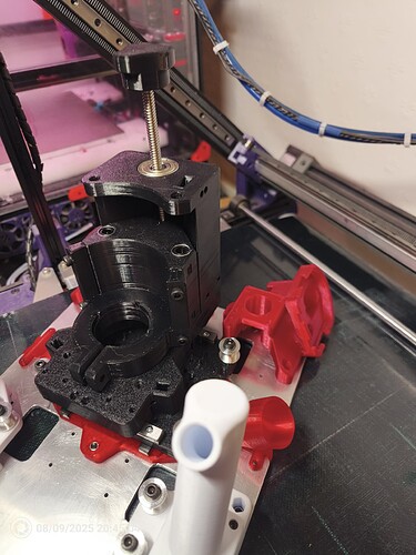
The tolerance on the smooth rod bearings was a little tight so need to reprint the carriage but everything else has been bang on, I’m enjoying myself ![]()
Beautiful!
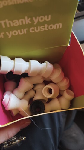
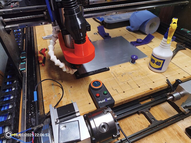
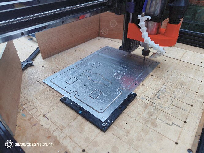
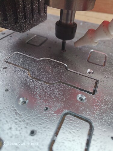
It took me far more iterations to get the loc-line style air duct dialled in and fitted than I’d care to admit, but now it’s ready to clear aluminium chips! Excited to get cutting the baseplate tomorrow afternoon:)
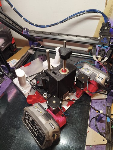
Nice rotary axis ![]()
That looks sweet, well done!
Build is going great!
I forgot to order the 16t pulleys and 10mm belt so minor delay there. Its gone together like a dream so far, quite enjoyed figuring it out from the cad model, like a puzzle!
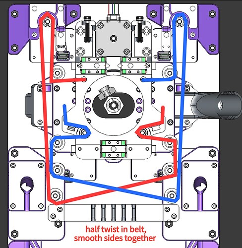
@camchaney any chance you could do a quick sketch of the belt path, that’s one bit I can’t devine ![]()
In the compass Webpage ist one Image showing the belt:
Make sure to pull the belt tight before installing the grooved slug to hold the tension. Start the belt run at the mounts near the top (need to be done before installing top axis plate), I formed a little loop with belt and pushed it into the hole, then insert M3 screw and the threads will grab the teeth.
You can actually feed the belt through the tensioner area with the slug after assembly using tweezers, so you don’t need to worry about guessing the direction of the twist in the belt while the whole thing is apart.
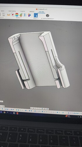
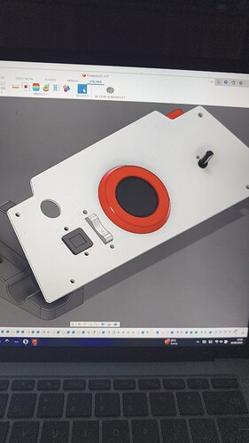
It’s really coming together now, need to toolpath the UI plate and wait for the PCBs to arrive. The battery mounts came out better than I hoped and the extra weight isn’t awful.
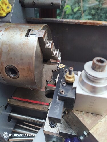
Had to fire up the lathe to shorten the tensioner pulleys (inspired design those!)
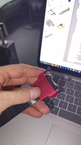
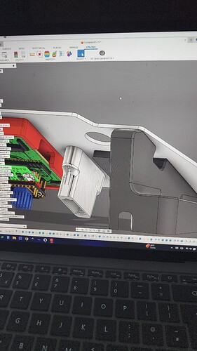
The panel mount for the SD extender was really fun. It has 2 little tabs that are pushed inwards to grip the plastic case when the screws are tightened, works a treat! Soldering and cable management next (some idiot cut wires off one of my spare stepper motors to extend another one).
Dude awesome!! So sorry I’m comig in so late, but you did a wonderful job on your own. I just finished up the build instructions, so you’re no longer wading in unknown waters:
Stoked you were able to get the belt path correct (thanks @matei ). If you ever need to route them again, though, there is an easier way hahah.
