Picked Up a Not Yet Working MPCNC From Craigslist - Need Advice on How Best to Setup

Today I picked up a mostly complete MPCNC from craigslist, and I’ll provide the description so folks can give me some pointers on what kind of work I’d need to do to get this up and running.

The Description

" This "Mostly Printed" CNC machine is currently configured as a "sharpie plotter," but has a functional 3d printer head and Dewalt DW660 router that are included. The MPCNC is a widely-used platform with a lot of community support and lots of adoption in the DIY community. Spare parts are printable with the machine itself, which is handy.

For more information, please visit https://www.v1e.com, the creators of the machine - this is a very flexible platform, and can be modified to have lots of other accessories (3d print heads, draw knives, laser cutters, plasma cutters, foam cutters...whatever you like!) However, as a diy-tier product, be prepared to sink some time into setup and calibration before you can use it. It's a great opportunity for someone looking to get their feet wet into CNC, but you'll need to know what you're doing if you want to get it running in a reasonable amount of time.

It's running off of a RAMPS 1.4 shield installed onto an Arduino Mega 2560 board. Control interface is a RepRap discount full-graphic smart controller, which allows you to insert an SD card with gcode and immediately start 3d printing or cutting without connecting a laptop. All power supplies needed are included.

Please note that this is NOT functional yet- it needs appropriate (free) Marlin firmware to be installed before it can be used. There are hundreds of dollars in parts here, and I have verified it works, but I am giving it away because I do not have the time to configure it, calibrate it, square it, etc."

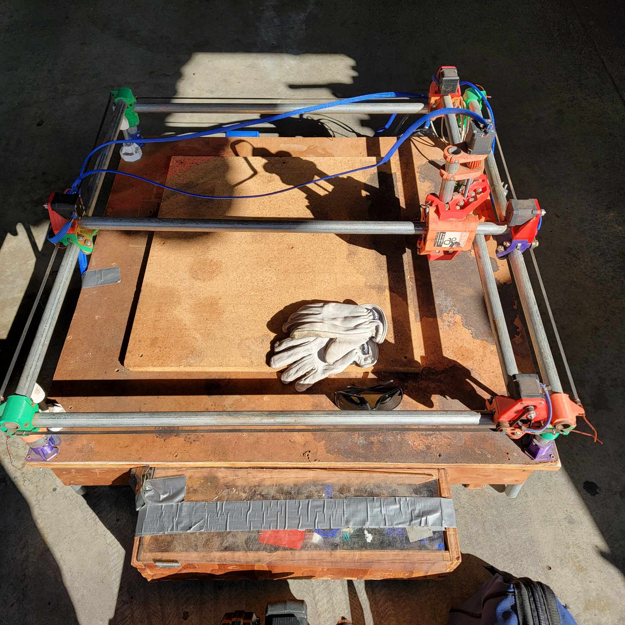
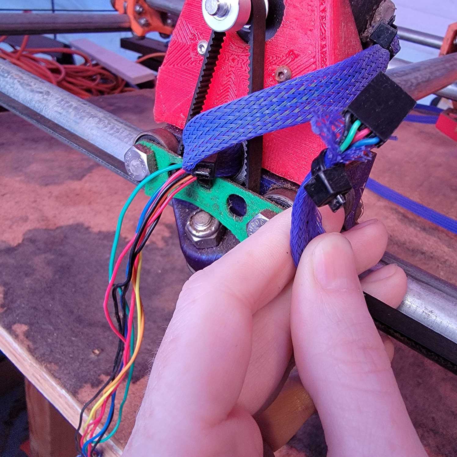
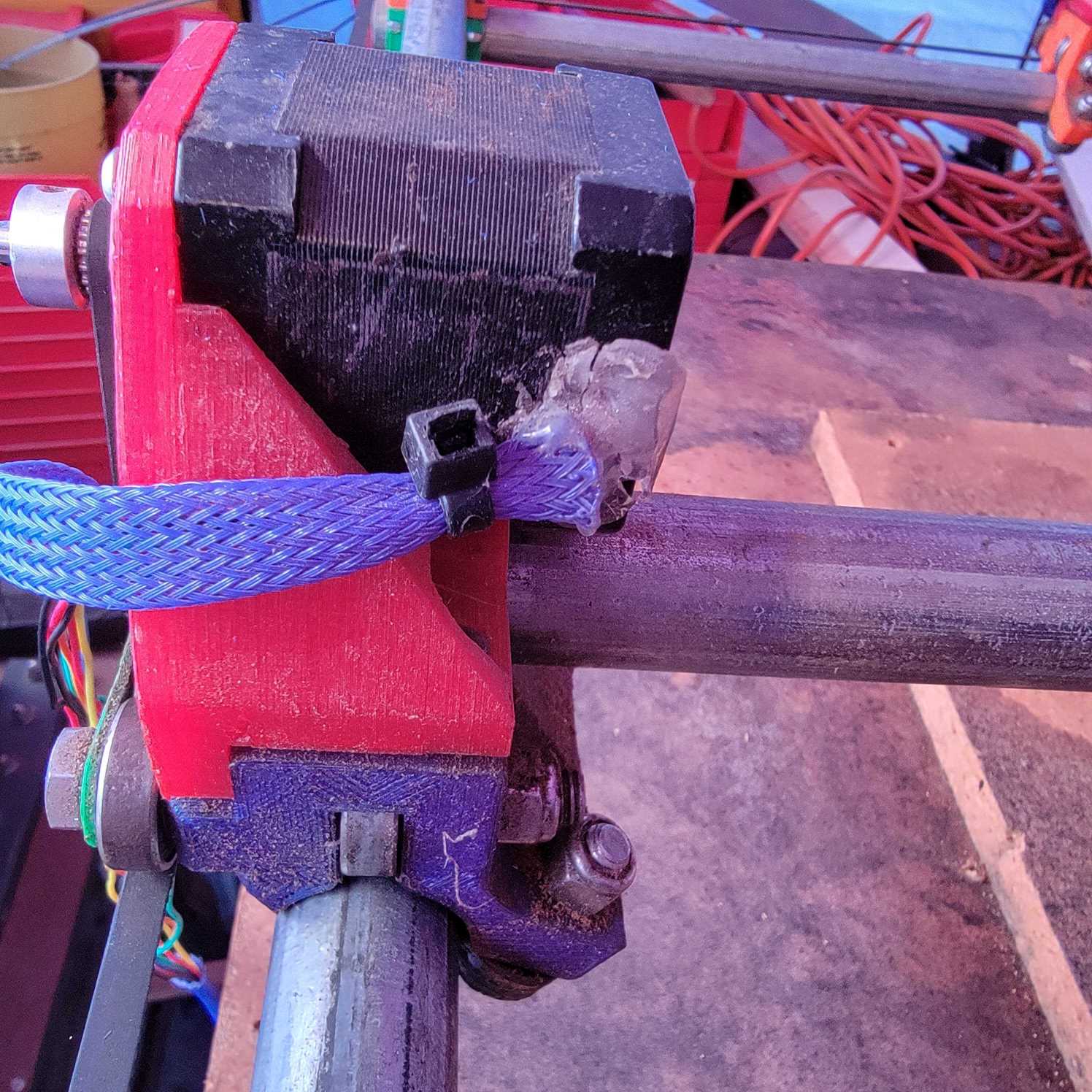
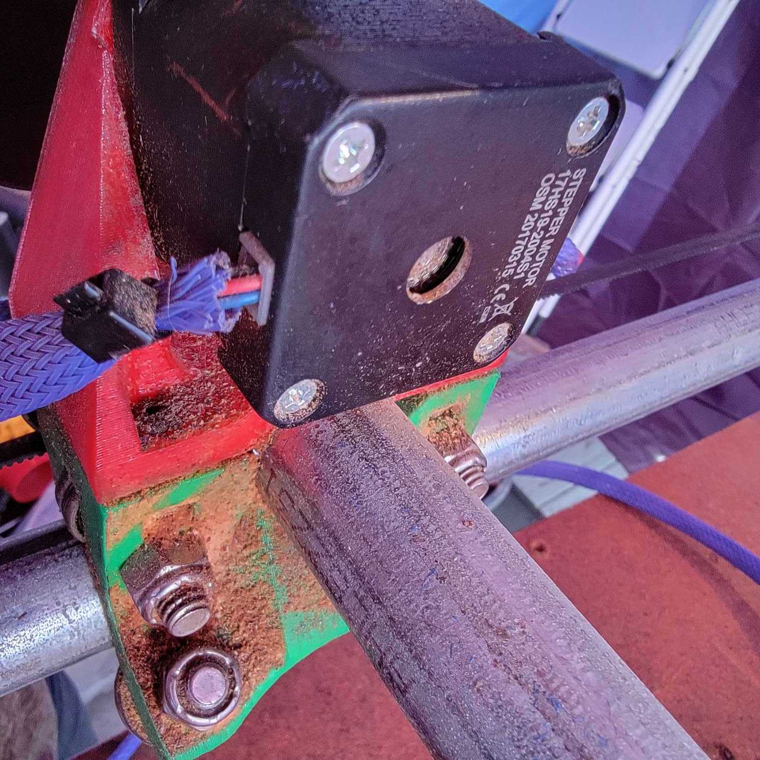
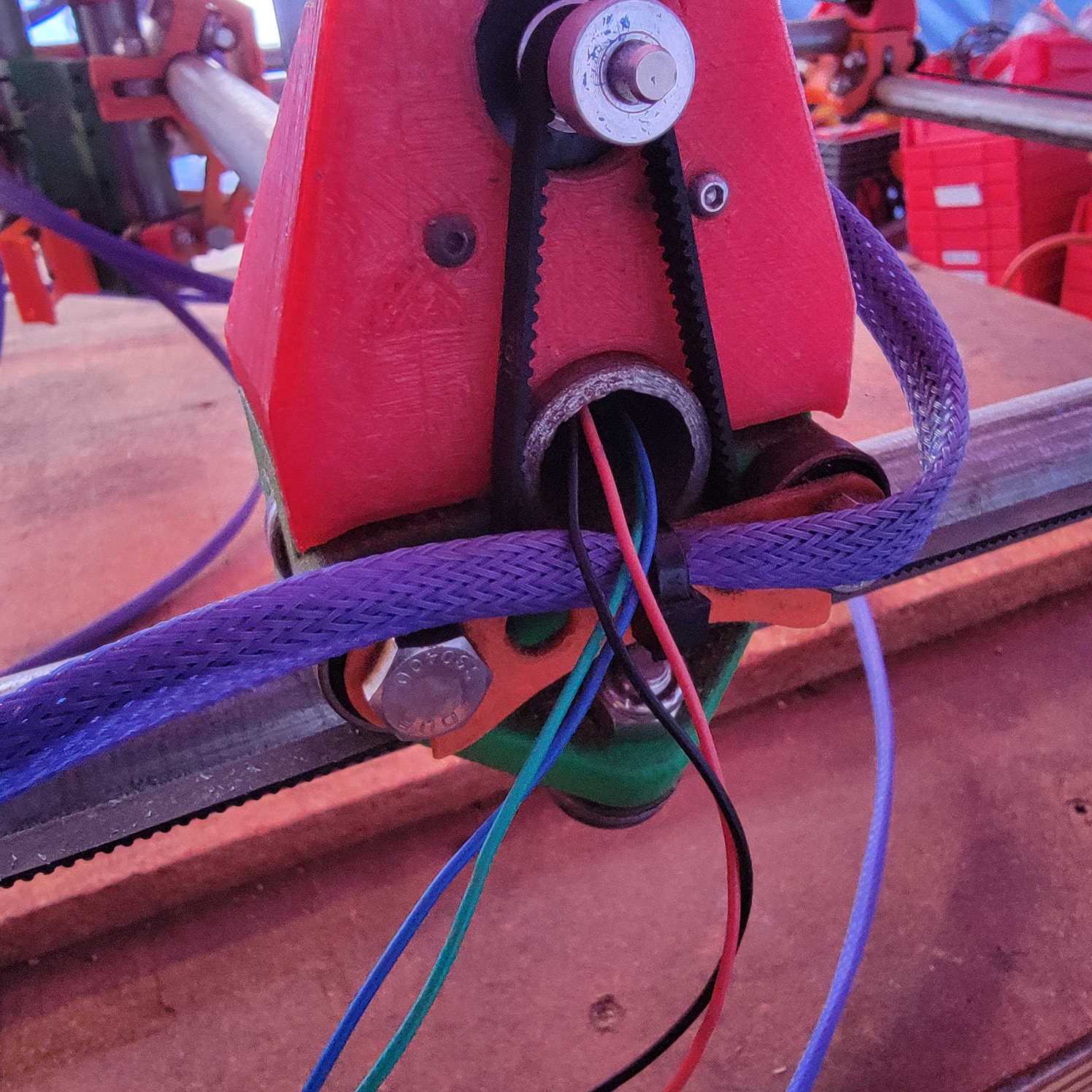
I haven’t put it back together again yet. I had to significantly dismantle it to get it into and onto my car. The electronics were kind of a mess and I plan on redoing all of this wiring and mounting anyway to protect them better.

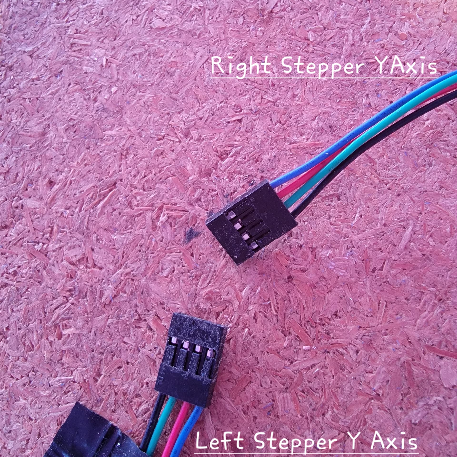
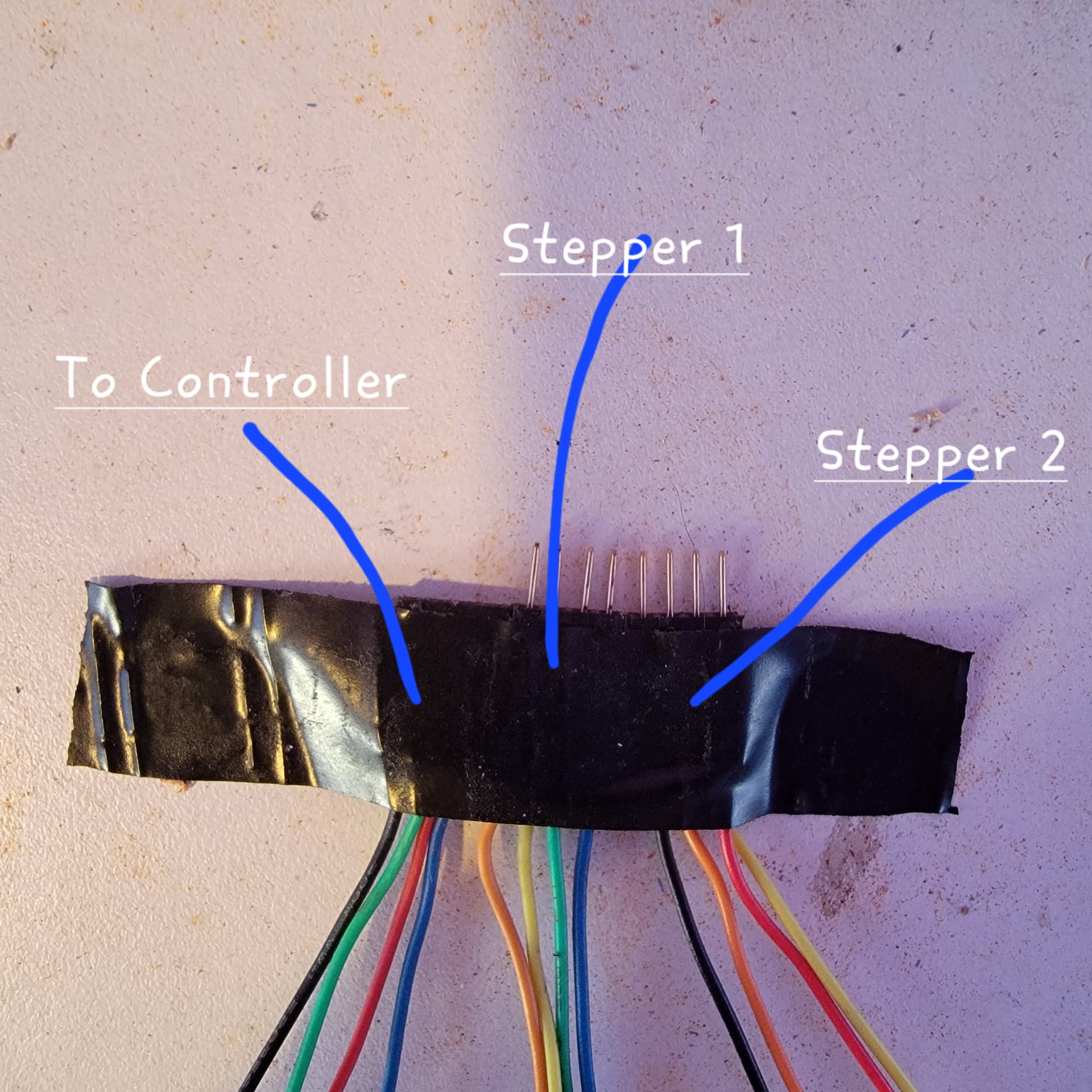
I’m going to include pictures I took of the setup before taking all of the electronics off and removing the CNC assembly from the base. I kept all of the motors attached to everything because I wasn’t sure how to put it back together after taking it apart.

Some Questions
1 - Should I tear it down and rebuild from scratch (all the pieces) or should I just put the CNC assembly back into the base?

2 - Are there any pieces I’m missing to be able to actually mount the router to the core? I’m assuming it’s fairly easy to get these printed by someone I know that has a 3D printer.

3 - The 3D printer head the unit came with looks super jank, but it might also still work since I can see some evidence of printing taking place with the unit itself. Should I spin up a different thread for this so I can provide pictures of the 3D printer head?

4 - The person I got it from made mention of setting up Marlin firmware into the unit. This shouldn’t be too much of a problem for me since I know how to do this sort of thing, but I’ve never used an Arduino before.

5 - Is this going to cost me a bunch of money to get back up and running again, or is this mostly just around patience of making sure I do the setup and calibration correctly?

Pictures

1 Like

I would provide more pictures but I’m unable to atm, I think I’ll upload them to imgur so folks can fully see what I’m dealing with.

I have an imgur link with images of the entire setup, but I can’t post it, assuming I’m too green atm.

You can “adjust” your posted link so that it does not read like a link from the computer and we can then reassemble it to see your pictures. After a short time on the forum, you will be allowed to most more pictues and post links. The limits are to reduce spam.

Pictures of the electronics would be helpful in giving you guidance. I’m sure we can help you get it working.

imgur com/gallery/3PdUSPR

The Ramps board is a combination of a Ramps 1.4 board and an Arduino Mega (usually clone) board. This setup works well for a MPCNC, but it is fragile. There is no protection on the pins, so it is relatively easy a to blow a pin or the voltage regulator on the Mega board. As you work with your electronics, always double check your connection and be careful to not short anything. Always power down the board before making any changes. On the plus side, if you do make a mistake, you can get a replacement Mega board off Amazon for under $20.

You will find the MPCNC/V1 firmware for this board here, and you want the one labeled V1CNC_Ramps. Inside the ZIP file, you will find a binary that can be burned to your board using XLoader. Alternately, you can use PlatformIO and compile the source (also in the ZIP file), and transfer it that way.

From your picture, you have four DRV8825 drivers on your Ramps board, but only three of them are in use. Since you have five stepper motors, it means that two pairs should be wired in series/serial. It would be good to check if this is how he wired the machine. If you don’t know the difference between series and parallel wiring, post back and we can provide some additional information.

The DRV8825 drivers need to have their VREF checked/set. The VREF sets the current limit for the driver. I used this tutorial the first time I set up a DRV8825, but you can find many tutorials on the subject including videos. If I remember correctly, you want to start with a VREF of 0.7V for the MPCNC and DRV8825 drivers.

If it were me doing this project, I’d start with a thorough vacuuming and cleaning of the CNC, followed by carefully unplugging and reseating all the connections.

From the picture, it appears this version is using a threaded rod. This makes this machine at least two versions old. It also means the steps per mm will need to be adjusted in the firmware. This can be done from the display or by g-code. No need to recompile the firmware.

From looking at some pictures, am I right to assume that the original creator of this system was using the Burly design?

Also, is the power supply I’m using okay or is there something safer I should be using instead?

There were a least one and possibly two version before the Burly. They used threaded rods from the hardware store for the Z axis. Starting with the Burly, they used lead screws for the Z axis. My first build was a Burly, so I don’t recognize which specific version you have, but, based on the threaded rod, I believe this a version before the Burly. Regardless, you should be able to get it up and running.

I don’t have concerns about the power supply, but it is highly likely overkill. A 12V 6A or 7A power supply like this one is enough to power the machine. This is similar to what Ryan shipped with his Burly kits.

Could you look at the 3d printer head pictures in my imgur album and give me some ideas on what I might be dealing with? The weird putty plastic connected to it is throwing me off, even if it is actually functional. The first thing I’d probably do if I can get it working is replace that with a 3d print.

I see the import extruder plans in the documentation and that looks way nicer, but I’d like to figure out how to fix this one I have first.

Also this might be a stupid question, but I don’t see any tutorials on how to attach the 3d printer head or a router to the core/z-axis. Referring back to my imgur album, there is a picture with some random 3d printed parts and I think one of those might be the holder for the router, could you help me identify which piece is likely for the router and what’s likely for the 3D printer head?

(Also thanks for the help so far!)

fyi, I had to add
Mega(ATMEGA2560);atmega2560;stk500v2;115200;
to the xloader devices.txt to load the V1CNC_Ramps firmware, in case this helps anyone else

That blob of plastic on the printhead looks like thermoplastic that can be formed at low temperature.

It´s great for prototyping (and can be reused, so dont throw it out) but hardly a permanent solution. It looks like the previous owner used it for making a quick mounting bracket. The nozzle looks like a e3d clone, but it is hard to tell from the pictures.

I’m curious what you paid for it.

Personally I’d play around with it while printing parts for the newer machines and then strip it for the hard parts.

Believe it or not, I got it for free! The person that had it was actually the 2nd owner, it had been passed to him from a friend of his that used it but had to leave it behind while moving. The 2nd owner basically stated he didn’t have time to mess with it and gave it away.

So basically the only thing I’ve spent so far is materials to clean it up and a few tools to try and maintain the existing setup.

I fully plan to try and get the 3D printing up and running so I can start making some of the newer parts as well as replace some of the existing parts that have either been broken or are missing. The conduit mounts are broke up pretty bad and I’m missing some mounts for the Dewalt router. I’d also like to print up some chain tracks for the cables.

bad news. I was playing around with it tonight and one of the cords got stuck as I was moving along the Y axis, the steppers then started to act up when trying to move them again and then the power supply died.

now I don’t know if the stepper motor is dead. the power supply is definitely dead. I’m going to need to replace it before I can continue testing this system.

I’ve got a replacement 12v power supply from mean well coming to get back to testing this again.

Those motors are tough. About the only way to kill the motor is to run too much current into it.

The control board and/or drivers, on the other hand… Hopefully those survived.

power supply will get here today or tomorrow and I’ll be able to check then. also is it possible that the driver for the y axis got ruined?

the behavior of the steppers basically was, I’d try to go up or down on the y axis and the steppers would just kind of shake a little bit instead of actually moving. but x axis would work without issue. then after a few more attempts of this the power supply died.

@AaronBurrSir

The “shaking” you mentioned may be the stepper wiring being cross connected on the controller board.
I.E. the two coils in the stepper are wired to work in opposite directions.

You can swap the X and Y steppers and see if the “shaking” moves to the new stepper.

Maybe take a picture of the wires coming out of the stepper, and also the connection at the controller. If you have a multi-meter, check which pair of wires are for each coil (resistance would be zero if the two wires are no the same coil, and some positive resistance if they are the same coil).

When you get the power supply you can try swapping the wires at the controller to ensure that the two coils are being independently driven. Ive not looked at the circuit for the controller, but you should be able to see which wires on the connector supplies power to each coil.

Mike

This might be likely, the cable was pulled pretty tight as it got caught on the corner of the frame, so it could have messed up the wiring on the Y axis steppers. I had a feeling I’d have to do a tear down on at least one of the stepper combos. I need to do it anyway so loose wires aren’t near the pully/belt anymore.

I’ll take pictures later, thanks!

Wiring
The cable for the Y axis stepper on the right seems to be routed through the conduit where it meets up with the cable for the Y axis stepper on the left, some connection there is made that I can’t see inside of the conduit itself.
The wire you see coming out of the conduit on the left side stepper seems to be a combination of wiring from both, which ends in the connection I plug into the board.


Something is suspect with the wire connection on the left stepper of the Y axis with that hot glue, I haven’t investigated that.

My gut feeling is I need to probably check out this wiring, my guess is that somewhere inside the conduit maybe these two steppers became disconnected from each other or something.

the actual wiring after removal of sleeves and conduit.

Steppers

Extension cable from controller to steppers.

Is this wired correctly? Basically the two ends with pins connect to each stepper and the female end plugs into the controller. I did notice that one connection between stepper and extension was pulled apart.

Stepper 1 Pins End
Orange and Yellow Wires go to Stepper 2 Pins End
Blue and Green go to Female End for Controller

Stepper 2 Pins End
Orange and Yellow Wires go to Stepper 1 Pins End
Black and Red go to Female End for Controller

So if one of these Stepper Male ends was disconnected from the Stepper Female ends while the other was still connected, that would make sense why it got weird last night before blowing the power supply.

Is this wiring scheme correct?