I have 40@ 5v 2812’s running on wemos d1 right now (stock D4 pin). I put a biggish electrolytic on the 5V line at the first LED, and use a 4k signal resistor. I have LED power and ground coming directly from the d1 pins with ~3" of wiring between them… nothing more really needed there (WLED says ~1.8A on max brightness white).
Hmprf - tried the Wemos D1 now, and couldn’t even get the single led working…ah. need sleep. Perhap’s I’ll buy one of those led strips that comes with a receiver and a remote. Too bad they don’t have those flashy rainbow options.
Is a resistor really necessary for short wires? Do you have an image of your setup?
I do it this way, just solder the connector directly to the board and give power via usb, works fine. I you want to use many leds, you have to inject power, otherwise you are going to fry the usb or a regulator.
I understand your frustrations; have been busy tonight with espixelstick 4.0 beta on an esp32 using multiple outputs and a pixel matrix.
2 Likes
IRL…
Testing ESP32 with multiple outputs
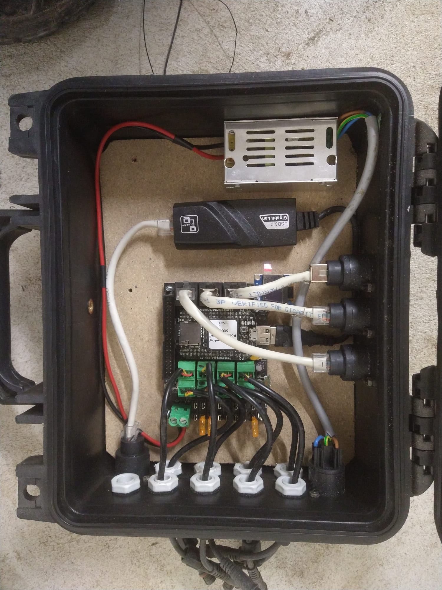
On of the big boys for many more pixels
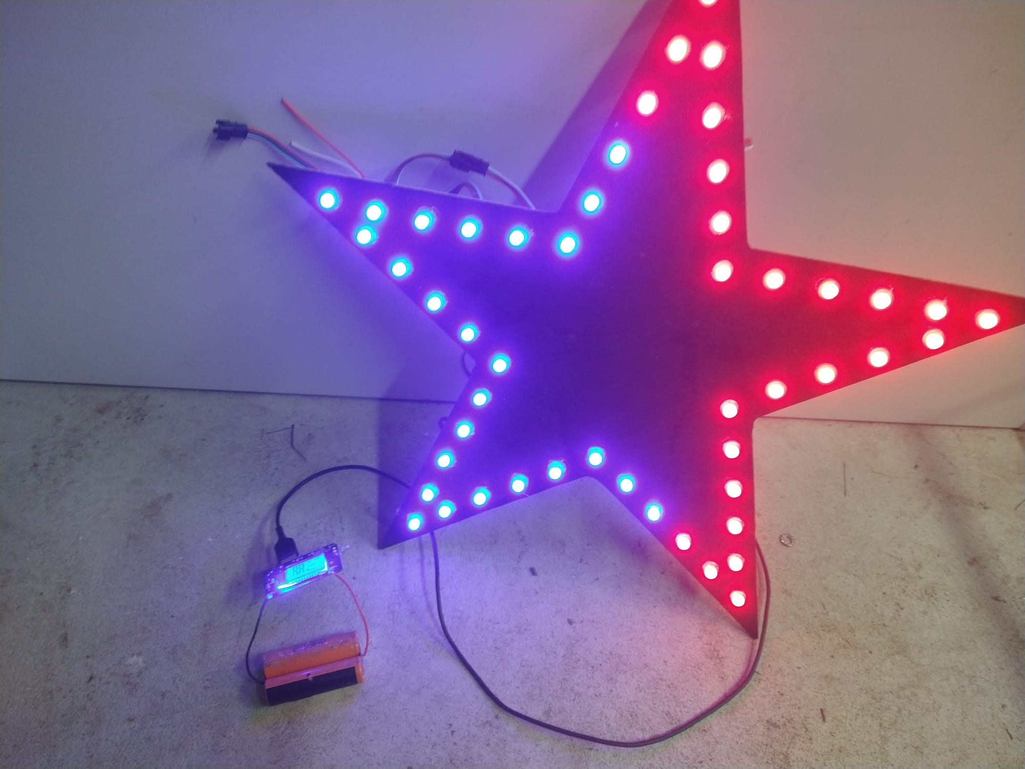
A small powerbank is all that is needed for some action!
3 Likes
Thank you so much. I have the the same setup. The only obvious difference is that I have a D1 v3, based on the esp8266. I see that you have the v2.2 which seems to have the esp12. Shouldn’t make much of a difference? I’m starting to wonder if it’s the ledstrip that is the culprit. Some of them seems toasted… isn’t this typical, right before christmas…
I don’t think the type of ESP or Wemos matters, they all output 3.3 V. Having said that, how high is your voltage to the leds? If it is (a little) above 5 V you can get problems. The ws2811 chip doesn’t get a high enough signal from the esp if the voltage is too high. If it is higher then 5V, lower the voltage, otherwise you need a level converter from 3.3 to 5V.
Ah - perhaps that’s the source of all the troubles. The DC-adapter gives out 5.14v it seems. Wasn’t aware that the leds are so sensitive to higher current. Thanks again! I will have to look for a more suitable source. I used a BMS charger with variable power supply function, but the voltage drops in a weird way when I use it as a power supply. Perhaps I should get a proper lab supply… I guess I have something to put on my christmas gift whish list 
Edit: this forum never never disappoints. I whish we could meet up for a beer, a coffe or a BBQ!
1 Like
The names are terrible. But the die/chip on the esp-12 (like the esp12e or esp-12f) is an esp8266. That part is identical. The esp-01 that Ryan is selling as a wifi chip on the skrs is also an esp8266. The esp-01 through esp-12 are all just different form factors for the esp8266. The form factor alone also doesn’t tell you how much rom the board has either. It is all very confusing.
But it gets worse. The ESP-32 came out after all that nonsense. Instead of calling it esp9000 or something. They called it ESP32, which sounds like a form factor but no. It is a die/chip. The form factors for the esp32 don’t have names (or maybe they do, but I don’t know them). They are often installed right on the pcbs, without that daughter card. There is one that fits the esp-12F pinout (sort of, but not exactly). The esp32 has bluetooth and two cores, one basically dedicated to wireless, so your program doesn’t have to respond to wifi requests.
But it gets worse. Newer variants aren’t called esp10,000 or esp42. They are called things like esp32-S3 (newer, faster) or esp32-c2 (newer, single core, slower, 8266 upgrade). The new variants need code recompiled just for them, and some features actually need different code. So you can buy things like an esp32-S3 and think it will work with the wled binary for esp32. But no, that chip isn’t supported yet (it might be by wled, but this is a problem I’ve ran into before).
It isn’t a huge problem. But they are really stupid about it. Names matter. They are the one piece of information we all know about these chips. They should make some intuitive sense.
/Rant
6 Likes
The reason they are is that they are expecting a 5V input on the data pin. To determine if the state is “high” or “low”, they compare the data signal to the input power signal.
The esp doesn’t output 5V on any digital line. It outputs 3.3V. 3.3V is higher than 2.5V (half of the 5V power input). So it mostly works. But if the power signal gets too high, and the 3.3V signal is too low, then the comparator will get confused and think a high signal is low.
So it isn’t about the power input to the leds, as much as the data input compared to the power input.
That resistor and the capacitor help smooth that out. I really think they could help. My PCB triforce is running on 5V from a usb adapter and it isn’t fickle about which one. I installed the caps and resistor because adafruit does on their boards.
If you don’t have one on hand, you can buy a logic level shifter. That will take your 3.3V input and convert it to 5V completely. They are a couple of bucks. They can also boost a signal if you are making a long wire run, or running it in a noisy environment (like a car).
3 Likes
Wow - @jeffeb3 and @kockie-nl you deserve more than a beer, I’d better get you guys half a raindeer! Thanks a lot, and thanks for your thourough rant AND explenation Jeff. I’ve been wondering how the ws2812s are supposed to work with the d1 3v logic. I’ve had several holes in my understanding, that only have made me bang my head against the wall. But now the brainfog is gone - and I feel like I somehow understand what is going on!
My wife sends you all her regards - seriously! She is pleased that my mood have lightened, and that I’m out of the “banging-my-head-against-the-wall mood”
Soo - now I have to see of the logic converters I’ve got lying are the right ones for this task. I hooope it’s bi-directional.
2 Likes
You don’t need bi-directional. The leds don’t answer…
OK, they do, but with lightpulses instead of electric signals.
1 Like
I was thinking in terms of the direction of the converter, if it supports converting both 3-5v and the opposite. Perhaps it’s obvious, but what do I know, I’m only a fine arts guy 
2 Likes
These are the ones I’ve got: 5PCS 4 Channel IIC I2C Logic Level Converter Bi-Directional Module 5V to 3.3V
https://a.aliexpress.com/_mMe261q
From what I can fathom, they should be able to do the trick yes? Edit: talking to myself here. Yes they will.
2 Likes
good luck! If it doesn’t work i will send you a working piece…
2 Likes
Appreciate it! Hopefully I’ll spare you the hassle;) if things work out, maybe I’ll get a roll and put up some holiday projects! For next year that is…
This is what I have, with 39 more pixels after the first:
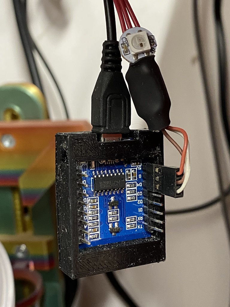
I lied earlier… it was a 470ohm, not 4k7 resistor. There is also a panasonic FP 440uF 16V cap hiding in the heatshrink. The resistor and cap are wired like this:
https://learn.adafruit.com/assets/30892
I’m guessing the reason the resistor is supposed to be there is to limit current from D4. I’ve never wired one of these without one.
4 Likes
That is a super clever idea. The leds create the output jist fine for the rest of the LEDs, at 5V. So having that one LED there probably makes a big difference. I will have to remember that next time I am struggling. Plus, having one led at the controller gives you some idea of what is happening outside. Brilliant.
5 Likes
How do the lights look after being on a long time? Did you have any issues after almost a year of being up? Do the colors still look good. I bought some white led strip lights years ago and they are now an ugly yellow color.
@Tna_331 is the light emitted from the LEDs started to yellow, and/or, do they have a plastic diffusion lens/strip that’s discolored from UV, are you in a sunny/hot climate?