Here is the post of that LR3 that @DougJoseph mentioned. I‘m thinking about doing just the same ![]()
Maybe a dumb question, but if I want 4x8 cuts the calculator says 9.25 table for this, are you just gluing boards together to get over 8ft or am I missing an option to purchase a 10ft MDF board?
I used flat MDF trim boards from Lowe’s for the rails. They come really long, beyond 10’ for sure.
The rest was a bunch of small pieces, I made Ryan’s table design.
The key is that the whole table does not need to be that long, only the edges, which I sometimes call “riding plates.” Those can be made by either buying long MDF trim boards like @coinbird mentioned, or by gluing together two shorter pieces, or by using metal struts like in my design.
Gonna go the metal strut option, should I be concerned about it riding off the metal rail?
I’ve never had it happen. Remember there is a long EMT tube referred to as “the Y rail” and the LowRider is guided by it in the long axis down the table’s length.
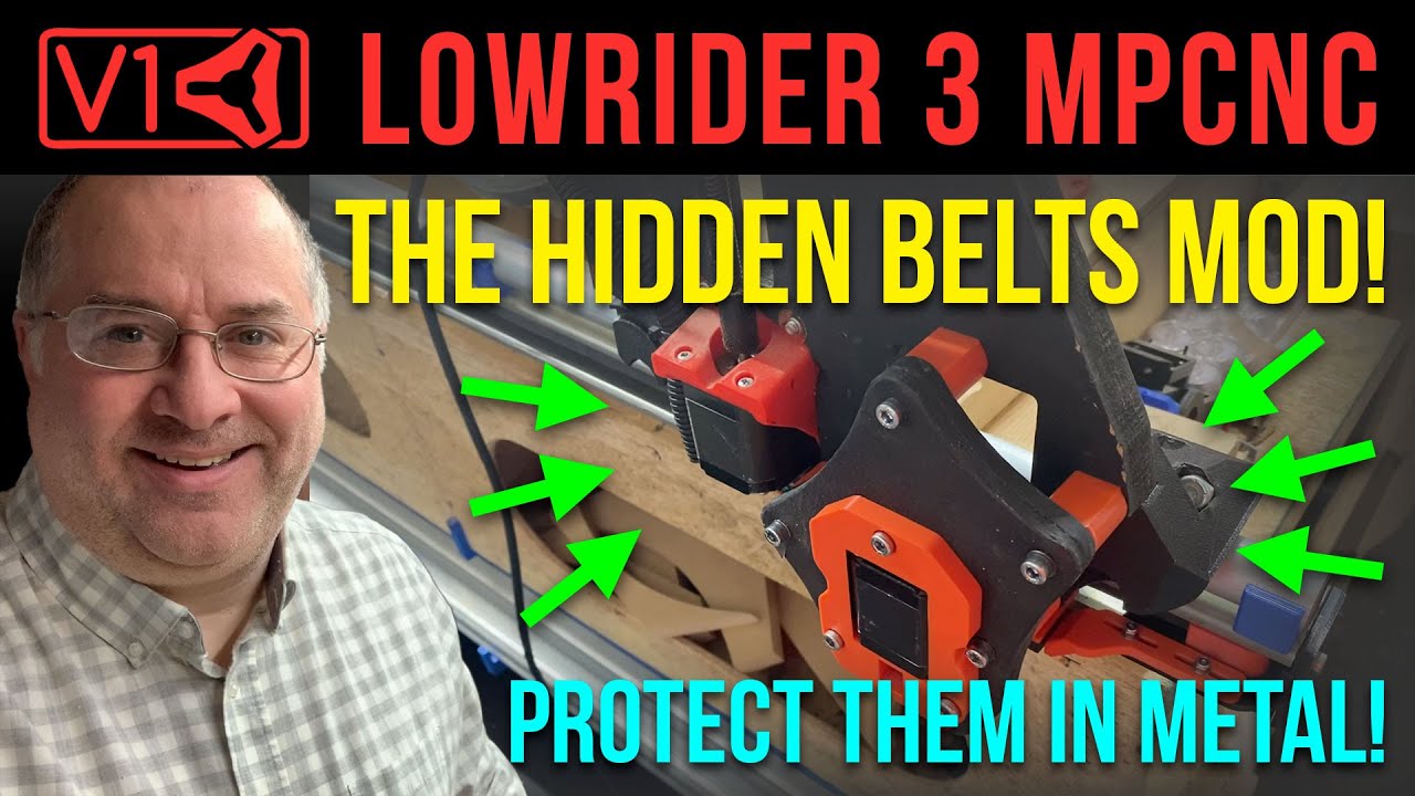
With this option, you have the added possibility of doing my mod that hides the long Y belts inside the struts. This can be done for one or both.
My video on this mod:
My Printables listings on this mod:
https://www.printables.com/model/422468-lowrider-3-cnc-hidden-belts-mod-hideprotect-either
https://www.printables.com/model/670446-lowrider-3-cnc-printed-holder-for-kobalt-routers-w
If your LowRider’s riding line on the non-rail side is different from mine, the “coupling nut spacer” part can be remixed to change its length as needed. If you run into this, I can help with the remix.
Hi! Awesome thread. I’m going to build my first lowrider, and I’m going to put it on top of @DougJoseph 's table since I need full sheet cutting area.
A question regarding materials: why MDF over plywood? I would assume the latter is more solid.
Also, beyond the preference ranking, how much better are any of these compared to others? i.e. if MDF is preferable to plywood, is it WAY better, or just slightly better and plywood and plywood will work just fine as well?
Thanks!
Ryan has formal training in engineering, while I do not. The order of preference was quoting his advice. My understanding is that preference is because, for what is needed here (resistance to warping, cupping, twisting, bowing, stretching, etc) the more homogenous an engineered wood product is, the better. Plywood, compared to MDF, has strengths and weaknesses. Among its strong points are high tensile strength. However, the wood fiber that causes that, i.e. the grain of the laminate layers, means it’s also not as resistant to warping, bowing, etc, as MDF is.
I don’t know the degree to which one is better than the other. I know plywood can work, but I also know it can bend (flex) over distance. Technically MDF can bend too, but apparently not quite as much.
My understanding of the situation is that it’s much easier to add stiffness than it is to add flatness and much much easier than it is to add dimensional stability.
MDF is the flattest and most stable option, not the stiffest nor most durable. That covers the 2 hardest problems to solve. We can make it stiffer by adding support underneath such as a torsion box structure or really any other form of simple supporting trusses etc. We can manage the durability by just taking steps to avoid/minimize any damage, making it easy to replace, coating it or skinning it with something etc.
Whether a given material is slightly better or way better probably depends on your goals. A warped table will eat some Z height, but if you’re only cutting 1/2" to 3/4" plywood then I doubt even 1/2" of warp actually matters. A warped table will take longer to cut because you’ll need to start the cut higher to clear the high spots and cut deeper to get through the material sitting in the low spots. A warped table will make mechanical engraving less consistent in small areas and potentially impossible over large areas. A warped table will make it difficult to accurate cut pockets to a specific depth.
Based on that, if you’re making a smaller design and only doing through-cuts, you could probably get away with damn near anything, and it looks like many people have. Chuck it on a sheet of whatever is laying around and replace later as necessary.
If you’re trying to make a full sheet machine then minimizing warp is probably a good approach even if you’re only planning through-cuts because having to do an extra pass to make sure you’ve got through the material could be a significant increase in total time.
If you’re trying to do engraving with a v-bit then flatness is super important so you’d probably want to prioritize that.
Of course, with all of this there are ways around it. Even if your table isn’t flat, you can surface your spoilboard which will then give you a flat surface, relative to the machine. Even if that isn’t actually flat, as such, as long as your material is flexible enough that it will follow the table then you’re fine. For example if you made a full sheet machine that had one rail level and one that rose 5mm over the length, that z=0 plane would have a twist in it, but that twist is low enough that even 1" plywood would follow that contour.
If you would only seldom do engraving then you can always either surface the piece with the machine before engraving or surface a small section of sacrificial spoilboard big enough for the job.
Also, the thing that helped me the most was to just do the easy thing to start with, get to know the machine (an MPCNC in my case) and then make changes as you go. The parametric tables are cool, but I could easily see a scenario where I’d never actually build/run the machine because I’d still be trying to design and build the table. Other people who have just bought an old solid-core door and gotten started on that have it figured out. I bought a scrap of 40mm tri-board and mounted the MPCNC to that thinking I’d make a fancy cart type thing with space for tooling etc. It’s still on the tri-board ~6 years later?
@DougJoseph i think there might be a slight issue with the files of the 49x97 cutting area, 3.625 inches tall torsion box here: your site + /for-lowrider-v3-cnc-cut-table-dxfs-for-cutting-f360-archives/
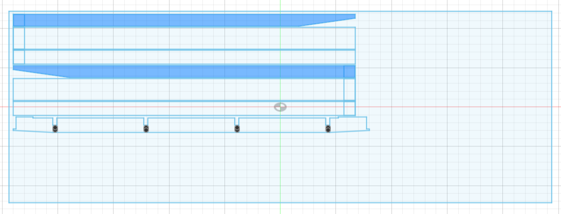
The F360 file lists 4 long cuts and 7 short ones (all in 23/32’‘). Plus, the riding plates are half inch cuts. The thing is that the pre-arranged DXF files include one extra long cut, which takes the 7th short cut to the other plate, making it appear as if that cut should also be 23/32’’ and it says so in the file. Anyways, it just makes it a bit confusing.
Good catch. Here’s how that happened. At the start, I had all the ribs (short) and spars (long) on the first sheet, and only the riding plate parts on the second sheet. However, to get that done, I had the ribs and spars close, only 1/4" between them. For use of a 1/4" bit, this closeness is what I have termed as “common cut” — where each rib or spar mutually shared a profile cut edge or two with its neighbor(s). However, I later realized that cutting it that close can possibly lead to issues with cut quality. So, I moved them apart a little and that required moving one of the ribs onto the other sheet.
There are three possible workarounds to consider. One is that the riding plates could be cut in 23/32’‘ material. Another is to manually drop the last rib onto a cut of its own, and when prepping the Gcode for the riding plate cuts, ignore the rib that’s shown there. Finally, one option is to move the ribs and spars back to 1/4" from each other, so they can fit on only one sheet, and either risk the close cut with a 1/4" bit, or use a 1/8" bit, in which case they would not be common cut. Sorry about the confusion.
I may be wrong but there might be a simpler option? I think ther’s an extra spar in the first DXF. The full table only uses 4 but there are 5 spars to be cut. If you remove that spar, it leaves enough room for the extra rib which currently sits in the second DXF.
On another note, how would you recommend aligning the top and bottom sheets to the torsion box? Since the full sheet is a bit longer than the table and there’s some extra coming out of both sides.
Wow. Sorry if I missed a mistake like that. Will correct
Thanks again for this sharp-eyed catch. Don’t know how I missed it. I have created a new cut plan file, and replaced the zip file on my website with the new one. As a convenience, here is a link to the new one:
If you think you might ever want to add a vice type clamping section to one end for doing vertical CNC cuts on taller items, like @steved did by using press screws and extra ribs he cut, which is a great idea, then I suggest aligning the tops so one edge is flush with the torsion box edge.
Otherwise, maybe just center the tops on the torsion box, with the lip on each side being about equal.
No worries, happy to help. Now that I’ve finished building the table, I think that there might be two extra missing pieces. I think that two half-minor Y spars might be missing. One more of each of the highlighted pieces so that bot sides can be completed.
I don’t know if you’ve added this to the modifications.
One final thing. When we talk about build area, is it the area that can be accessed by the center of the router? Or is it the max area that could theoretically be cut by the router with a standard say 1/4’’ bit? if it’s the former, I might need to build a slightly bigger table.
Also (I’m a bit unsure about this one), if you combine the minor Y spars or riding plates using the provided lap joints, the final length might be like 5 inches too long
Ugh. Sorry to have missed that. I have now corrected the Zip file again:
https://design8studio.com/for-lowrider-v3-cnc-cut-table-dxfs-for-cutting-f360-archives/dxf-49x97-in-cuttable-area-3-625-in-tall-torsion-box-1/
I guess I will need to check the other tables’ cut plans to see if they are missing that too.
I’m going by memory here, and that’s risky, but I think the table is based on using the V1E LowRider calculator based on asking for a cuttable area of 49" x 97" — I’m not sure if that is referring to the center of the bit or what.
If you find that you need a teensy bit more length, the only parts that would need revised would be the riding plates.
If you find that you need a teensy bit more width, then you may not need to revise the table, but you may need to move your Y-rail a bit, and/or you may need longer EMT gantry tubes on your LowRider.
Please keep us updated.
I built a small torsion box for my MPCNC with plywood because that is what I had. It warped immediately and is now 1mm off in the middle. Really annoying. ![]()

