in the last couple days, i tried to build the MPCNC. I am very amazed how everything fits together. But unfortunately, my results are not that accurate. I’m away around 0.4mm on the y axis and around 1,2mm away on the x axis. (Should be 40mm in the pictures)
Today, i double checked everything if it’s square. And it is. I already checked the belt tension and the electronics. My g-code should be fine as well. I am not allowed to upload a nc-file hiere.
I have no idea what i should do next.
I tried to upload a couple of pictures and screenshots, but new members are only allowed to upload one media file. Should i create a couple posts in this thread with pictures?
Given that the two axes have different amounts of error, the most likely culprit is the core. With the machine off, grab the router and attempt to move/twist the router to see if there is any significant movement. Even if there is only minor movement, this movement can be compounded by running at too high of a feedrate and/or not doing a finishing pass.
If there is significant movement, you want to carefully check your core clamps. There have been a number of people with issues related to yours that have found they cracked one or more core clamps…probably by overtightening the bolts.
Note that settings in CAM have been the root cause of “inaccuracies,” but those inaccuracies were the same for X and Y. This is something that can be checked out by examining the g-code if necessary.
If you don’t find movement in the core, you might want to put your pen mount back and then draw and measure some squares as a starting point to troubleshoot your issue.
Hi there, welcome to the forum! Congrats on your build.
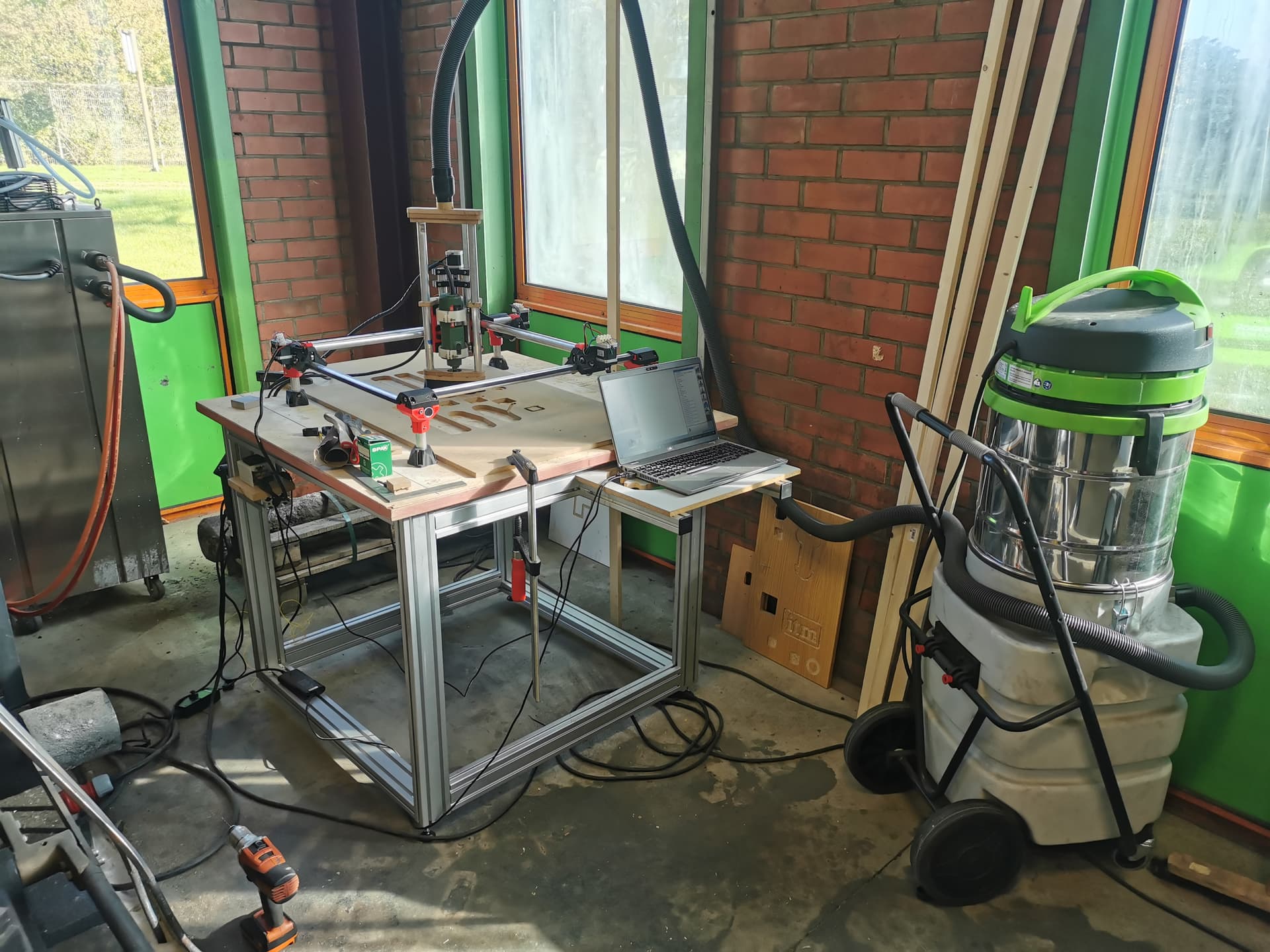
Your vacuum setup looks neat - but it makes me wonder if it makes thing pivot? Trying with a pen, without the hose attached, might give a clue.
Also standard troubleshooting advice: check your grub screws (set screws on the stepper gears). 70-80% it’s NOT the problem, but you’ll end up disassembling your entire rig the 20-30% that’s the problem, and you’ll kick yourself.
But I agree w/ Robert, double-check your core. You may have accidentally overtightened the bolts. @vicious1 did a really good job engineering the machine to be pretty much self-constraining. It really doesn’t require much force to maintain rigidity, you just need to snug it up to get things to touch. (Apologies in advance for the ableist comments) If you need a full grip, or if you’re using your shoulder muscles to tighten the bolts, it’s likely too tight.
I thought the same thing as Turbinbjorn, but it looks like you’ve hung the vacuum hose above your gantry out of frame to minimize the pivot forces on the Z-axis (which is exacerbated by having the dust extraction attached at the top of the structure).
And welcome to the madness! (I’m also in charge of initiation rituals around here)
Oh, another good test (that some of the bigger, better creased, brains can read by sight) is to rig up a pen, and run the stock test crown gcode file. That can sometimes reveal hints about what’s going on.
Take off that vaccum hose, it will never get under 0.4mm like that. Sorry to bust the bubble but that is the worst way to do it. The flexible hose needs to only be mounted at or near the core center. 2’ above it is never going to work.
Did you auto square before you ran your files? If you did that means your CAM is too aggressive, if you did not then that is the problem.
I was on my way to disassembling the rig, then i noticed one Stepper isn’t solid but the power was on. I checked the stepper and it was the set screw on the stepper gear on one of the x-axis.
Thanks for the help to all of you!
Now I’m around 0.3 mm off on both axis. That is probably the g-code`? What accuracy is possible on the mpcnc?
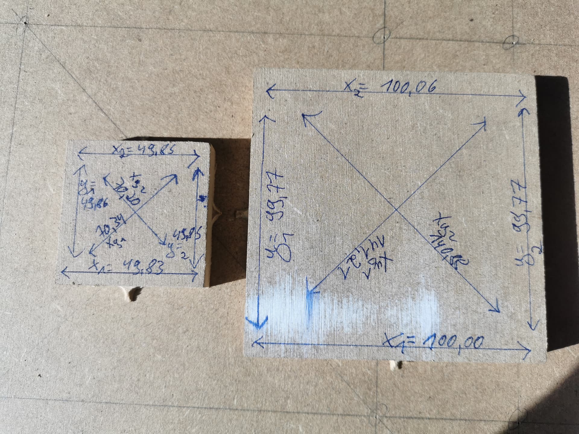
Try cutting a square 50mm and another at 100mm Run with conservative speed/doc and set a finishing pass of .25mm to clean up any blade deflection issues.
Now measure both pieces. Are they off by the same amount or does the error grow proportional to the travel distance? Are they square (measure diagonals)? Are the cut edges square or sloped (use a square) Post the results.
The machine can be tuned pretty tight even my lowrider can do .05mm for a bit but they also drift out of tune rather quickly. The mpcnc’s can do much better my burly can approach .01mm.
Realistically the limiting factor is often the runout in the router or the deflection of the small bits not the machine as long as you don’t push it.
Hey, if you close your eyes, you can see your Burly chewing through tool steel at 50mm/sec with a 1/4" bit @ 3mm DOC and 80% stepover with 0.01mm accuracy… Can you see it? Keep your eyes closed! Whoops, sorry, must have bumped into you there, don’t mind me. KEEP THOSE EYES CLOSED… Can you see it?
Beautiful, isn’t it?
Dang, I figured he’d keep more cash on him than this…
That’s a great result that I’d be happy with. It’s a teeny bit out of square but that could just be a measurement issue as the short distance is different between the pieces You might also try tightening your Y belt a bit.
Really the dimensions you are working with are like 2 passes with a sheet of sandpaper unless you are building something with extreme tolirances thats awesome. I’d declare victory now.
I just measured my unit that hasn’t been tuned in a month or 2 and I’m off by .25mm and I’m still happy because that’s better than my table saw can do.
Next step is cut the 100mm square with your normal cut settings and try a finishing cut of 1/2 the endmill width. If that looks good Then start making sawdust.
Probably that you’re using a bit too much force measuring with your calipers…
I see that you are about 0.15mm under at both 50 and 100mm. If the issue were systemic, it would be 0.15 under at 50, and 0.3 under at 100, ie: the error would scale. This doesn’t seem to be happening.
100mm is a good size for a 3D printer, kind of small for the CNC.
Another possibility is that the mill in your machine is taking a bit more material off than you have defined for the tool. This could be due to runout in your router, or softer material. Many of us deal with the cut path being narrow, resulting in parts too big, holes too small. Not fun if you are making, say, a tabbed box.
Maybe a bit of tweaking the belt tension, and getting the cut kerf width dialled in and you will be good. Only after that would I start tweaking the machine’s steps/mm.
At this point we are getting close to chasing zero’s so this is going to take a lot of testing on your part to get it better. Big differences are easy to fix, under 1/2mm takes a bit more work and really beyond what most worry about in wood. Plastic gets a bit easy to hold accurate dimensions.
I would be willing to bet that if you messed with your cleanup pass that would get a bit better. I use 0.5mm full depth a bit slower than the rough in MDF and that gets me real close.
The out of square is close enough for most people…0.1mm is amplified so you are very very slightly out of square. You can fix this with M666, and testing.
At this point the larger your test cut the easier the tuning. 100mm is not really enough to dial it in too easily. When I square my machine and test for accuracy I do it as large as possibly fits on my machine.
Also you need to add a hole in the part now to make sure you are not messing up the other side. As Dan said all components add a layer of imperfectness. So your router spins ever so slightly out of round, and your collet, and your endmills so your cutter becomes larger than measured. Then the machine flexes, tubes bend, cords and hose drag…it all adds up to a tiny bit. So out dimensions become slightly too small and inner become too large. So if you tune out the out dimensions chances are really high the inner dimensions will get worse. You are looking for both inner and outer to be off by the same amount. If you really got down to it technically the surface of your outer cuts will be smaller than your bottom, the errors add up conically The longer your Z axis is sticking out the worse these get linearly.


 Enjoy the view!