you need at least a python class in the extras, depending on how you interface with the micrometer you might also need some c code in the chelper and/or a firmware if the micrometer has an active chip that would communicate over usb, can or uart directly with the pi
But this hevily depends on how you would interface with klipper (the communication protocol)
For frontend, that has nothing to do with klipper per se and would need to go into mainsail/fluidd/klipperscreen respectively
(Let’s say the micrometer gives you an analog signal, then it’s easy: you just need a model to map the analog signal to values, take the Filament_width sensor code or thermistor code for reference)
On another note:
Were you able to test my idea with swapping the order of the pins around?
well, I dont know what the exact item you are planning to use is
the only micrometers I know are analog, so I cant really give the best answer.
If you can tell me what exactly you plan to use I can probably tell you what needs to be done and/or help you with it
(not meant in a mean way :))
I have one that is working. Its spc jnput us decoded to text with the arduino and i can change the arduino output that gets sent to klipper. What i dont know is how to integrate with klipper or where to begin with that.
It is not yet. I wrote a python gui that reads the usb serial port. Does klipper take data over a web socket or would it open a serial port like how it gets data from an accelerometer for shaketune? Im asking you because you have insight to klipper.
I can modify the arduino firmware to suit klipper input. Just have more questions than information at this point.
Adxl works cause the data is sent over SPI or i2c depending on how it’s connected to the sub MCU, which then sends it over klippers internal USB protocol to the host
Most of this stuff should be handled in chelper
Tbh I haven’t really dug into stuff like that yet but I am willing to do it.
Give me a few days so I can dig into it and figure out an interface
How real do you need the readings to be?
Cause worst case, you write them to a file and then read them from within klippy
Otherwise
You need to create some sort of communication protocol and have a sort of hook/socket in klippy
Thanks! I’m just hoping for a couple ideas on how to approach getting data in and displaying it on the klipper dashboard. Which could open the door for many possibilities.
This isnt a rush. Right now it is “streaming” data every 300 ms after receiving a “1” character and it stops when it receives a “0”. i just want it for indication only… Not for feedback control.
If you only want the data on mainsail or fluidd and not need it in Klipper internally, it might be worth a shot going directly to moonraker and bypassing Klipper all together
Or you could really have it write to a file on the pi and just have mainsail/fluidd somehow read the file and just display it.
Web development is not my strongest suit but I have done enough modifications to mainsail to feel somewhat comfortable in the code base
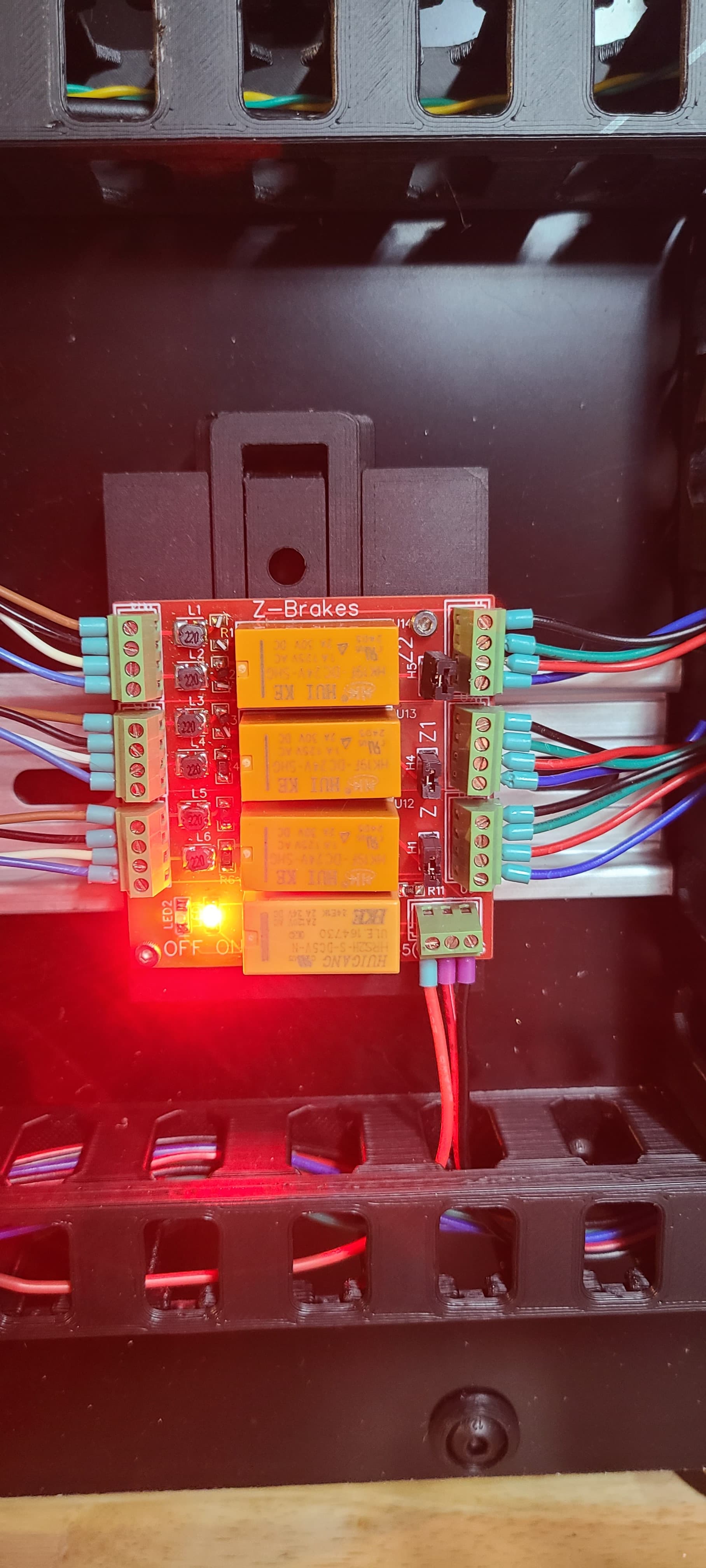
I can not seem to get my Z brakes working correctly.
I have power to the board. When I first hooked up the motor wires before I hooked up the wires to the M8P it seemed to be working. After I connected every thing it stopped.
I have a red light saying they are on bout there is no change in how the motors move by hand. before they were quite stiff.
@The_Zeanon looking to use your plugin to try it instead and It will not finish running the install. It is hung up on the connect to raw.githubusercontent.com
The board is powered by a 24v nd 5v power with a shared ground. The labeling threw one person off and it cooked the 5v relay coil. Lets verify power input first.
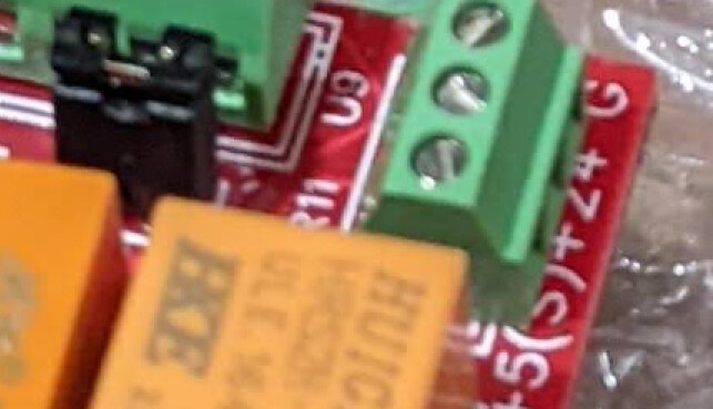
that 3 pin connector is +5V (S) is for board switching signal, +24V and then GND. the font on the silk screen didn’t fit right. the relays will normally be closed and will short the motor coils until powered.
You can test the board 5v relay by putting straight 5v on the signal/5v pin and you should hear the one relay switch. The 5v relay switches the 24v input to the other three relays that “unshort” or open the motor coil brake shorts to the motors. So if you power 5v you should hear one, then power 24v you should hear the other three. This design was to apply the auto belaying brakes if 5v signal or 24v power is lost.
I used the exact .cfg code from above. I even tried revering the pin order as suggested by @The_Zeanon . Tried to use his plugin but it wont download at this point.
I just checked whether I can download it on my printers, works on both that are currently running.
Could you try “ping www.github.com” in the linux console to see whether you can even reach github?
Hooked the 5V pin to it and the relay switches and the green light comes on.
I am mostly concerned that the issue is in my wiring. I have it wired to pass straight through in order. I believe I asked somewhere and was told the board was bidirectional so it should not matter which side the motors are connected on? When the red light is on my motors still move freely. Matter of fact it will home this way also.
The standard colored wires go to the board and the others go to the motor.
ETA: I disconnected the power and signal wires to the brake board and the printer moves as normal. My understanding is that it should not do that correct?
ETA2: If I short the windings with a jumper on the screw terminals the motor locks up. I have a feeling there is something wrong with the relays or the board itself.
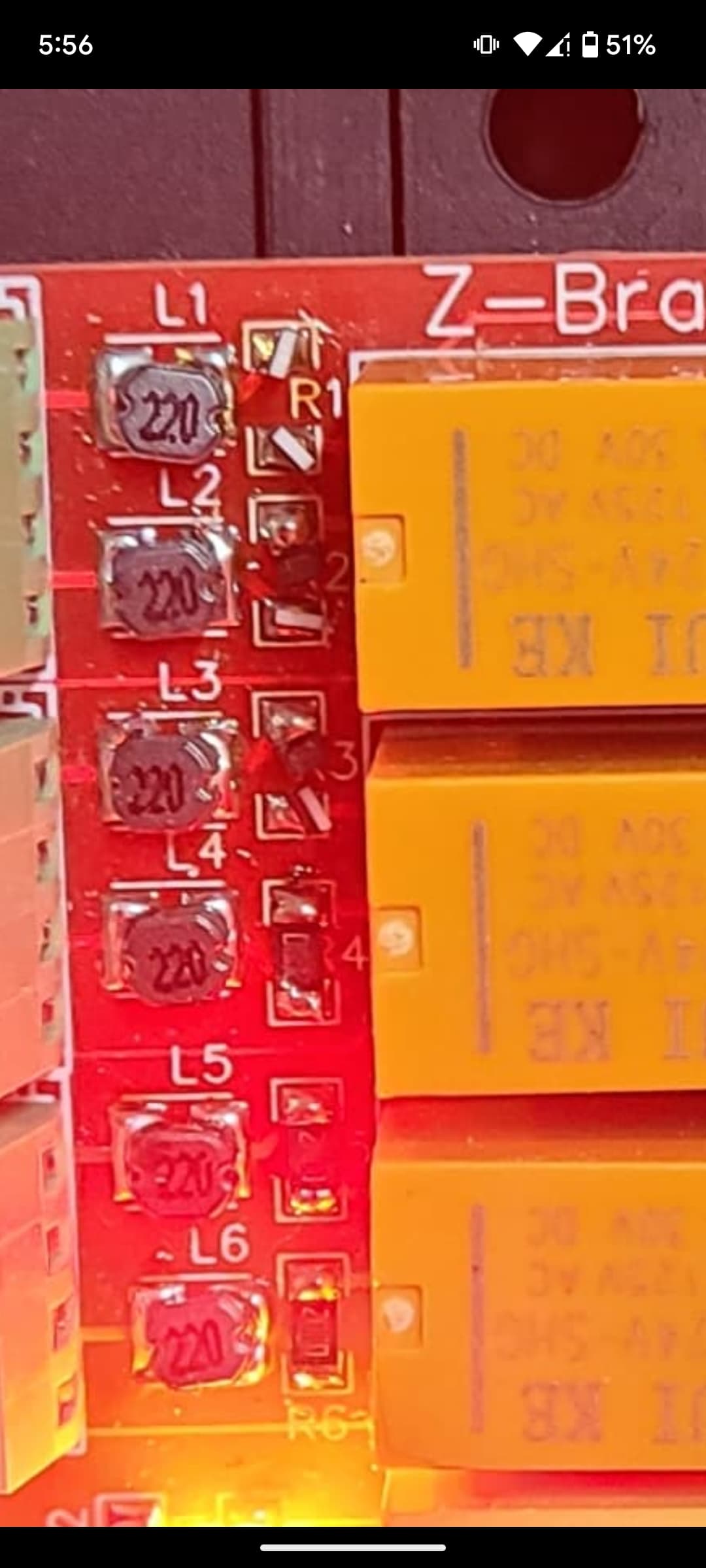
Looks like r1 and r2 are broken and missing on your board… Left of the relay… Those parts were hand placed and individually soldered by me. Looks like R1 tombstoned on both ends and the center resistor section is missing. Should cover the R1 silk screen. If you bridge those with a shunt wire. It will work. I can send you some resistors to replace those if you want.
@vicious1 can you send a picture of a new board showing the resistors next to the relays?
Also. Relay avtivation pins should NOT have ! In front.