yeah I figured that as well, thats why I already formulated my current main question.
The other question I have in mind:
When the phases get shorted, is the connection to the driver cut (basically my concern is; how to set it up so my drivers dont get fried when I keep the system on but disable the driver, in which case the brake should obviously engage as well)
I’ll write the kalico module so its cleaner to set up in a bit and post the PR here
ok, I wrote a Kalico/Klipper plugin for this:
Check LynxCrew/Stepper-Brake on Github (I cant put links in my post)
Be aware, I have not been able to properly test it, just some dry testing whether the stuff properly triggers and the stepper enable pin still works which was successfull
(once my steppers arrive and I can test whether the detent torque with the phases shorted is sufficient I will order one)
And I have another question(my understanding for electronics is very patchy so bear with me please)
I can run steppers running on 36V through the pcb withut frying anything(since my motion system runs on 36V)?
(also slightly ot, how can I edit my posts to just add stuff I forgot instead of having to write a new post everytime and thus spamming)
Click the 3 dots at the bottom to the left of reply and then click on the pencil icon. But if someone has posted after you I suggest you don’t edit, good chance your edit will be missed as it doesn’t pop up as a new post. No one here is going to flame you for multiple post.
2 Likes
Great questions. I can provide a response here for most that we arrived at thanks to input from several other users and some of my testing:
-
Function: A brake can be applied to a stepper by shorting a motor coil to itself. Each stepper (nema17 that we use) has 2 coils. By shorting one coil, it increases the resistance to freewheeling. A single motor short will be a rougher movement and produce a louder response and vibration when the motor moves compared with shorting both coils to themselves. A brake short does not lock movement, it merely slows movement and isolates the coils so a flying heated bed wont blow your controller on descent.
-
Basic setup: brakes wired with relays positioned normally closed so the coils are normally shorted will default to brake ON when not powered. In klipper i custom selected pin state on boot in the firmware and used a uart tx pin that did not have a pullup resistor on it to ensure the desired state is retained for all states of the controller.
-
Two major challenges were 1. activating when the drivers activate. This was solved by the suggestion to use multipin in klipper so it flips the relay pin when the tmc is activated for the z axis. 2. if the z motors are powered immediately then sometimes the driver would fail for a short. So a resistor similar to a motor coil and an inductor were added to the short wire to “approximate” a motor coil and the driver didnt complain.
Out of time rn. Failure modes to be discussed in next post.
1 Like
unfortunately, I dont have the edit button, only delete (I only wanted to condense my 3 back to back posts into one).
As long as no one is going to flame me for being curious, I am happy though ![]()
1 Like
You are good. Once your trust level updates. You will be able to edit.
1 Like
I know the theory behind it, I was mostly curious on the exact operation of the board, lets say our 2 coils are A1 and A2 for one coil and B1 and B2 for the other, does the board short A1 to A2 and then B1 to B2 (without shorting A and B) or does it short A1 to A2, B1 and B2?
as for the multi pin solution: while that does work I dont think its clean, which is why I wrote the plugin (I can link now, hooray: GitHub - LynxCrew/Stepper-Brake) just to make it easier for users to implement
Regarding the plugin: is it better to enable the driver and then the pin to disengage the brake or vice versa?
Same for disabling drivers, whats the preferred order of operation
theoretically I would say enable first, then disengage, otherwise we have a small window without a brake
I can also add delays if you think thats better
Sequence depends on your driver. If it can handle a changeover (open) for a split second while enabled, it will be fine. Otherwise it will e stop klipper.
ok, so I will make that selectable in the plugin, thats the cleanest and best way for users then
So the pcb disconnects the drivers from the steppers as well?
I might need a little more insight on what it exactly does though, from my understanding, if no power is provided to the board, the stepper phases are shorted.
But since we have only 3 relays from the looks of it, that means we short both phases together instead of shorting each individually right?
All the produced circuit board does is relay switch a two-layer set of relays to short motor coils and provide fake coil circuits for when the driver might error if it is a direct short.
The first relay layer the 5v relay triggered by the board pin. That first relay switches the second layer of relays that run off of 24 volt power that also feeds your motors. The 24v power then goes to the relay coils that switch the motor shorts. Your 36v power would require different relays for the second step.
If your motor power drops or your board logic power drops then brakes are activated.
Power out condition defaults to brakes are on.
But keep in mind: these are not parking brakes. They are more like autobelay at the climbing gym that don’t hold you in place, they control your descent.
I have brakes on my lowrider 4 cnc as well to slow the gantry descent of the dual z axis. But it doesnt have 2 layers of relays, it has two single channel arduino relays. I mention it because it is also run with klipper and the relays trigger off with the multipin activation of the x axis. I always have to activate x first and move it a tiny bit to turn off the z brake before homing the z axis or klipper will alarm and shut down because the tmc 2209 kicks out an error with the short because there is no resistor or inductor on it.
I have not yet seen a 2209 blow from any of my testing with 12 or 24v power activation when dealing with the relay shorting the coil or coils.
The brake circuit board can optionally short both coils (a2->a2, and b1->b2) or just one with DPDT relays. Where the single channel relay boards only do one (SPDT) so there is one for each motor, but the double brakes would need 2 more relays…
1 Like
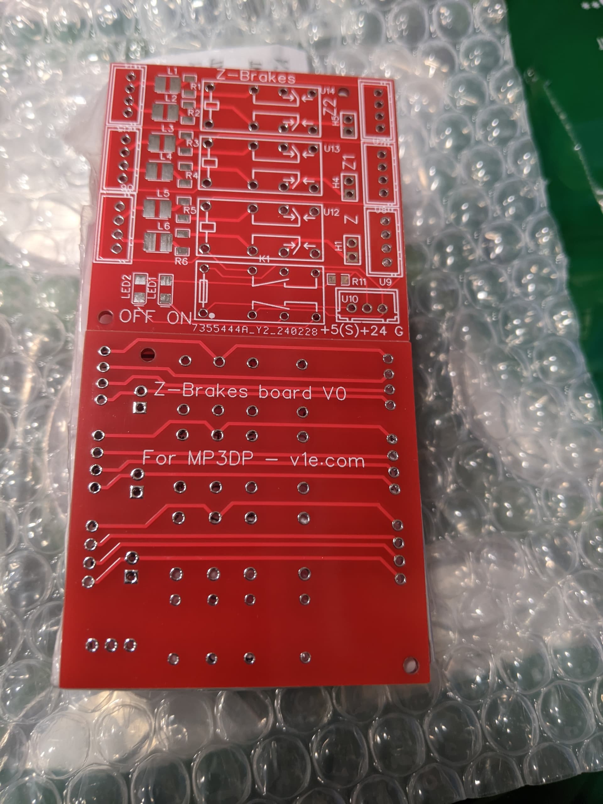
Thanks for the in-depth explanation, just to make sure: ORob's Stepper Brakes – V1 Engineering Inc would short a1-a2 and b1-b2 with no connection between a and b.
as for the 36V: is the 36V only relevant for the 24V input or also for the 4 pin stepper pass through (I have a dual PSU setup, so my motion system runs on 36V while the rest is 24V, so supplying 24V to the board itself is not an issue[well depending on how much it draws as my 24V psu is rather close to its limit])
Thanks for posting the image btw, that helped a ton with understanding the circuitry
I dont mind the bed dropping as long as there is no back current killing my drivers or it slams into the base of the printer (well I’d have to figure out z-hop but I think I have a solution for that as well)
The issue with z hop when the bed is at the bottom is the motors skip for the hop then will move up to zero.
The brake board only works if the coils are shorted to themselves and in that configuration the short protects against back emf on the descent.
I suppose if all the wires were shorted together the motor would function in braking mode, but no idea on if the driver could handle that.
thx for the in-depth explanations.
Unfortunately since it can only handle 24V on the steppers, I cant use it.
I will still endorse it for others who might want to do my mod as well and only use 24V on Z.
(I have a 350W 24V psu and the 24V components excluding the steppers will roughly draw 330W peak so I’d rather have all steppers on the 36V just to be sure)
You could make one with all 5v relays…
It can handle 125v on the stepper wires. It is the relay power switch coil that is limited to 24v.
I just looked at your klipper config you posted again and noticed you defined the stepper enable pin before the brake pin, which means that the enable pin will always be switched before the brake pin (klipper just does all of them in order of definition)
on your lowrider, could you try swapping the definition around and then see whether the 2209 still errors out
so instead of
[multi_pin z_enable]
pins: !PG5, PA9  # on octopus, !PG5 is the driver pin pulled low to enable TMC2209 z stepper, PA9 is TFT TX pin
you do
[multi_pin z_enable]
pins: PA9, !PG5
(or the appropriate pins for your cnc, but you get my idea)
Its just a hunch but it might work
ah ok, then I misunderstood you
that would be totally fine then
Since I cant really seem to figure out the datasheet of those relays too well, how much amps can they handle on the stepper wires?
1 amp it appears…
@The_Zeanon i have a side question for you about adding code modules to klipper. The adxl345 accelerometer can be connected via usb with a rpi pico and there is a firmware code set available.
If someone wanted to add position feedback with a precision micrometer -hypothetically of course- how would one go about inputting data to klipper for on-screen display, maybe something similar to the endstop indication display?
Curious.