Optimizing power delivery

How is “performance” defined?

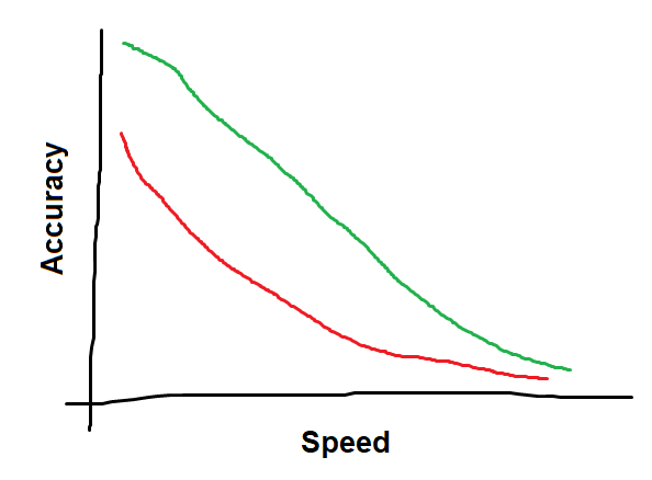
I think a reasonable definition would be an envelope of accuracy vs. cutting speed, sort of like a ROC curve (if you’re into that sort of thing). A given machine will be able to cut faster with lower accuracy, or achieve higher accuracy with slower cuts and finishing passes.

Two machines might have different achievable accuracies at different speeds (and it would depend on size among other things).

Here is an example where the green curve represents “higher performance” than the red curve, although the machine that produces the green curve might be only 12" x 12" while the red curve is from a 4’ x 8’ machine:

image

Accuracy is driven primarily by the stiffness of the machine, which I think is what Ryan was getting at earlier. The machine doesn’t “break” when you load up with high torque and high speed, but if the deflection is large and accuracy is poor, you end up with a junk part and the frame has failed to do its job, but not because it was near breaking.

Higher speed rapids could definitely contribute to the overall speed in completing a job (depending partly on what the job is).

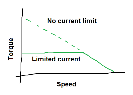
Now I’m also thinking that a roughing operation could really push the spindle, machine frame, and steppers to their maximum, and blast out a ton of sawdust (or whatever) in a surprisingly short amount of time. This would be a scenario where you’re beyond the usual loads where the frame retains its usual accuracy, and you would really not want the steppers to skip steps for example. This is the situation where the stepper torque at speed could actually matter a lot.

For any sort of accuracy at all, the torque and speed will be light and slow, and the performance (meaning speed vs. accuracy of the finishing pass) is 100% driven by the stiffness of the frame. A stiffer frame can support slightly higher loads and maintain the same deflection, meaning either higher feed rates or deeper cuts, both of which decrease the time to complete the finishing operation. Motor torque and speed are not factors in this regime.

I think mentally, people (at least for me) tend to think primarily, perhaps even exclusively of the slow, precise, and lightly-loaded operations. I would venture that this is the reason for the push-back, since the available stepper torque and top speed do not contribute at all when operating in this regime. As long as I can get the accuracy I want and the speed is “fast enough,” I’m happy.

Roughing speed and rapids are valid things that do affect overall performance (according to my definition), especially if you are trying to push the throughput to the limit. But outside of a drag race, most are not concerned about throughput, so it is rare that they get attention.

1 Like

Almost. But there is still the fact that we need to reach our 1A per coil. If the coil is 3Ohms, and we need 1A, we need to have at least 3V to reach our 1A before we turn off the power supply. So we only have 2.4V of “room” left. But as long as you have more than zero, your power supply will turn off, and any extra bolts won’t change things.

1 Like

But the voltage isn’t constant. The driver is turning it on and off to make the current constant. So P=I2R is really the power equation that matters. And the current and resistance is the same with 12V and 24V.

4 Likes

lol. Right. :man_facepalming: I realized that it comes down to that constant current driver. Again.

2 Likes

With constant current sources the load is in series with driver and connected directly to source. The circuit can interrupt the flow of power but it does this after the motor. In other words, there is no scenario where your stepper driver is only sending 3-4v to the motors. They are connect directly to 24v but that power is interrupted such that the average current is the desired current. Some drivers do this via adjustable resistors and others do it automatically.

That’s the point. 24v has a broader range of circumstances where the parasitic resistance is not an issue. I agree that it’s best to run large enough wires that your motors see the full source voltage with almost no parasitic losses. That being said, stepper motors are only a small item on a long list of things that might need power. There can be fans, relays, etc, all of which are much less picky about the size of the wire thanks to a higher source voltage.

As I was saying earlier, you start to notice the drop in torque immediately especially for 400 step/rev motors. It just depends on how much you consider significant and that depends on a lot of factors ranging from how much your machine weighs and the friction losses of your rails and bearings which combined decide your acceleration and your acceleration combined with the size of your machine decides the fastest you can move.

My stepper motors are 0.65 nm but the pulleys are about 9.5mm in diameter bringing the force up to 1.74n of force. If your machine weighs 25 kg that’s a max acceleration of 139.2 mm/s. Adding in a 20% safety margin you are looking at 111 mm/s.

Since torque drops the faster the machine is moving it means the acceleration goes down. Your max speed is then limited by the acceleration and the length of your movement commands. You have torque changing as a function of speed, speed change as a function of acceleration, acceleration changing as a function of torque.

The biggest constraint is then if you can reach a certain speed in typical movement command on your machine which depends on the size of the machine in addition to the other factors. My machine has an 8’ working area on the Y axis. That’s about 2500 mm. That means, going from end to end, my top speed would be 417 mm/s (assuming it weighs 25kg). It could go faster, but it wouldn’t have time to decelerate and would crash. Now we add in the contribution of the torque going down as a function of motor RPM. To do this I’ll use a lookup table which has normalized values from graphs that can be found online. That brings my top speed down to 310 mm/s for 12v. For 24v it’s 368 mm/s. That’s assuming the weight of the machine and no drag forces but it gets the point across. There’s a substantial drop in top speed for the longest movement commands I can do. Shorter movement commands are even more limited by the machine mass. At 1m it could achieve a top speed of 176 mm/s for 24v and 164 mm/s for 12v. At a 1 cm movement I could achieve 5.6 mm/s for 12v and 5.8 mm/s for 24v.

Does an increase from 5.6 → 5.8 matter? It’s roughly 4%. If you are doing something that takes 12h to cut, that’s a reduction in time by about 25 minutes (this assumes there are no movement commands when in reality those take up a big portion of the project time so this would in reality be much larger than 4% due to faster movement commands).

All of this is highly dependent on factors I could not possibly know about your personal machine, e.g. motor torque curve, motor torque, voltage as measured at the motor, the current given to the motors, the size of your machine, the weight of your X carriage, how much friction there is on each axis, the list goes on and on. These are just examples to give an idea of what to expect. You would see higher torque coming out of the motors with 24v, even at lower cut speeds, but if this is significant or not depends on a host of parameters only you could know.

1 Like

I am missing something here. If you have 0.65 Nm, or 65 N cm, then that means you would have 65 N of force if you had a radius of 1 cm. With a radius of 0.475 cm, your force should be 65 / 0.475 = 136 N of force. Then if your machine weighs 25 kg and you have F = ma, so 136 (kg m/s^2) = 25 (kg) * a (m/s^2) and your acceleration is 136/25 = 5.47 meters per second per second. So roughly half the acceleration of gravity.

Linearly decreasing torque as a function of speed is typical for a DC motor and other types of motors, provided they are not current limited. With a driver that has a fixed maximum current, the torque curve will be flat over a wide range of speeds, and then at high speeds the current is no longer the limiting factor and the torque will decrease linearly beyond that.

image

More voltage with no current limit will move the line up and to the right, providing more torque at every speed and a higher top speed, but when the current is limited, the torque is also limited, and it is limited to the same amount. Only in the high speed zone where torque is decreasing will you see an increase in torque.

2 Likes

This is exactly right. But the motors do see an average of 3-4V. The driver is connecting 24V for 12.5% of the time or it is 12V for 25% of the time. The real speed limit is when 12V is on 100% of the time and 24V is only on for 50% of the time. Above that speed, you get the 12V setup losing torque, but the 24V is still getting close to the max torque.

The default LR firmware has accelerations capped at 180mm/s/s. It is definitely too low (to be conservative for new users). But also, 5000mm/s/s would be pretty darn quick. Drag is probably playing a bit part.

1 Like

Do we all get a PHD after this!? I mean you guys probably have one, but I want to be called Doctor as well.

Is there a quick and dirty test for this? Theoretical vs practical is my favorite testing. Clough42 did a stall test (What's the best NEMA23 Stepper/Servo? | Electronic Leadscrew Part 24 - YouTube), but what if I just hung a weight from a larger pulley and tested acceleration of both Power supplies to see at what point if any we show some changes? So from rest to full speed, and just keep ramping up acceleration until it fails.

1 Like

At one point I had wanted to make a test pattern that would test accelerations and speeds. Ideally you run with a pen and it would be clear at what point it begins missing steps because the marks don’t line up anymore, or something. I sorta dropped it, but I think it would definitely have value, so I can revisit that idea.

Then beyond that, running with a load, like a hung weight like you said, would also be an interesting test, but more involved to set up if it needs extra paraphernalia. I would like to have a standardized test of stiffness when the steppers are not skipping steps.

1 Like

That is a better idea. Then you could test each axis individually. Marlin is starting to separate out travel accel vs work accels as far as I remember Since G0 is now a thing for Marlin. Might be the time to start fiddling with them anyway. Simple as a 100mm line with a start and end marker, M201/204, move over, rinse and repeat?

Oh, looks like there is non-extruding G1, extruding G1, and G0 accels…might need a dial indication instead of a pen test. Check for the same start and end location.

A skipped step will be at least 1/50th of a stepper revolution, or about 0.64 mm, so it should be visible. The max acceleration is probably not uniform over the workspace. If the center assembly is in the middle it is equally supported by two belts, but near the edge one belt will be responsible for more than half of the load. Also probably not good to remove the router to measure accelerations because it would be lighter and not representative.

1 Like

We would need to test at a worst case, so at one side, fully loaded, Vac running even. Then figure out a safety margin.

At the same time, that says nothing about during a cut in specific materials. But it would be great to know A real world max accel, and how much difference 24V makes.

Wow. this thread took a weird twist in the middle…

I’d get a drink, but I’m in the middle of my company’s annual all-hands meeting…

2 Likes

As this thread has become more civil, the content has gone ballistic! I’ll never understand all the math and science, but it’s amazing the knowledge and experience in this community.

Thanks to all, I really appreciate it.

Mike B

3 Likes

It’s the tangential force, not the torque. The tangential force is also useful because you can estimate your feedrate and RPM. Aluminum generally requires 800n per mm^2 to cut. That’s a tall order for a nema 17 motor. If your router is spinning at 27,000 RPM that’s 450 revolutions per second. Moving at 1 mm/s with a single flute bit the contact area will be 1/450=0.002222 mm wide. If your cut depth is 1mm, the area of contact is then 0.002222*1=0.002222. The force needed to cut this is then 0.002222*800=1.7776n. That’s a tall order when my motors can handle only 1.7n. If you want to cut aluminum at reasonable speeds/depths you have to go with a machine that uses NEMA23’s or you need planetary gearboxes for your NEMA17 motors or a bit with a higher flute count.

Since a typical planetary gearbox has a 10:1 reduction that means your torque will be almost 10:1. You lose some from spinning at 10x the RPM for a given movement speed. That allows you to do the same cut but at 10mm deep or a 10 mm/sec feedrate. You would probably run into overheating issues.

Going with a higher flute count reduces forces as well. If you used a 4 flute bit it basically cuts the contact force by a quarter. This is due to the fact that it makes 4 cuts per revolution which is 1/(450*4)*800=0.45n. The same cut above could be done at 4.5 mm/s movement speed or depth of cut. That’s a much more reasonable option for most LR2/MPCNC users.

I made a lookup table for the torque curve of some motors online and normalized the values e.g. scaled them as a percentage of the peak torque. If the RPM of the motor fell between two points in the table it was interpolated linearly.

That makes perfect sense.

I would run at a fixed feedrate and measure the motor power draw. At high acceleration forces, to counter-act drag, the resistance in the windings will be higher and the TMC2209’s will bump up the voltage to compensate. From that you could calculate your drag coefficient for each axis.

Yes and it’s very different from receiving 3-4v. It does receive a full 24v but only in a series of on/off pulses that average out to be 3-4v total over time.

Tangential force is simply torque applied at a distance, which is what he said. 0.65Nm is 65 Newtons at 1cm. Since a 16T pulley is significantly smaller, (Circumference = 32mm is a diameter of 10.2mm, or a radius of 5.1mm, so that’s about 127N of force. Assuming of course that you’re using 16T GT2 pulleys.

No, it actually isn’t significantly different because it’s an inductive load. Inductive loads increase resistance for higher changes in voltage. Since it’s really WORK that we care about, as in the ability to apply a force over a distance. Keep in mind that the switching frequency of these drivers is very fast. The datasheet for a Trinamic 2209 lists 12MHz as its switching frequency. At anything under what 12V can do, there’s no way that the motors are ever passing current anywhere near what they could from 24V.

I’ve been reading a lot of stepper motor and stepper motor driver specs lately, and one thing that the specification sheets do not provide is power voltage. They list a nominal low voltage, required to generate the max holding torque current, but do not specify a driver voltage. The drivers do list voltage, but as a maximum of what they can handle switching. Again, current handling seems to be the big differentiator.

So, what this means is that the amount of power that the stepper motor has is only related to current. Increased voltage does not confer or imply increased torque. (Tangential force, if you like, which is simply torque applied at a distance.) As such, provided that your power supply is capable of supplying adequate voltage, and that your driver is not oversupplying current, the amount of power that the motor can apply is determined by average current.

I think I’m going to do an experiment. I’m in the 24V camp myself, since I like the extra speed headroom, but I do not think that it applies extra power.

So, I’ll run a stepper off of my Duet. With the same firmware, the stepper will have the same current settings. Same motor, same control board, just 12V, and 24V power, and measure the amount of force that it can deliver to a belt on a pulley. I fully expect that the mount of force that it can deliver will be the same, until I exceed the speeds that 12V can supply. If I’ve missed anything that you think I should be measuring, please let me know, and I’ll try to include it.

2 Likes

I strongly disagree with that statement since running 3-4v across a 2 meter 24 gauge wire will produce a substantial voltage drop that severely limits current while 24v at a duty cycle of 12.5% will not see any voltage drop that limits current.

If there was any confusion, I further clarified in the followup post. The tangential force of my motors for a 16tooth pulley is 1.7n. Based on that amount of force, a 25kg machine that has 2500mm working space, you’d see a 4% increase in top speed for cut movements 1cm long by switching to 24v. Larger movements commands produce an 18% increase. Originally you said it would make “no” difference. I am showing you that is quite likely not true. It does make a difference. Whether that difference matters depends on your machine, namely the acceleration, weight, drag losses, and the size of movements that you are performing which is limited, in part, by your work area.

If you want to calculate for 127n we can do that to. Keeping everything else in my example constant, the top speed for a 1cm movement command would be 255 mm/s at 12v and for 24v it would be 290 ergo 24v is 14% faster.

:man_facepalming:

That’s because it adjusts the average voltage to keep the current constant. When under load, the impedance in the coils is higher which requires a higher voltage to maintain the same current. Stepper motors have another effect at play namely to make a step it has to energize the next coil in the sequence which requires recharging them. The recharge time is dependent on the source voltage. Higher voltage recharges the coils faster. Think of it this way. The motor is supposed to have a set current. A higher voltage produces a higher current flow. To keep the current at the spec’d amount, it has to duty cycle it, e.g. turn it on and off. The average voltage/current is the same, the difference is that the voltage/current spike is much higher and coils charge faster. A 24v power supply at a duty cycle of 12.5% averages out to 3v but it produces the same amount of power in 1/8th the time period. That’s why it has to be duty cycled. The time it takes to charge the coils is usually not consequential, unless you are doing this many times per second. If your motor is rotating 10 times a second and it has 400 steps per rotation, it must recharge the coils 4,000 times a second. On those scales, the recharge time in the coils is significant.

Maybe this will do a better job explaining it than me: http://users.ece.utexas.edu/~valvano/Datasheets/StepperDriveBasic.pdf

Inductance makes the motor wind-
ing oppose current changes, and there-
fore limits high speed operation. Fig-
ure 2 shows the electrical character-
istics of an inductive–resistive circuit.
When a voltage is connected to the
winding the current rises according to
the equation
I(t) = ( V ⁄ R ) · ( 1 - e– t · R ⁄ L )
Initially the current increases at a
rate of
δI⁄δt (0) = V ⁄ L
The rise rate decreases as the cur-
rent approaches the final level:
IMAX = V ⁄ R
The value of τe = L ⁄ R is defined as
the electrical time constant of the cir-
cuit. τe is the time until the current
reaches 63% ( 1 - 1⁄e ) of its final value.
When the inductive–resistive cir-
cuit is disconnected and shorted at the
instant t = t1 , the current starts to
decrease:
I(t) = ( V ⁄ R ) · e– (t-t1 ) · R ⁄ L
at an initial rate of
I(t) = – V ⁄ L
When a square wave voltage is ap-
plied to the winding, which is the case
when fullstepping a stepper motor,
the current waveform will be smoothed.
Figure 3 shows the current at three
different frequencies. Above a certain
frequency (B) the current never reaches
its maximum value (C). As the torque
of the motor is approximately propor-
tional to the current, the maximum
torque will be reduced as the stepping
frequency increases.
To overcome the inductance and
gain high speed performance of the
motor two possibilities exist: Increase
the current rise rate and⁄or decrease
the time constant. As an increased re-
sistance always results in an increased
power loss, it is preferably the ratio
V ⁄ L that should be increased to gain
high speed performance.
To drive current through the wind-
ing, we should:
use as high voltage as possible
• keep the inductance low

There is a big difference between saying, I can’t reach 6mm/s and I can’t reach 290mm/s. I care a lot less if I can’t go over 250mm/s.

I agree with that article, but I don’t think it is saying the same thing as you. The important analysis is, when do you cross from the first graph, where the speed is low enough to reach saturation, into the third graph, where you are more reaching Imax? I think we all agree that that crossover point is higher in a 24V supply vs. a 12V. The question is, is that number large (over 100mm/s) or is it going to have an effect on typical MPCNC milling operations?

But I think the point you were trying to make is that the slope of the rising edge was higher with a 24V PSU. And in that moment, you would have more torque than with a 12V. I don’t think the article is claiming that. And I am honestly not sure how much impact that has. Stepper motors always have a “jump” between steps (or microsteps). Maybe that is where that little bump in torque from voltage comes from.

Not sure what you are trying to argue here. But Dan is right. The current is what matters, the voltage is just a way to get the current.

2 Likes