Optimizing power delivery

I did some trial cuts over the weekend on a piece of 18 mm pine plywood to dial in the feed rate and DOC. The best I could get with a 2 flute 1/8" upcut carbide endmill is 4.5 mm DOC @ 420 mm/min. Beyond this, the machine starts skipping steps. I have a feeling, I should be able to extract more performance from my LR2. My benchmark is the actual performance I get from my MPCNC and the theoretical calculations from this website.
If I were to throw money at this problem, what would be the best bang for the buck or in case there are multiple areas, what should be the priority in which I should address them? And yes, I have checked my pulleys :slight_smile: … twice. Also, there is no binding on any of the axes and the belts are 10 mm and I have not tightened them like a guitar string to avoid putting excessive load on the motors. I have also removed the vacuum hose to eliminate that source of resistance.

Here is a list I could come up with:

  • Drivers: The LR2 currently has a mix of DRV8825 and A4988 drivers (whatever I could find in my stash). The X-axis (along rails) has a single stepper powered by DRV8825 set at 2A. The Y axis (along the table length) and Z axis have 2 steppers each (as per the design) and are powered by A4988 set at 2A. The few times I encountered missed steps, I would bring the machine to X0, Y0 to see which axis is the problem. Almost all the time, it was the X-axis. One option is to increase the driver current. The motor was not too hot to touch. So, I think I may have some room there. Ofcourse, the other option is to just get a better driver in which case, are there any recommendations?

  • Power adaptor: The adaptor can supply a maximum of 3A at 12V. When I was testing the machine without any load, I saw the maximum current was between 2A and 3A. I can hook up the current meter while the machine is actually cutting and see the current spikes. Unless, any of you think that, regardless of what I see on the meter, I need to get an adaptor with a high output current. I believe, Ryan recommends 6A.

  • Stepper motors: The machine is using Nema 17 59Ncm (84oz.in) motors. Should I get a bigger one or has someone seen miracles using a specific make?

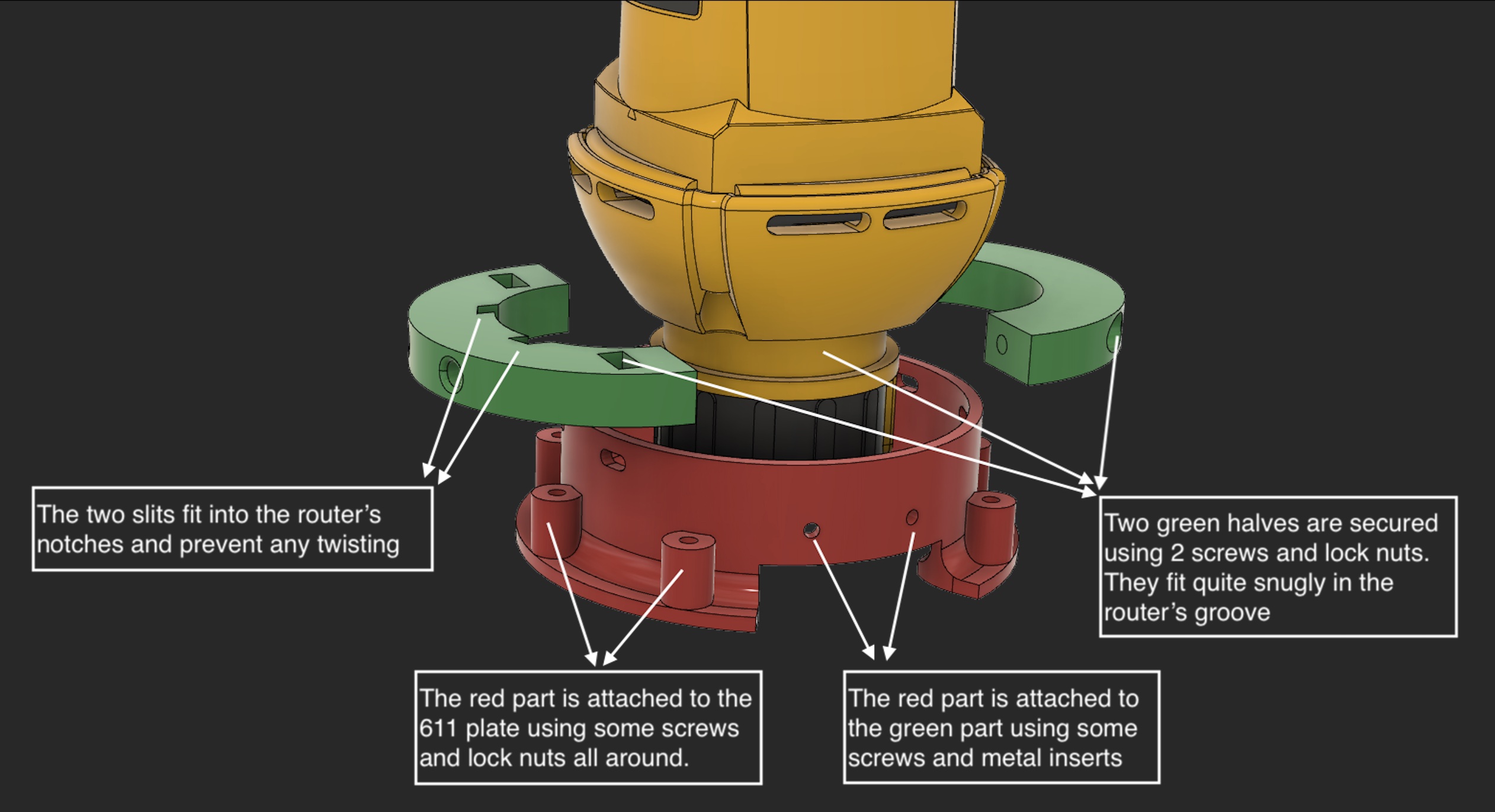
  • Router: I borrowed DW660 from my MPCNC and 3D printed an adaptor to use it on the LR2. Could this be the bottleneck? Should I spend money and get the real router? DWP611?

  • Endmill: The router uses not too expensive CNC endmill. Is this what going to get me the maximum boost for the price? Again, any recommendations?

  • LR2 Size: The X-axis is about 4’6" and the Y-axis is about 8’. I am not sure how much of a role does the size and therefore, the rigidity plays in performance. I cannot shorten the X-axis but I can try to shorten the Y-axis if ppl think it might help.

1 Like

Are you sure it was 420mm/sec? Im pretty sure the firmware has it capped at 40. As you must have read elsewhere already the key to increasing your cut speed is taking deeper cuts. I’m typically at 6mm DOC AT 30MM/SEC

Oops. I meant 420 mm/min. I fixed it in the original post. Thanks for pointing that out.

Not sure if I understood that. If I go deeper in a single pass, won’t it mean I need to go slower? The deeper the cut, the more is the stress on the endmill.

1 Like

Thanks for sharing your numbers. What material? Is it with LR2? If so, can you pls share your configuration in terms of the router, endmill, drivers, steppers, size, etc?

A little slower on a deeper cut still gets the overall job done faster if you eliminate a full circuit repetition.

Thanks Tom. I understand it now and can play around with it. However, I am still looking for an answer to improving the fundamental performance of the machine itself. Would you have some inputs on that based on your own build if you have an LR2?

I didn’t go as fast on my lowrider as I go on my primo, but still…that’s way slow, especially for the 30k rpms the 660 gives.
Back of the envelope says you need to triple the feed rate to be safe from burning your endmill (maybe 2.5 would be ok) or switch to a single flute and just double it.
You should absolutely be able to go faster than that, so make sure you have a quality endmill. The ones Ryan sells are a good start.

1 Like

Sorry, I’ve got a Burly, not an LR2.

That would be in birch ply, yes it’s a lowrider, my x is about 28in so it’s nice and ridgid. With your wide x you will see quite a bit more deflection but it should still be able to cut faster. I do have aluminum z x braces but that just helps with precision. I’m using the Makita router and running dual flute endmills. I believe it’s the same ones Ryan sells in the store. Drivers and steppers are all the standard ones that Ryan sells in his kit.

Are you sure you have those wired in series? I suspect that might be a wiring in parallel issue.

If the motors get too hot (above about 50C) they will deform their pla mounts. If the drivers get too hot, they will shut off until they cool down. Like 30 seconds.

So first, I would make sure the wiring is right. You can post some pictures and we can take a look.

If something is loose, like maybe the 660 mount, then the bit can jump and take a huge bite, which will increase the load dramatically. If that happens, you will skip steps, so watch it carefully to see if that happens first before it skips steps. A good warning sign of that is the bit will wobble sometimes and make wider holes, but not skip steps.

From your list, if you have evidence your PSU is dropping below 12V, then I would get a beefier one. You are operating out of spec if you are driving 5A from a 3A PSU.

If you are suspicious of the bits, then I would buy at least one good one (try to find one like the single flute ones Ryan sells in the shop). That will give you a reference to be able to measure against for your other bits.

Unless your drivers are broken, I wouldn’t get new ones. The steppers are probably fine. The 660 is a good CNC router, IMO.

You will always get more rigidity in a smaller size (probably by a power of two, so half size is 4x more rigid). But that will only help you not skip steps if the problem is rigidity. If the bit wanders because the tubing is flexing, then that can cause it. If that isn’t what you’re seeing, then it is not going to help.

My guess is the weakness in your setup is either electrical (wiring, PSU current) or something is floppy (and the mount is my biggest suspicion, because we haven’t seen that before).

1 Like

@jeffeb3 thanks for your detailed reply touching upon different areas. I certainly owe you some of the details you asked for and will do so shortly.

One idea that came to me to triage the issue, was to get the endmill quality out of the picture and just intentionally ram the bit against something that is fixed (like the side of the spoil board) with router turned off. I left the Z and Y axes disengaged so that I have more current available for the X axis (kind of temporarily addressing any PSU issues). Now, at the time of “stall”, it is either that the rotor is really stalled or the belt is slipping. And I should be able to see it visually. Turns out that the rotor still continues to move. So, my initial assumption of the stepper skipping steps because of rotor stalling was not really correct. The culprit seems to be the belt tension (may be there is more than one issue but we will peel the onion one layer at a time). I gradually increased the tension till it was the rotor that started stalling. That is my crude way of knowing how much to tension the belt. I have not tested it with actual cutting. Will try it after work and will post the results.

I am happy to report some progress based on some 30 min of testing time I got on the machine today. With the above change, I was able to incrementally boost the speed to about 510 mm/min, an increase of about 20% from 420 mm/min. The bit did not show any signs of wobble at this speed. I will continue with my testing tomorrow incrementing it 20-30 mm/min at a time until I hit into the next bottleneck. Wish me luck!

3 Likes

I see some hope! The latest stunt I tried was 6 mm DOC and 600 mm/min in plywood. It went through fine. However, the meter showed the current saturating at the PSU’s maximum output level (3A). So, I am going to push the machine further only after I secure a 6A supply and some good endmill.

Just answering some questions from the thread below.

I have the dual endstop configuration. So, each motor is wired separately to its own driver on the Ramps 1.4 board

It is possible. I will keep an eye. I certainly need to get some more mileage on it before I am confident. BTW, here is a diagram of what the mount assembly looks like:

2 Likes

Do you have any bracing higher up on the spindle?

1 Like

My original design did but then I thought of just giving it a shot without that. From what I have observed so far, there is not a whole lot of deflection while cutting and the quality of cuts have come out ok. The disclaimer is that I have not done a whole lot of cutting yet. I will know more in the coming days/weeks. I have a feeling that adding a brace might help more in terms of the durability than the accuracy itself.

The heavier your depth of cut, and the faster you try to move through the cut, the greater the deflective forces will get. The tool mount on the MPCNC Burly that I use has a band up high on the motor housing to help keep things rigid. As I understand it, the LowRider was initially designed to hold a router, which has a wider ring around the bottom, which would be much more rigid. It might be interesting to hear from others using similar tools on the LowRider and learn from their experience on tool deflection.

I trust that you are the expert in this brace (since you are the only one that has touched it, and you designed it). But here is my $0.02:

The router has a long moment arm. If you had just a little brace at the top holding it there, the bit would be much more rigid. I would think about the bottom brace as stopping translation (movement in X, Y and Z) and the top brace stopping rotation.

@ttraband @jeffeb3 Thanks for your feedback. I agree that adding a brace at the top should help with the rigidity. I will go ahead and add it.

I’d get some TMC2209’s or better. The largest nema 17’s can overheat a TMC2209 even with active cooling and the TMC2209’s have many nice features like software level current control.

24V is an absolute must as long as your control board supports it. In fact, the highest your board supports is the best. If your board supports 36v or 48v, then go for it. Stepper motors have much higher torque especially at higher RPM values with higher voltages. It is due to the time it takes to recharge the coils as it takes steps. If you are turning the motor too fast the coils can’t fully recharge and this limits torque. Higher voltages recharge the coils faster. Additionally higher voltages reduce the size of wiring you need to run which reduces cost and makes the build more nimble.

I’d get the highest torque ones you can find with no more than 200 steps/rev. Microstepping at 2x resolution with 200 steps/rev will produce an accuracy of 0.2 mm which is far lower than the human eye can perceive. You will probably have greater inaccuracies in the stretching of your belts & bending of your machine and cutting bit not to mention grain tear-out. Lower steps/rev have higher torque at higher RPMs so you can move your machine much faster.

Also one mod I did that is easy to do and greatly increases performance is to install a second X motor. You delete the vacuum port. It’s pretty straight forward. Dust can build up on the rails and cause the motors to skip steps or even become stuck. After installing two large nema 17’s I have never had the X axis stick since.

With the stepper motors maxed out, the DWP611 absolutely becomes a bottleneck. Although at those levels the stiffness of the machine and belts also become a bottleneck. On my machine if I push the motors to the maximum the belts will visibly droop and the router’s tone will change indicating a drop in RPM. In other words it isn’t really practical to push a LR2 to the point a DWP611 router becomes the bottleneck.

I like 1/8" upcut spiral 2 flute bits in general. Up-cut is best since it helps to clear out chips. For aluminum I’d go for a single flute 1/4" bit since it is stiffer but you can run 1/8" bits if you reduce your speeds. Definitely go with carbide bits as they last much longer.

My LR2 has a working area of 4x8’. That’s pretty much the maximum as any larger will have huge accuracy problems due to machine rigidity and belt stretching (in particular along the y axis). One of the things I’d like to see redesigned in particular on the LR2 is a bigger belt for the Y axis.

2 Likes

Did you make any firmware edits to take advantage of a switch from 12v to 24v?

Switch printed XZ parts so they can all take a belt, mirror the X motor mounting holes on the opposite side of the plate and wire the X motors in series? I have a problem with X jamming as well.