Note: One of the challenges with parametric designs, is that, sadly, in F360, “moves” are not something that have any in-built history of their own, and therefore cannot be parametric. This means if there are any standard “moves” of components or bodies within the document timeline, the whole project is thwarted from being 100% totally parametric. If you change a parameter then things affected by a “move” don’t adjust their location automatically. So after changing the parameter, you may have to measure how far the item needed to move, and manually move it accordingly.
Since part of the design I did, sadly, has a move or two in it, this issue arises.
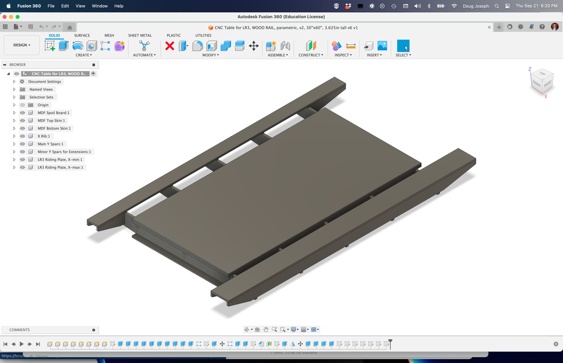
Thus, it is helpful to know that when mutiple copies of a body or component are being created in a linear array based on the location of the first one, you only have to re-move the first one. For the Y spars, the first one is on the left from the front.
Good job as always.
It’s probably possible using joints and ~magic~ but ain’t nobody got time for dat.
1 Like
Please note! The asymmetry of the LR3 and LR4 are not exactly the same. The table at the top of this thread was designed for the LR3. To get a sense of the actual asymmetry of the LR4, consider this post by Ryan of V1 Engineering, showing an affordable and doable way to get a full size table for an LR4: ~ $200 Full sized Lowrider table, Non-CNC Build
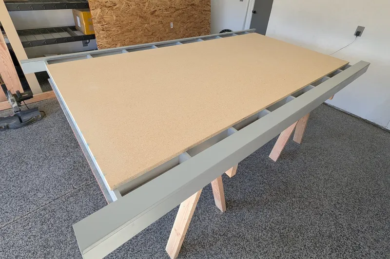
If you take his newer asymmetry in that newer table design, I think you will be happier.
My LR4 is still riding on a table that was designed for LR3, and thus its cuttable area is not centered perfectly, and thus not as usable as I’d like.
closing old topic to help fight spambots