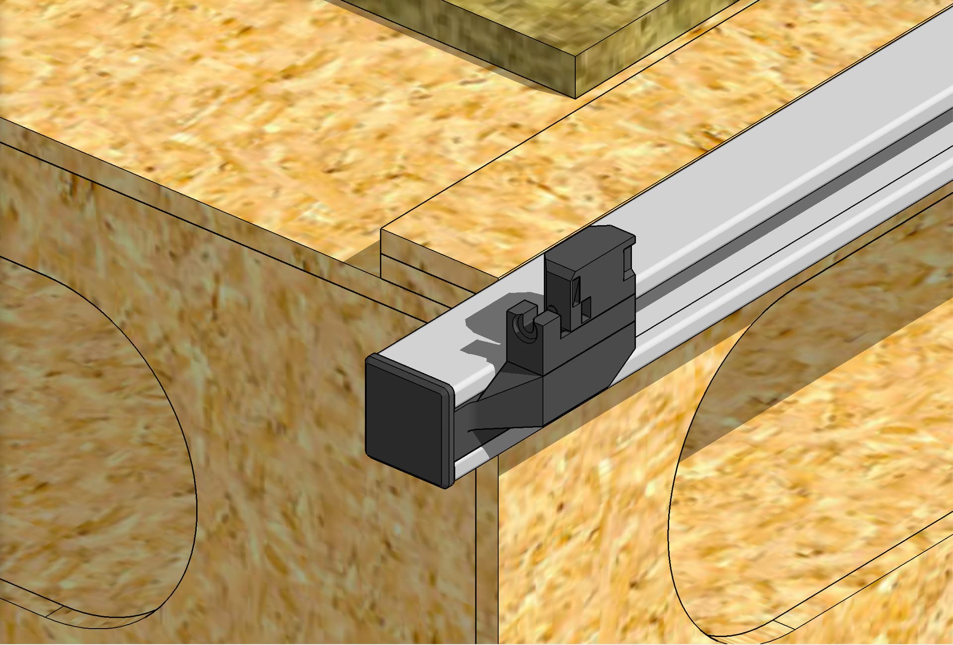
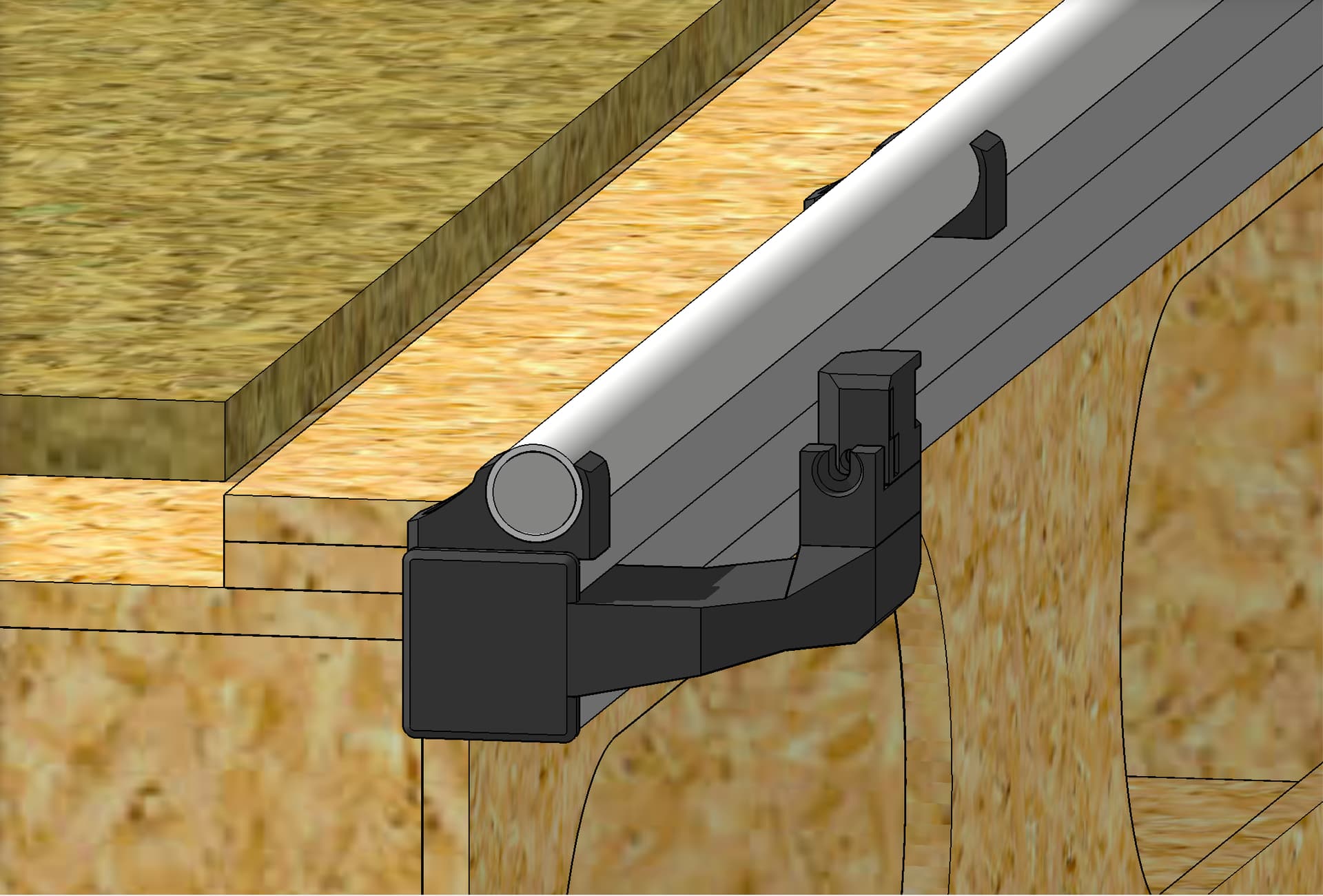
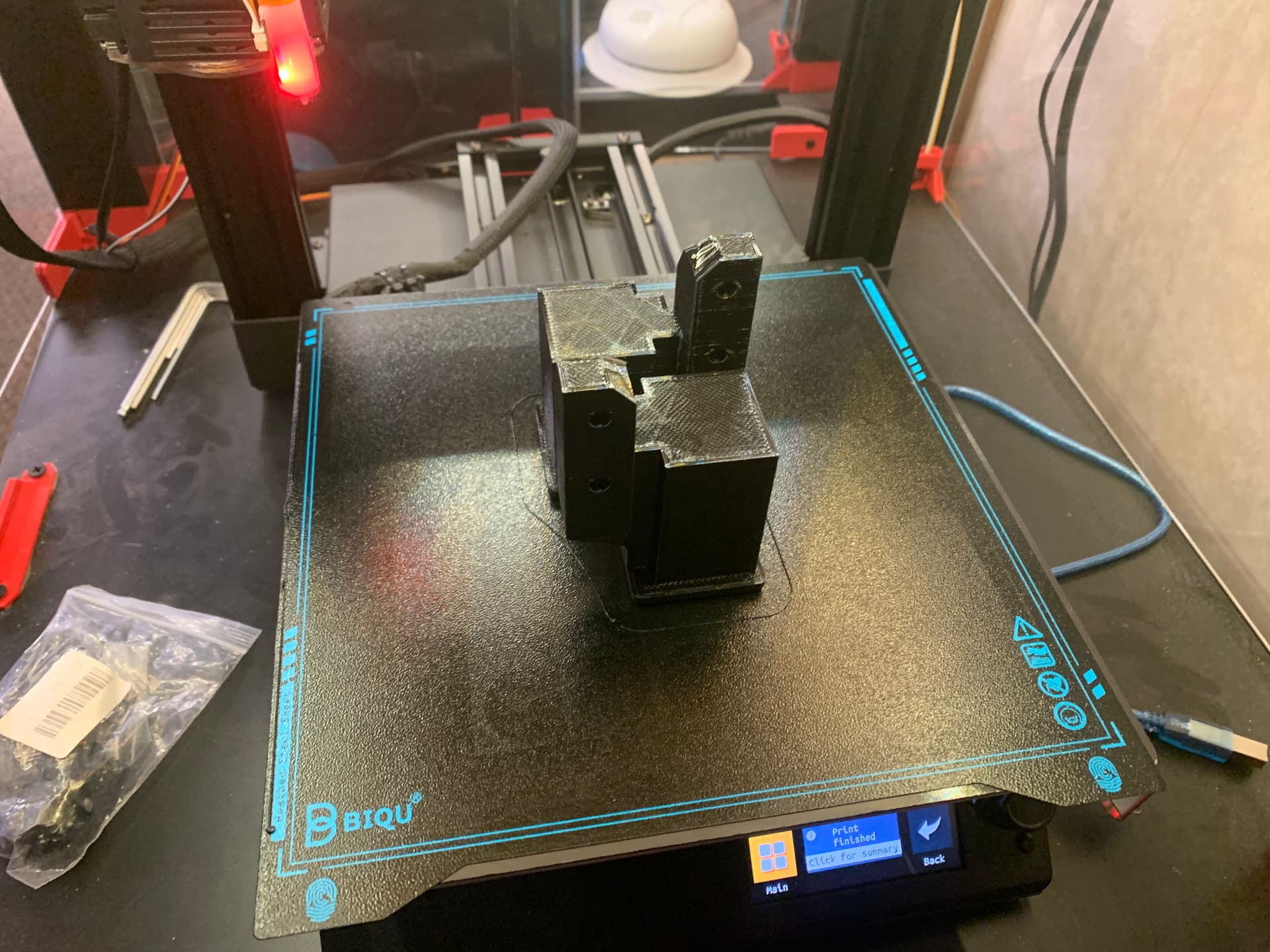
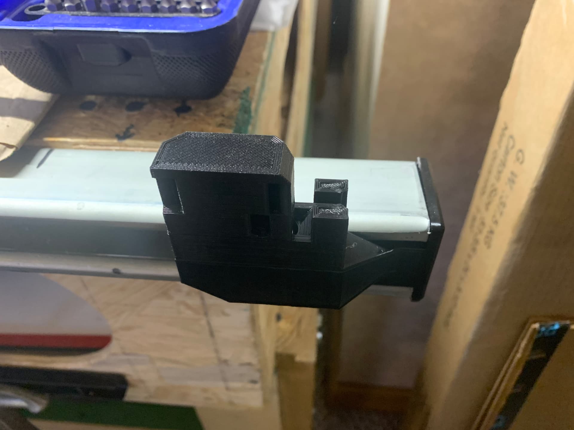
Here’s what I’m working on for “end caps” for my super strut metal rails, to hold the Y tensioners in position, without having to widen my table. The ones for the far side, where the Y rail is, will be similar but will need to jut out more. I’m printing a rough prototype now, of these (still modeling the far side). Open to input and suggestions.
1 Like
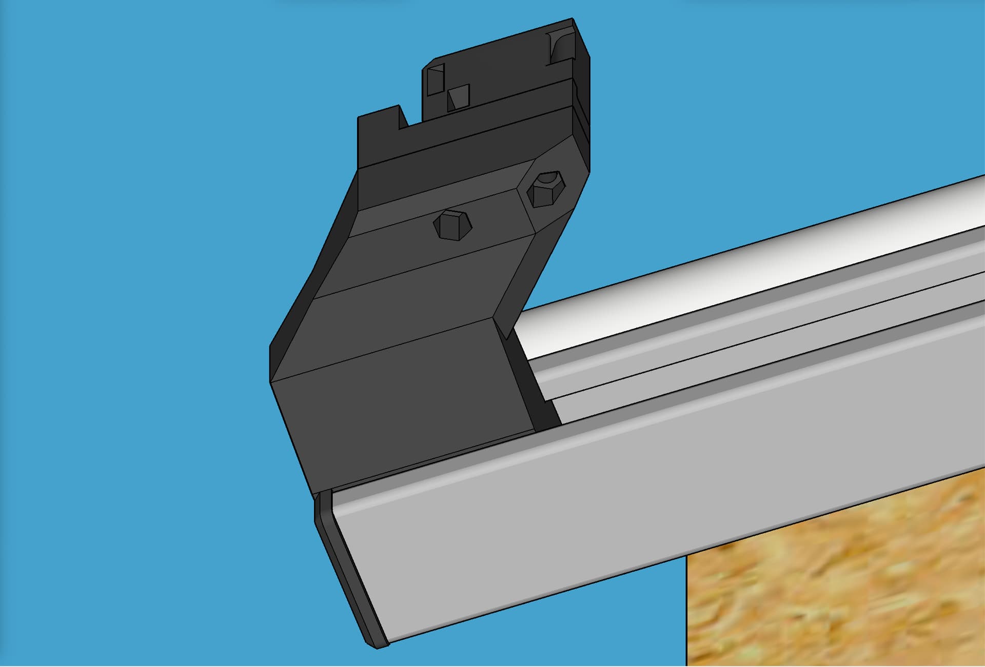
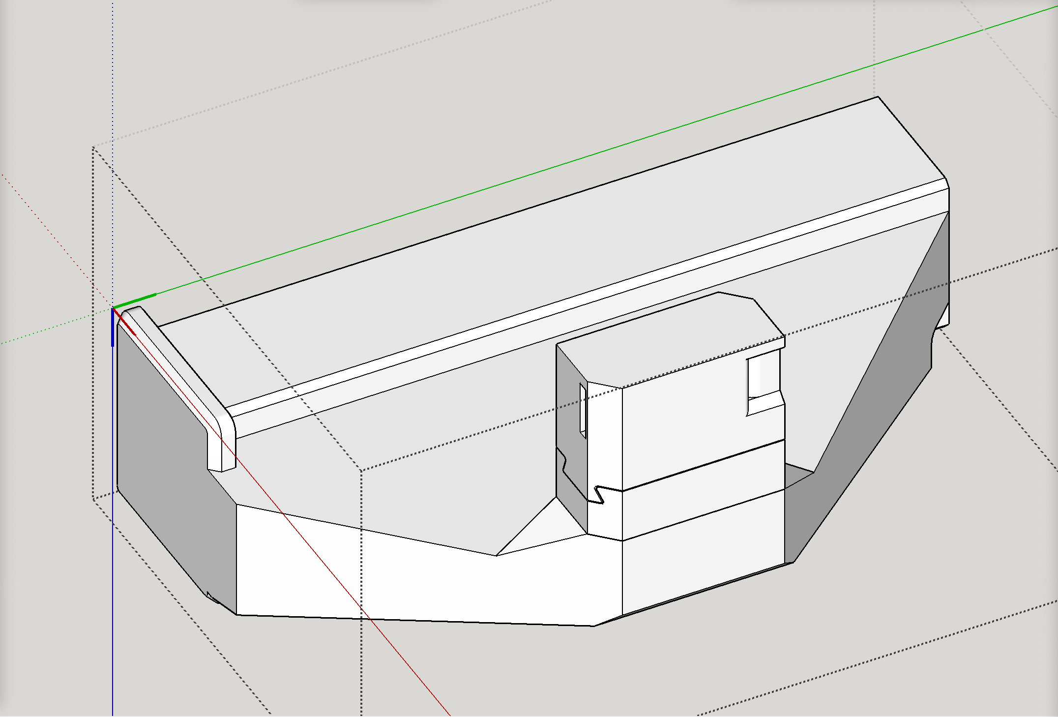
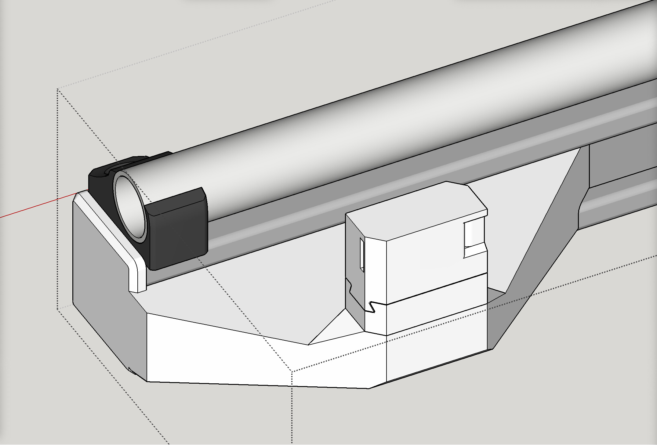
Here’s my current modeling for the far side “end caps” (side with the Y rail) for my super strut metal rails, to hold the Y tensioners in position, without having to widen my table.
These are under the machine and have a pretty significant load on them. Make them as thick as possible and I would add a brace in the direction of compression since that is stronger that printed parts in tension.
2 Likes
Thanks for the analysis and tip. Thanks in general for all the great help and advice!
I’m pondering on what you said here, and trying to understand it. I thought that the weight of the sides and center beam were resting on the wheels on the one side and on the rollers on the Y rail on the other side, and that the rubber belt itself is not load bearing (other than the tension that you mentioned is targeting around 6 to 7 pounds of load). In my scenario I would have the Y rail mounted firmly to the metal “super strut” which is very secure and very strong, and on the far side I would have the wheels riding on the metal super strut. Is there a weight of the sides and gantry pushing down on the rubber belt? Or were you just referring to the stress of the belt tension? I know that these plastic end caps can bear the load of the belt tension, because I’ve been using this type of set up with the LowRider 2 for quite some time.
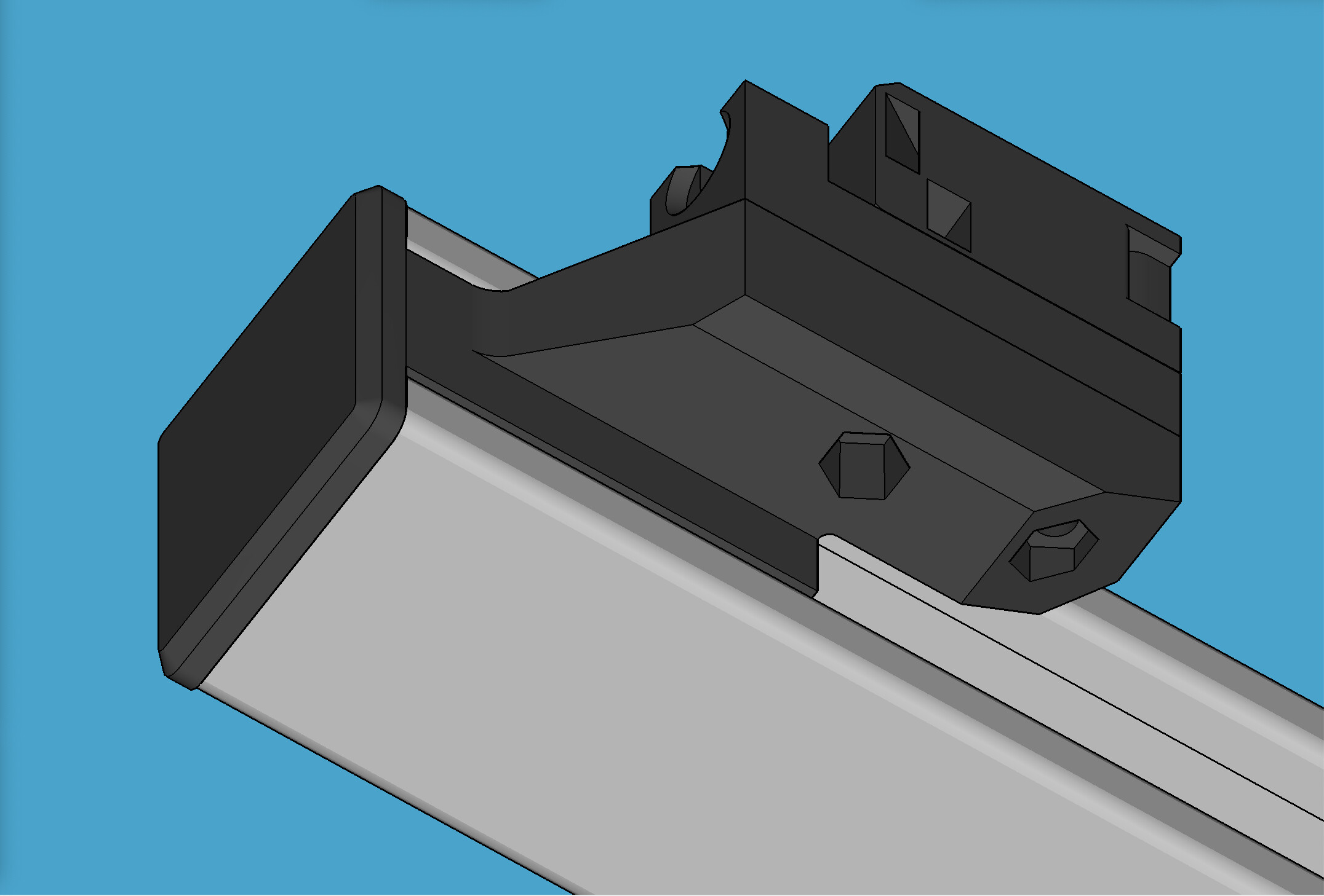
These are thin wall prototypes only used temporarily for test fit. The actual final items will be thick and strong. I’m glad to say that my modeling fit on the first try.


2 Likes
The tension on the belt, and the load from cutting and acceleration. There is just no reason to have it floating when you can add a brace. Maybe it isn’t needed, maybe it is. You have the parts give them a shot.
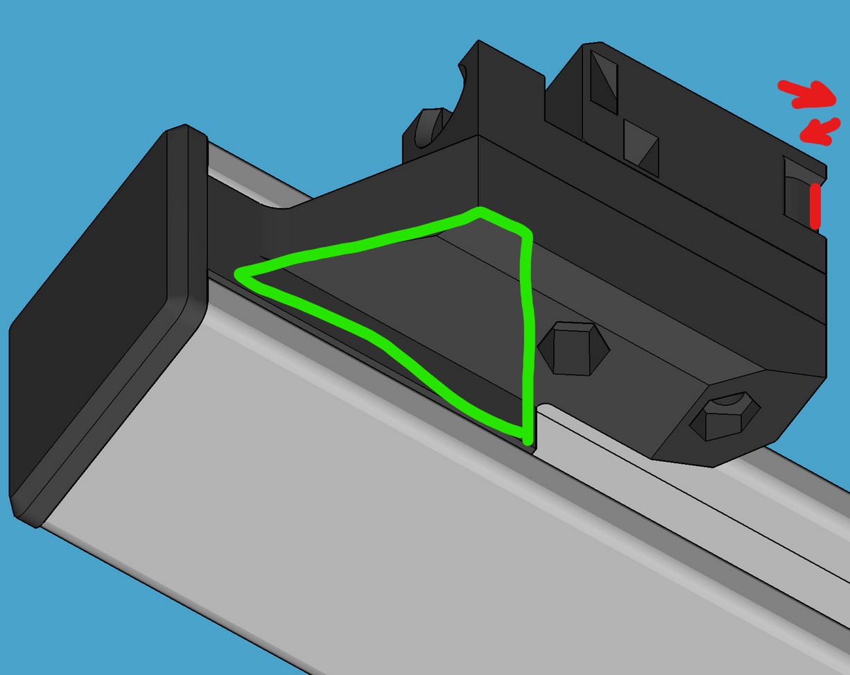

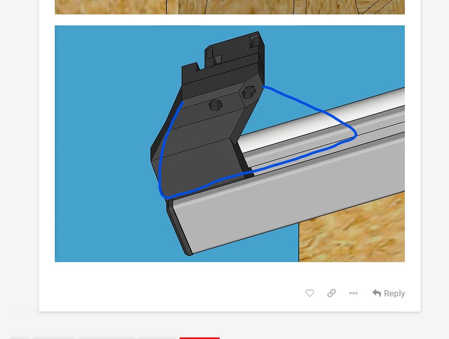
Load is in red. You are creating a lever arm, I am proposing getting rid of that. You can even leave mine open to reduce print time.
@vicious1
Got it! I felt like I designed them pretty strong, but you know better than me what kind of forces this new LowRider3 will bring to bear. It is very kind of you to use your engineering expertise to guide us non-engineers. I will take this to heart in looking at the design again.
1 Like
What did you mean by leaving yours open to reduce printing time?
Think he means his suggestion. Leave it an open “bridge” instead of making it solid.
2 Likes
Ah. Got it.
2 Likes
I can easily get rid of the lever by lengthening the inner core that runs inside the metal super strut. I could even do bridging with gaps to relocate the strength without increasing the print time or usage of plastic.
Adding a support arm structure outside it is doable but will require some careful measurements and pretty fine tolerances on print dimensions mentions, because it wouldn’t really serve as a brace if it was too far away from the super strut such that it didn’t make contact until the part broke. I’ve been able to get some pretty spot-on measurements and some pretty fine tolerances on the core inside the strut. It is literally touching the inside of the strut on all sides, and requires a little bit of pressure to slide it in. So I think I’m up for the task of designing a support arm that would span down on the outside as well.
1 Like
Those look sharp. I like the fact that they are going to line up exactly where you want them on the superstrut.
1 Like
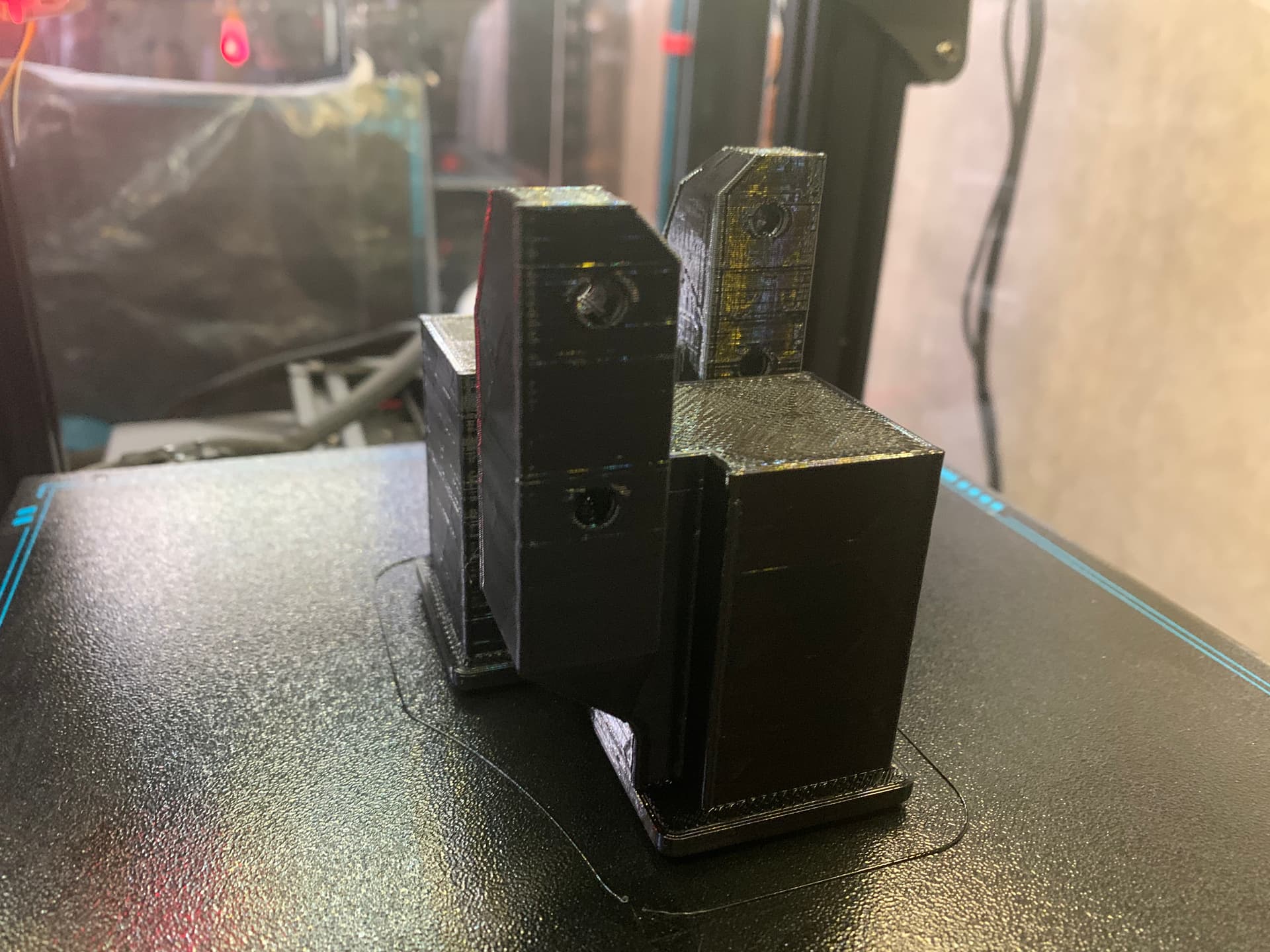
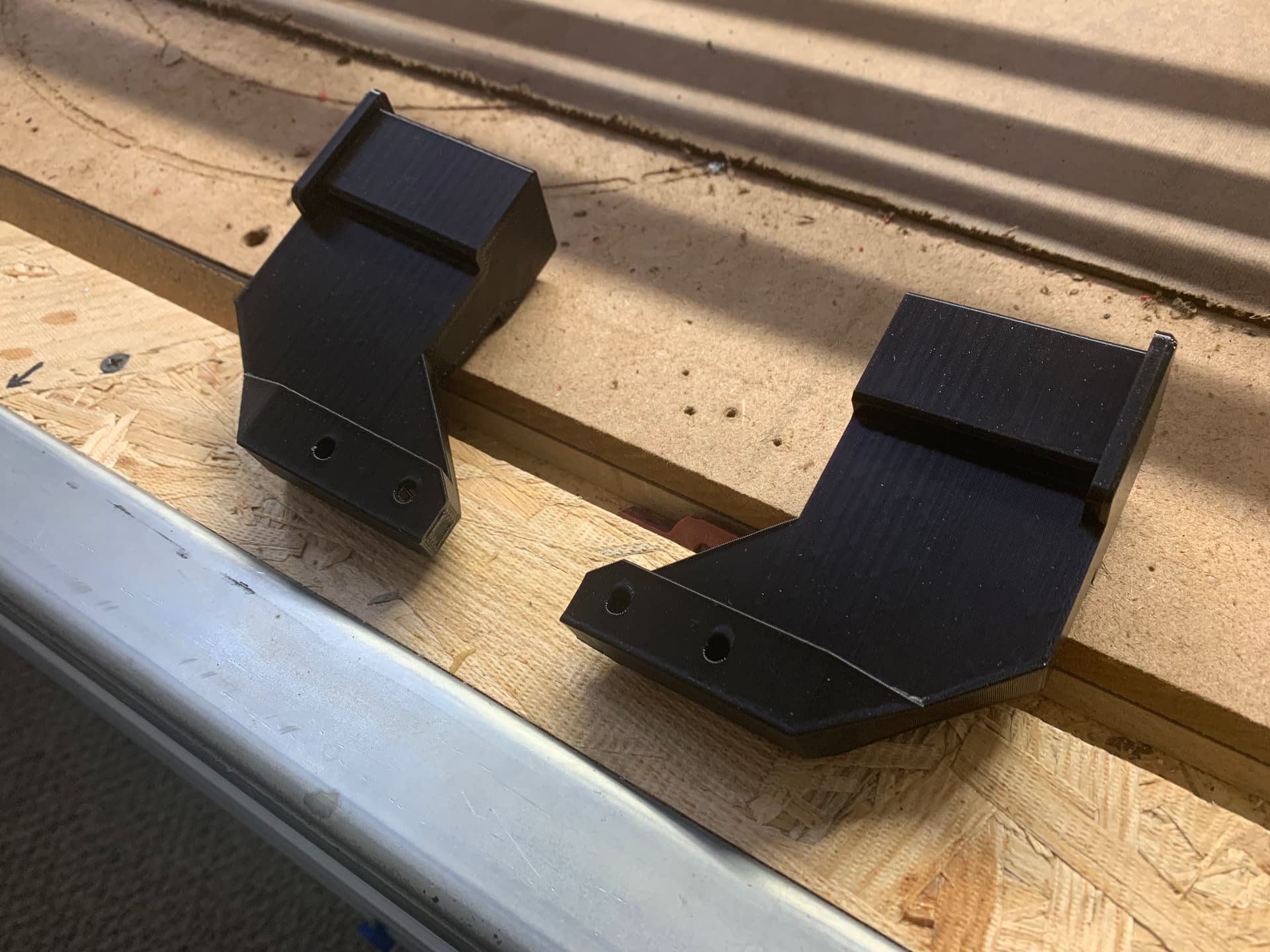
Before I got the helpful suggestions from Ryan, I already had a print job almost done on a thick-walled edition of the endcap/tensioner holders for the side with the Y rail. I’m going to go ahead and put them on, and see how they do, and if they break then I’ll have a good idea why. In the meantime I will probably work on improving the design, so that even if these do OK I can have an even better version for sharing.

1 Like
Those are nice looking parts. The problem is probably less “breaking” and more flexing. Since the belt tension will be pulling on these, they may have a propensity to flex under acceleration loads, which will result in inaccuracy with your cut. Adding the bracing will then put a compressive load on the printed parts, which is considerably stronger and less prone to flexing.
I’m sure that you will get acceptable results with the parts as-is, but I think that you’ll be happier with even a very slight improvement in accuracy that a stronger part will bring.
2 Likes
@SupraGuy
Excellent explanation. Thanks. You all have convinced me.
MORE VIDEO:
LowRider 3 MPCNC - lead screw alignment tips, X belt install tips, and more - May 31, 2022
NOTE: as of this moment, it is still uploading. When it becomes available, the link below should start working.

1 Like
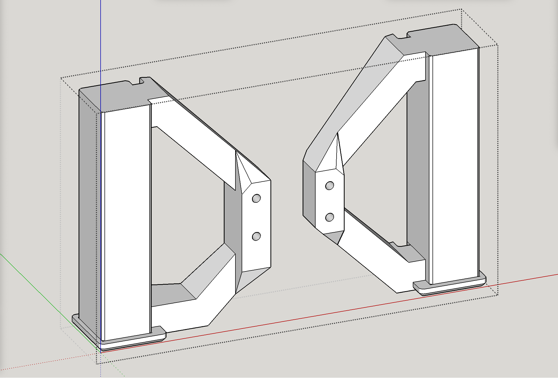
I have beefed up the “end cap” tensioner holders on the right side. (These are narrower than the left ones.)
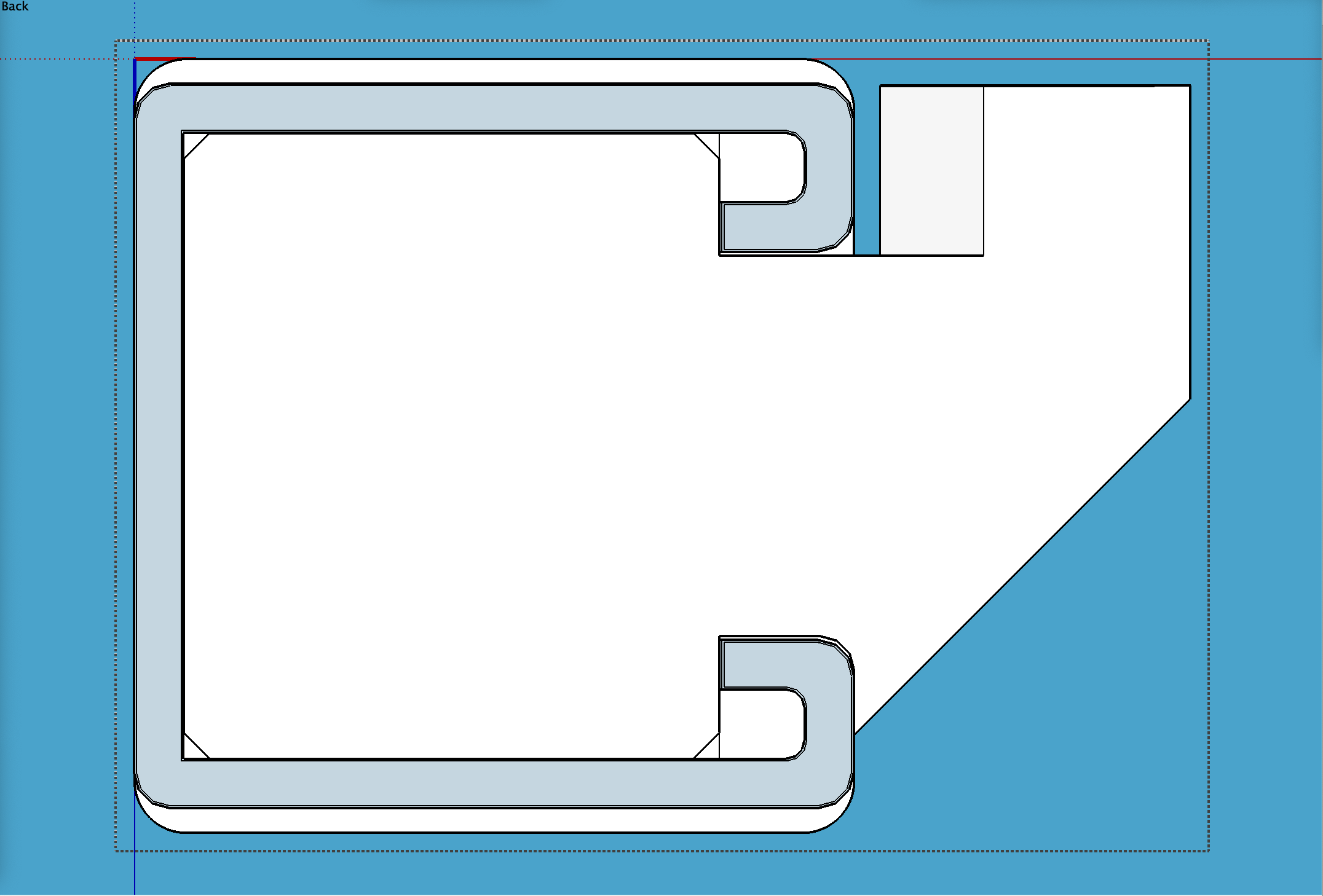
I decided not to worry about the increase of plastic and print time. Punching a hole in it down the core, would only cause new perimeter walls in trying to reduce infill, and I did not think it would have been worth it. In the screen shots below, the gray represents the profile of the metal strut. I added bracing angled downward, intended to ride on the outside of the metal strut. The risk here is the part being unable to fit. We will see! I am still working on the wider two on the left side.
Update 1: Just realized I did not extend the length enough, as I have not yet established the lateral bracing suggested by @vicious1 — More soon.
Update 2: OK, reworked it to add lateral bracing as well.
Right Rear:
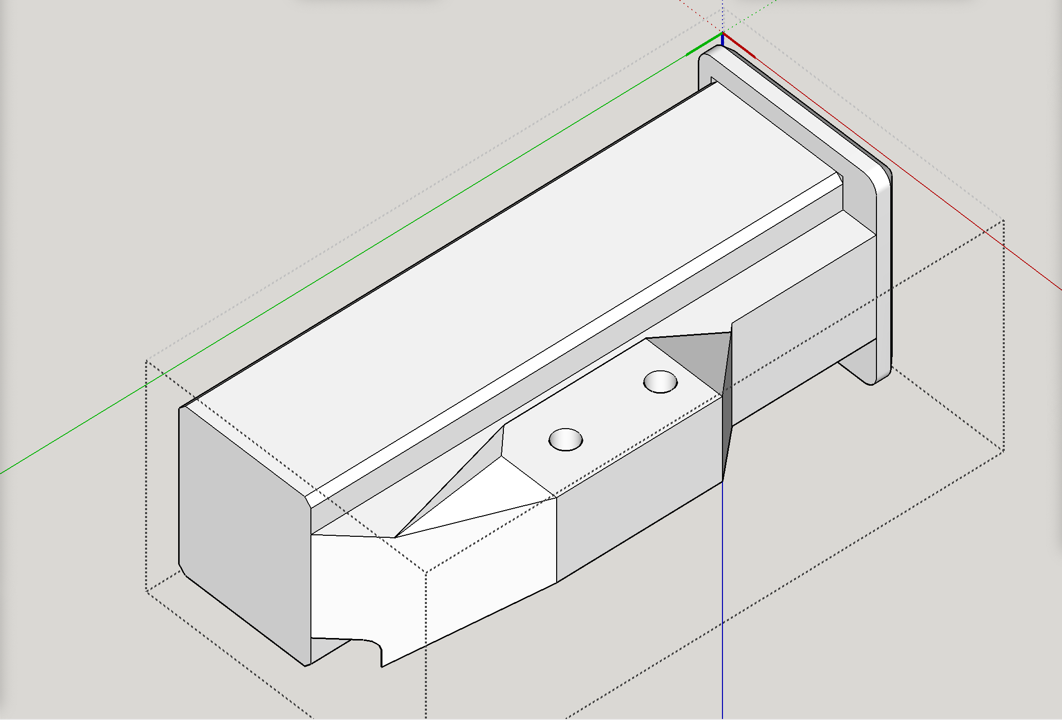

Right Front:


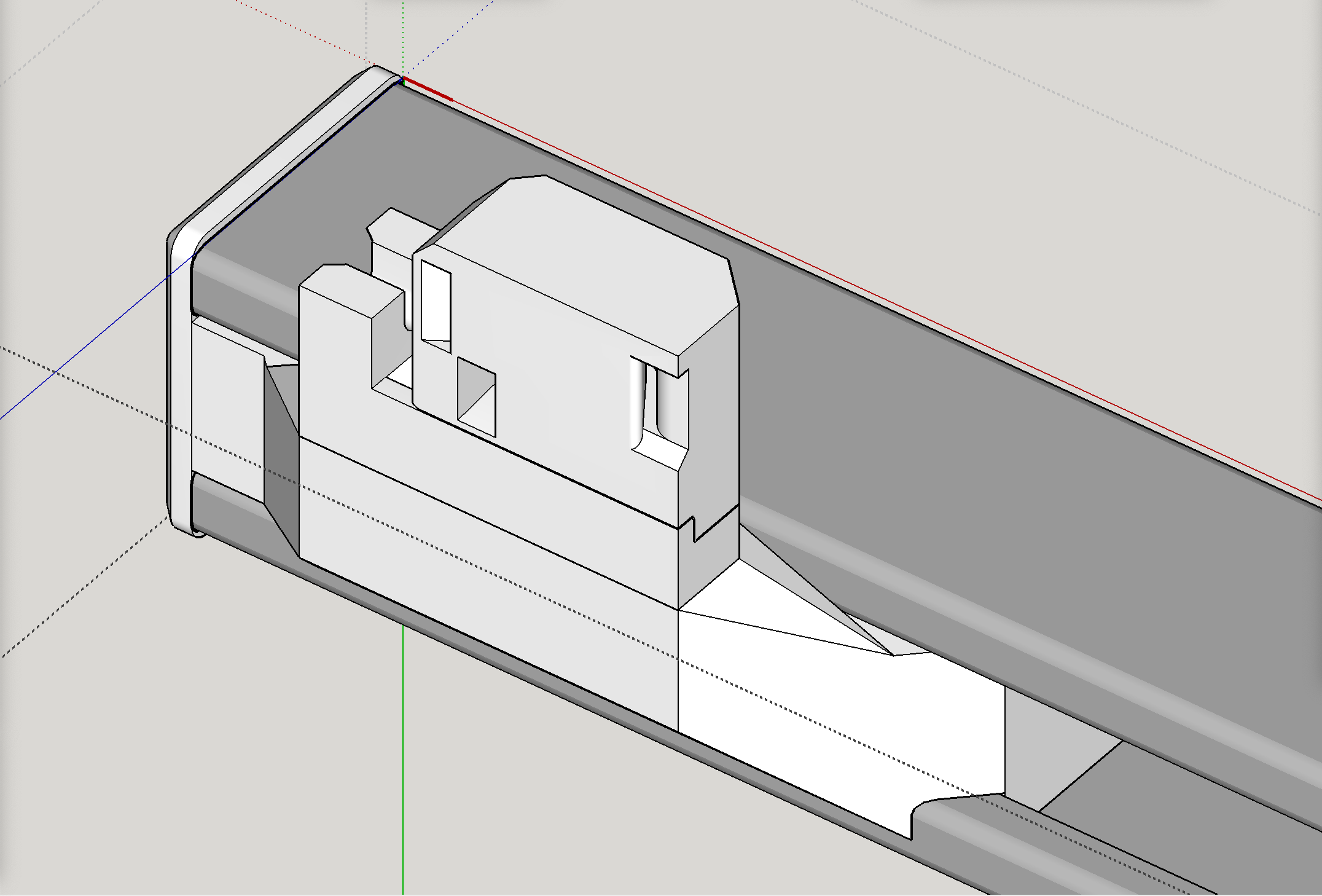
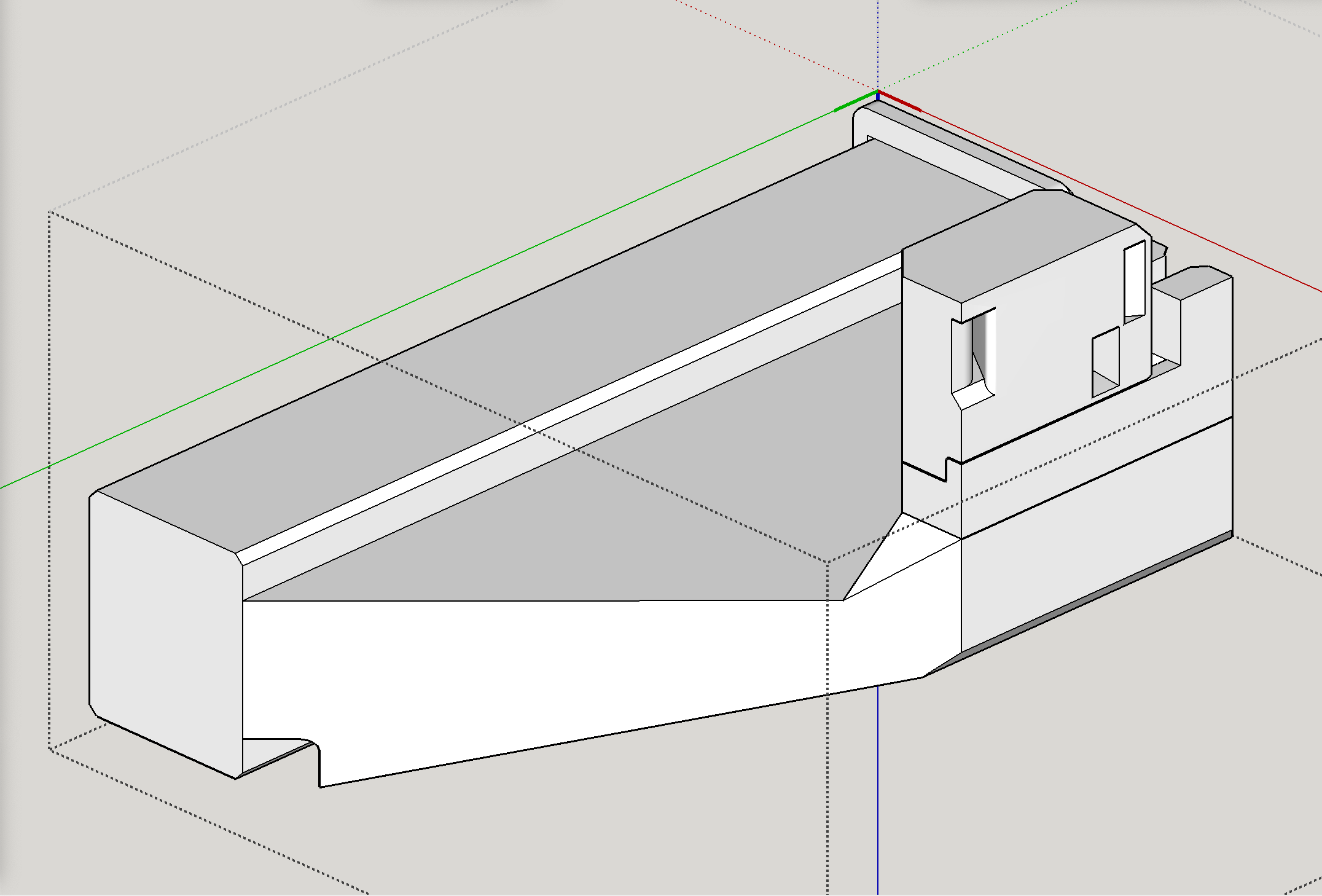
More work accomplished on beefing up the “end cap” tensioner holders on the left side. (These are wider than the right side ones.)
Update 1: Just realized I did not extend the length enough, as I have not yet established the lateral bracing suggested by @vicious1 — More soon.
Update 2: OK, reworked it to add lateral bracing as well.
Again, the gray represents the metal strut I’m using as a side rail on my table, dating back to LowRider 2 usage.
Front Left:


1 Like
I ran some slicer tests to calculate the cost (in time and grams of filament) both without any cutouts, with a cutout in hollowing the core (I was right earlier when I guessed that adding perimeter walls in the core would cost more than the saved infill), and by carving out hollow places in the “wings” (actual benefit there, the infill is reduced, and the perimeter walls were a mix of gain and loss, with an overall net gain). All these were based on 3 walls top, bottom, and sides, and 30% infill:
| Part | Original design: | New, no carve outs: | New, hollow core: | New, carved out wings: |
|---|---|---|---|---|
| Front LEFT and Rear LEFT | 6h 8m, 157g | 13h 19m, 367g | 16h 11m, 373g | 10h 42m, 268g |
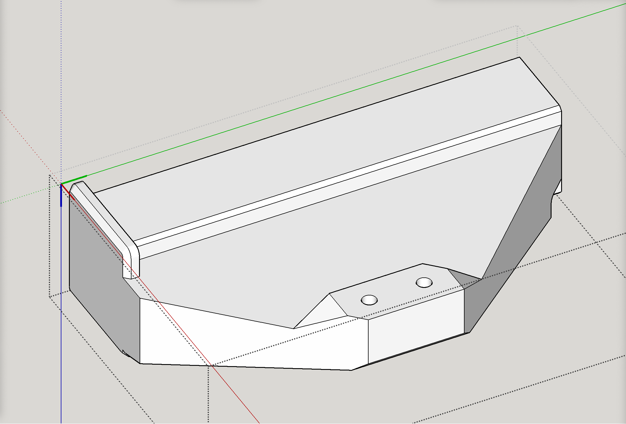
Based on this, there is a savings on using wings with holes (separated braces instead of a continuous brace). @vicious1 Ryan, if the “open wings” approach seems good, I will settle on that.
See screen shot below of the open wing approach: