Got all end stops soldered, wired in and attached. Checked the Z end stops for “click” before end of range of Z motion, and it’s not hitting the end stop first, and looks like the end stop would have to be right at 5mm lower to hit it first. I think that’s a little too much to just bend the metal stop. Probably looking at a remix of the printed part.
1 Like
That’s strange, unless you’re using significantly different switches, or have them oriented the wrong way, it should work out OK.
I’m using these ones:
https://www.amazon.ca/gp/product/B08736NP44
they seem to be working fine.
(Actually, might be these ones:)
https://www.amazon.ca/gp/product/B07DS9J3GD
but both work the same as far as I can tell.
I am using switches ordered from V1. I have them installed as shown in the pics in the docs.
EDIT:
Just realized where I went off script. I did not have 2.5mm screws, so I widened the holes a little. That seems to have added enough non-precision to affect things this way. I will find a fix. It’s worse on one of the Z’s than the other. No big deal. Gimme a a few minutes, will have it fixed.
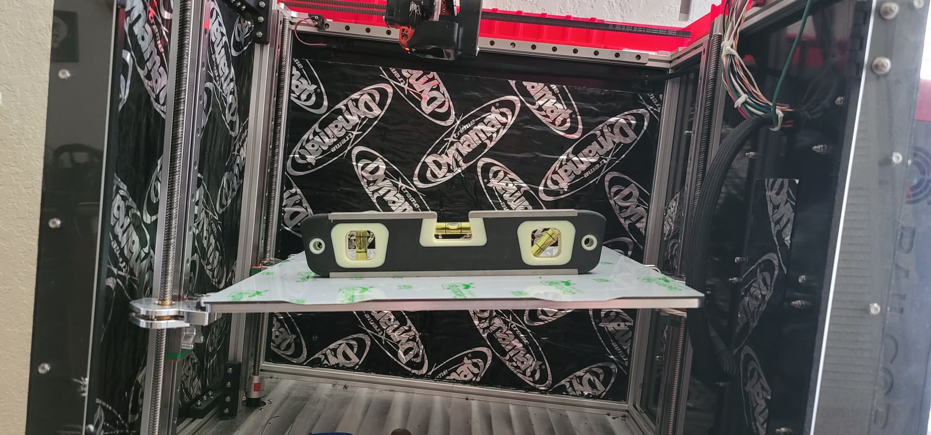
Okay, I can see that, but unless you’re using a machineists level, that plastic home depot level isn’t really accurate enough for the tiny variences we’re dealing with. Maybe I’m just being too picky. My printer auto trams to a minumum of .005mm across the bed. Then it bed meshes out any build surface imperfections.
I’ve just seen people try to “level” the bed with a level, and not the table the printer lives on first. That’s why I made this image.
5 Likes
I hear you. I used a digital level with a decent level of precision. Checked a “bubble” level before breaking out the digital one, and it was horrific.
1 Like
@barry99705
That image is hilarious!
And of course it is quite true that a bed trammed to its own printer’s frame can function perfectly at angles wildly different than level with the horizon. I’m just finding it helpful to use the horizon. I discovered my X bar was slanted down ever so slightly in comparison to the printer frame. The digital level helped me find that, but only because I had already struck readings on the table and printer base.
I have an app on my phone that does a bubble level, also has a digital readout of X and Y angles. I have used that for tramming, because it’s easy to compare.
2 Likes
If you have a probe, you can see the mesh values. That will tell you if you can adjust the overall tram. Or, if you want something more manual G30 will measure the height at any point you want.
@jeffeb3
I have a probe and can see the mesh values, but that cannot tell you whether your X axis bar is off, or whether your Z axis bars are not plumb.
1 Like
True. It depends on your printer, but if it isn’t square, the distance won’t help.
1 Like
LowRider 3 MPCNC - Beam Assembly (X-Gantry Structure) - first phase - tips - May 29, 2022
 - first phase - tips")
3 Likes
I don’t know about everyone else, but I run a file over the cut edges of my tubing, giving it a bit of a chamfer, also along the inside. The LR3 doesn’t have the same need for it as the LR2 did, to run wires through the tubing, but filing down the inside edges of the cut end as well doesn’t leave sharp edges that can cause injury hanging around.
Ryan has the CAD available for the strut plate as well, so that you can manipulate it a little more easily, and there are user contributions that are super easy to manipulate. Still the stretch of 1400mm to 1425.4mm is a pretty small percentage so it shouldn’t cause a problem.
I keep thinking I should read the instructions, but on the Beta builds, we didn’t have them. I don’t know if it’s mentioned, but I found it very helpful to install the captive nuts and the screws for the 3rd plate first, before assembling the beam. That’s when I had the best reach for the captive nuts. It was also easier to install the rest of the 5mm screws and nuts loosely with the beam unassembled, again, because it was easier to reach the nuts with a wrench. This is particularly true if your 5mm holes are a little tight on the screws.
2 Likes
Yeah I have it set to install all the screws and nuts on the beam before it even gets built. We had it a lot harder.
2 Likes
I filed down the burr on the leading edge of the cut on the conduit, which as you know in the case of a tube cutter, the leading edge is the protruding inside diameter of the conduit. It did not occur to me that there is a slight ridge created when the tube cutter pushes the metal out to the sides. That ridge is on the outside diameter of the conduit, and that was what was biting into the plastic, I think. I could have filed it down if I had thought about it. But I didn’t think about it.
That’s what I used. ![]()
That’s another good tip. It’s easy to comprehend these tips in hindsight after you’ve put it together without knowing what you were doing the first time!
2 Likes
20/20 hindsight is definitely a thing. I did all this with my second beam build…
1 Like
LOL. I heard that!
Since we beta guys were building without instructions (and I still have not read any of the build instructions), I just “popped” my tubes straight into the braces. I didn’t slide them on at all. They didn’t seem to suffer any ill effects.
2 Likes
Yeah I doubt they will just want to, make sure the instructions were “more correct”.
1 Like