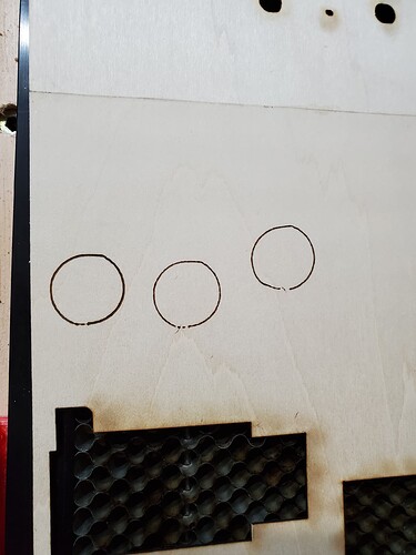
I have an old MPCNC I made over 8 yrs ago - still has the Ramps 1.4 board - it’s worked fine for years. I put an LED 40w laser on it and that has worked fine. I did a project a few weeks ago that had a number of holes (circle cutouts) and they came out perfectly round. I didn’t measure the square cuts, but, they had to accurate as everything fit together perfectly. But, yesterday I cut holes and notices they were not round. The X and Y square cuts look fine. All of a sudden it doesn’t make round circles. I’ve attached photo.
The circles are made with laser at lower power so it just drew the circle in 1 pass. It’s no longer round - comes almost to a point on one side and there are gaps where it started and ended. 2 of the circles in the photo represent different programs to generate the Gcode, and 2 different programs sending the file to the cnc - so it is Not on the software - gcode or PC side. The Gcode is sending a long serious of X Y moves (not the arc short hand commands). Something happened with the CNC.
I swapped the X and Y Stepper drivers on the CNC (the build uses separate drivers on 2X and 2Y motors - and I swapped all 4 driver). A 3rd circle is after swapping - same. So, it isn’t the stepper drivers.
(one of circles is darker because I ran the code 2 times without moving the board - otherwise all ran exactly the same - all of them not right).
I’m asking for help in how to troubleshoot. Could the MEGA2560 card have problems that could do this? (I was going to swap out the control board at some point, but, since it still worked, there really was no reason). Could one of the steppers be a problem. It isn’t erratic, as I drew more than those 3 circles at various sizes and positions on the table and they all look exactly the same.
The unit worked fine just last week, not used it since. But, now the circles are off. But the square X Y look fine. I will put a rectangle at 45 deg angle and see how that cuts. Any advice on how to troubleshoot is appreciated
