Offsets and Bit Setter

Looking to make some changes in Marlin to “offset” (if that’s what I should be doing) correctly and incorporate the a bit setter (Shared it in the FB group).

  1. I want to make sure Z is up as far as possible before homing to avoid destroying end mills, stock and the bit setter. While testing, I have seen the Z go up so far it jumps off the Z rod and then skip. I assume this is because I don’t have the height and or offsets set correctly but I was wondering if this could hurt anything. If it’s not possible to prevent the rod from coming off, and it won’t hurt anything for it to skip, I assume it could be okay to have the Z reattach to the rod with just the weight of the tool. If not, please let me know what I need to do for best case to make sure Z is not crashing.

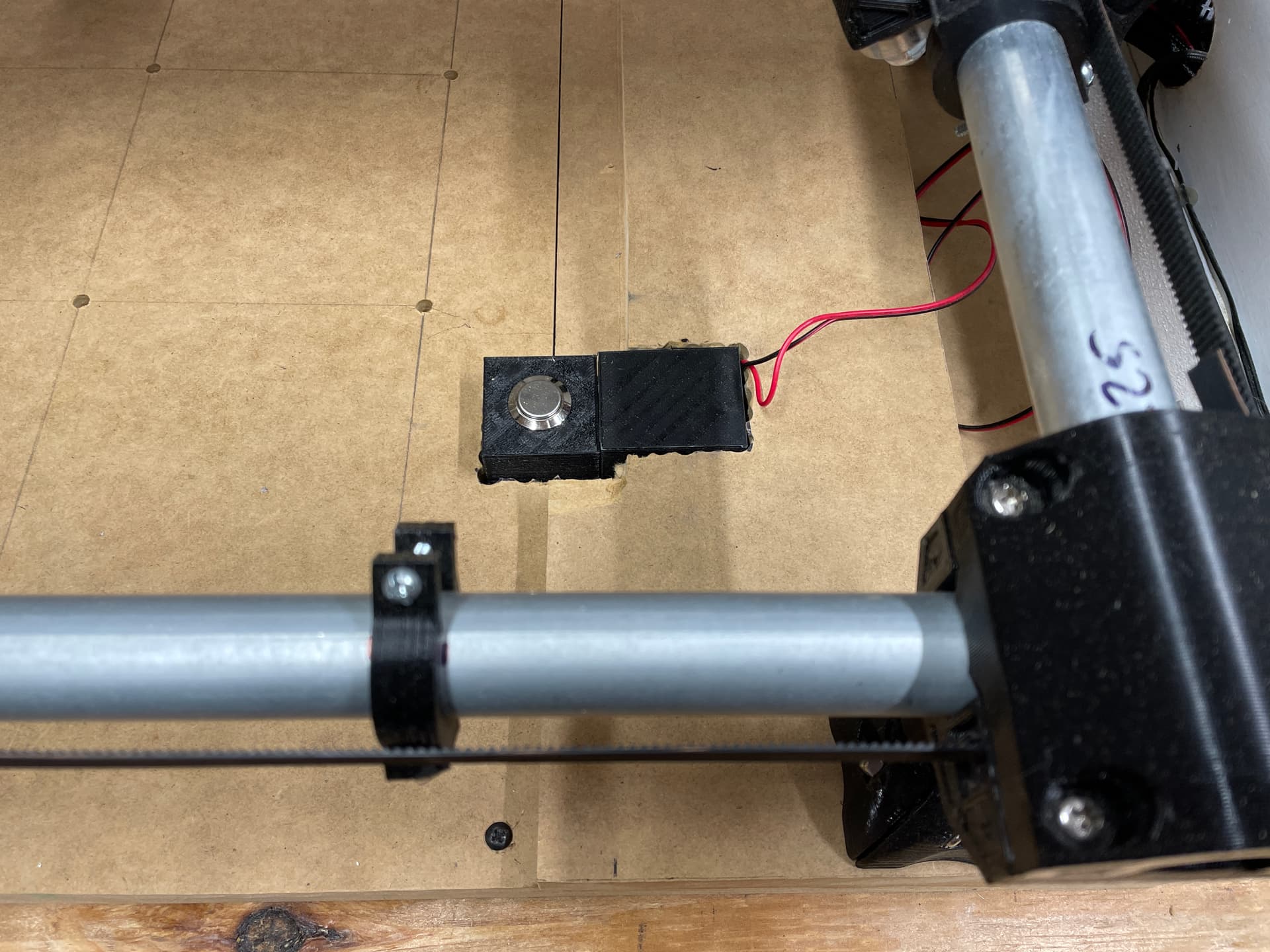
  2. Here is a photo of the front right corner. the bit setter is placed at X/Y Zero so I would like Z to raise, X/Y to home, Z to probe and then for the starting point to move no less than 30 mm on X/Y (to avoid the bit setter) before starting any cutting.

  • I am hoping there is a way to set the firmware so I will not lose 30 mm across all of X and Y, but just the small square of the front/right corner (where the bit setter is.).

  • Should I be enabling a probe setting in Marlin to enable the bit setter? If so, I suspect there might be code there that will have consideration for what I would like to do regarding not starting the tool in this 30x30 space.


Thank you all again for your help.

The only possible damage to the Z would be the coupler between the leadscrew and the Z motor shaft. Skipping steps doesn’t hurt the machine.

You’re definitely into the advanced setups for the CNC. These are some things you should look into:

A) The low rider firmware homes up and enables the Z probe and G38. G38.2 Z0 will probe down and G28 Z will home up to the Zmax endstop.

B) There is a CNC workspace workspace gcodes. You can switch between machine coordinates (measured off of the endstops) and workspace coordinates (for cutting). For example, what you could do is:

  • Home X Y Z up
  • Do your machine set up, jog the machine where you want XY start.
  • Switch to workspace coordinates and force X,Y=0
  • Probe to the surface of your work, set workspace Z=0
  • Do your cut.
  • Switch to machine setup and jog to the max. Then jog to your bit setter.
  • Probe down to touch the bit to the top of the bit setter.
  • Move up 100mm or something.
  • switch your bit
  • probe down again (but then, this number needs to be used somehow)
  • jog back to Z max
  • switch to workspace coords
  • move to X,Y=0
  • continue

That feels like a lot. But if it is well tuned and automated, it might be pretty slick.

The more common way to do that is to just probe the top of the workpiece after a tool change. That isn’t always possible, but it usually is.

3 Likes

I am starting to understand more about how the MPCNC is intended to be used after reading one of your old replies “Endstops aren’t needed on a cnc machine. The location of zero is critical, but it is not determined by the machine boundaries, it is determined by the workpiece boundaries. (The reason we use dual endstops is to square the machine, not set the origin).”

In my case, I want to set the machine up to protect it as much as possible from crashing and breaking bits. I added a Z Max endstop. I assume “USE_ZMAX_PLUG” needs to be uncommented and also found “Z_HOME_DIR 1” in Marlin but, I cant find where Z homes before X/Y so I need to find that setting. (EDIT: changing these settings homes Z first)

I don’t have any issue with jogging to a workpiece so no need for the G38’s but I will be looking into what the workspace feature.

It looks like the only Issues I have left are…

  1. Z can continue to be moved up after the limit switch is toggled.
  2. Not sure how to probe the bitsetter (now that Z homes up) or what I need to change to have it correctly measure its position based on the tool and height of the bitsetter.

Jeff, Thanks for all your help, I know this is pretty involved and appreciate the time you spend helping everyone here.

1 Like

A few thoughts:

  • “Crashing” your machine into its limits is largely non-destructive. It makes an ugly noise, but that noise is the stepper losing steps, not any sort of physical damage. And I’ve never broken a bit in any situation where I’ve hit max or min of the machine. The worst thing I’ve done is break a stop block and had to 3D print a new one.
  • You can write custom g-code for the homing sequence. As far as I know, there is no specific “bit setter” solution in Marlin, so will need to write the g-code to make it work.
  • Homing up and probing (G38) down is the setup for the dual endstop LowRider, so you could take a look at that configuration.h and configuration_adv.h files for the V1’s Marlin version for that machine.
  • Workspaces (G54-G59.3) allows you to set an offset for your work while preserving the machine offset. Using workspaces will be required for your scenarios since setting a home position in the machine “workspace” results in the firmware losing any sense of home or the other machine limits. They will also be required if you want to use your bit setter in an automatic way.

Based on the forum, 99.99% of MPCNC users ignore all of what you are trying to do and cut in the “machine” coordinates relative to the stock.

Question: Did you get your bit setter from Carbide 3D, or is there someplace else that sells them?

1 Like
  • Almost positive there is a probe function for the Bitsetter.
  • G38 is throwing me off as it discusses target probing. IE workpiece not work area.
  • I’m having trouble wrapping my head around workspaces and offsets, still have to research them more or see a video to better understand thanks.
  • I’ll likely “cut in” as well… I’m thinking a scenario where the owner of the machine is not running it such as an employee that cost more in bits than salary.
  • I made the Bitsetter myself and released it5 in the FB group for all to use to give something back to our community. You can find it here (Bit Setter Universal by shapeandraise - Thingiverse).

Thank you for your help

  • Almost positive there is a probe function for the Bitsetter.

Probing is the same no matter what the device. There is no specific bit setter routine like the bit setter on the Shapeoko. The Z axis moves down (or up) until the circuit it is looking for is triggered. In all the scenarios I can envision for your setup, you would probe in world (machine) coordinates using the bit setter, then you might probe again (using a touch plate) in the workspace coordinates for your job. Both can use the same wiring/circuit, though the g-code you execute for the probing itself will be different.

  • I’m having trouble wrapping my head around workspaces and offsets, still have to research them more or see a video to better understand thanks.

You can think of workspaces as “remembered offsets from the machine origin.” When that workspace is active, anything you do is relative to that offset. Say you place your router at 100,100 in machine coordinates and switch to another workspace. If you then execute a “G92 X0 Y0” to set the current position to 0,0 in that workspace, all g-code will consider that point the origin of the job. If your g-code then executes a “G1 X10 Y10” to move to 10, 10, you will be moving to 110, 110 in machine coordinates. If you then execute a G53 to return to machine coordinates, your machine now knows it is really at 110,110.

  • I’ll likely “cut in” as well… I’m thinking a scenario where the owner of the machine is not running it such as an employee that cost more in bits than salary.

Marlin, the firmware that V1 maintains for the MPCNC, is open-source 3D printer software that was later adapted for CNC use. Features that you might find on a firmware that was originally designed for a CNC (like GRBL) might not be in Marlin, or might not perform as well in the Marlin firmware. There are MPCN owners running GRBL, and some of them are active on the forum.

I made the Bitsetter myself…

Cool! I might use your files and build one for myself. My only concern is the accuracy of the switch. For some kinds of MPCNC cutting (like v-bit carving), being off by 0.5mm can really make a difference in the results. You might run some tests once you have things up and running.

Edit to add: 99.99% of all MPCNC users simply set their machine coordinates to the origin of the job/workpiece. In doing so, they lose all sense of the real machine’s origin and limits, and the firmware no longer considers itself “homed.” In general, the steppers are not powerful enough to do any real damage, so they can get away with this simplified solution.

I recently switched to the RepRapFirmware for my CNC machine and I LOVE IT for CNC work. It has the ability to use “GCODE anywhere” and “macros”. Translation = 99.99% of the things you would need to modify in the marlin firmware, recompile and flash the control board for can be done with GCode commands and macro files. If you want to reprogram the way the probe feature works just tweak the macro file or have two macro files that each probe a different way.

I’ll give you one small example of a Macro I wrote for my machine. It is a “Level Z axes” macro. It will save the current location. Then display some buttons that will allow me to Jog just the Z axes. I can move the axes close to the top or bottom limits. Then click ok. Then it reduces the power to the Z Stepper motors by 70%. Then shows the same buttons that I can use to Crash the Z axes against the physical limits. That makes them aligned physically without causing any damage. Then I click ok and it can ask me if I want to return to the saved location or cancel.

My Home Z macro is similar. It will display the Z jog buttons then when I click OK it will call G92 Z0. But I can have another Z probe macro that will automatically home Z using a touch plate or probe. Same machine with two different options using different macros.

EDIT: And the RRF can be loaded onto several SKR control boards. So you don’t have buy the name brand DUET control boards if you don’t want to.

2 Likes

The Marlin developers used grbl and Sprinter firmwares as starting points, and then pulled out stuff that didn’t seem to serve 3D printing (like multiple coordinate systems) while adding in stuff that did (like temperature controls and thermal runaway protection). I find it very interesting that a lot of what was stripped out is getting added back in as Marlin is moving from the 3D printing space back into “traditional” CNC usage.

Most of these settings are in or around the Homing and Bounds section of config.h - check here for documentation.

To keep the Z axis from driving up off the screw/nut, you’ll need to set Max Z travel in config.h. What you set it to depends on your specific machine’s physical setup. Think of the “bed size” as your desired work envelope, than add movement outside that space if your machine allows it. For example, when my 3D printer’s X axis triggers the end stop the extruder nozzle is about 3 mm to the left of the edge of my heated bed and it can move about 7 mm to the right of the bed before it hits the frame, so I’ve got X set up to allow travel from -3 to +207, but with an X Bed Size of 200. Noting gets printed off the bed, but the nozzle can move anywhere within that envelope. On my Burly, I’ve got a Max Z switch that is already at the top of where the machine can move, so my Z _Home_Dir is set to 1, and my Z_Max_Position is this height measured from the top of my spoil board.

Marlin distinguishes between Homing operations (G28) and Probing operations (G38.2-G38.5). With your bitsetter connected to the proper “end stop” plug on the control board, and defined as the probe connection, you should be able to specify the X and Y coordinates of the bitsetter and the speed (rate) at which you want the probe to descend in a G38.2 command (assuming you want an error generated if the probe doesn’t get triggered).

I have tried to figure out how to use a probe or bitsetter to compensate for tool length when changing tools, and I could not come up with a solution that works purely with gcode that doesn’t need an external calculation or something.

To get specific, suppose you are cutting a relief and you touch off the roughing tool against the top of the workpiece. After the roughing pass there is no longer a top surface available. You change to a finishing tool which is not the same length, and now you want a finishing pass.

You could probe G38.2 off the bed (or fixed probe device) and M114 to record the coordinates before removing the roughing tool. Then with the finishing tool probe G38.2 again and M114 to get the coordinates for the other tool. Then calculate the difference and some G92 can align the finishing tool to the roughing tool.

But unless you can save the locations as variables and use those variables in subsequent gcode commands, I don’t think it is possible to automate it within the gcode, and it would require external hand calculation or maybe an OctoPrint plugin to automate.

I think I tried it, but I will have to try again, using homing (G28) on something like the bitsetter and then setting a work offset (G54+G92) on the top of the workpiece. I think homing again (in machine coordinates) with the finishing tool did not adjust the G54 workspace accordingly, but ideally it would. I will try that again, because that would be a solution if it worked.

1 Like

I’m also in the RepRap Firmware camp, so I’m less familiar with how Marlin does things, but in RRF, “homing” always sets machine position, not workspace. I use a different operation to set the workspace offset as compared to the machine position. This lets me keep using the soft stops in firmware to prevent the Gcode from ordering a plunge more than 2.5mm into my spoilboard, so I never have to worry about the machine hitting T nuts (Primo) or track (LR) for my holddowns.

2 Likes

I had a vague memory of offsets ‘not working correctly’ but I tried it in more detail, and it looks like it is possible.

G28 will set machine coordinates, and the offsets relative to machine coordinates are preserved. But there is a bug that requires that you switch coordinates. With a workaround, it looks like it is usable.

Here is what I did:

  • Home the machine, G28 Z
  • Move to Z=+10
  • Switch to “workspace 1” with G55
  • Set workspace zero with G92 Z0

Now, if you switch back to machine coordinates with G53 and home G28 Z at a different physical height, it will show Z=0 at the new physical ‘zero’ height. Now switching to workspace 1 with G55, and M114 shows Z=-10 because the workspace has the origin set 10 mm above the machine origin. All is good.

But here’s the bug: if you home G28 Z while you are in workspace 1 (G55), then this happens:

  • Suppose you’ve set up offsets as above, and you’re already in workspace 1 with G55
  • Home Z with G28 Z
  • After homing, M114 shows Z=0 (wrong)
  • Make sure you’re still in workspace 1 by doing G55 again
  • M114 still shows Z=0 (wrong)
  • Switch to machine coordinates with G53
  • M114 still shows Z=0 (correct)
  • Switch BACK to workspace 1 with G55
  • Now M114 shows Z=-10 (correct)

I think a long time ago I had observed some part of this behavior and thrown up my hands and given up thinking that homing resets offsets. I think a simple rule would work as a workaround, which is:

Always switch to machine coordinates (M53) when homing.

Technically this is stricter than necessary to get the offsets to work properly, but as a minimum you have to switch out of a workspace and back in, and this is an easy rule to remember.

If we assume a bitsetter is just a fixed probe spot that’s triggered by the tip of the bit, then the workflow is nice and easy. Suppose you want an easy tool change:

  1. Switch to machine coordinates (G53) if not already
  2. Home X and Y
  3. Move X/Y to the known location of the bitsetter
  4. Home Z
  5. Switch to your workspace coordinates with G54
  6. Jog to your workpiece
  7. Probe with G38.2 or use a piece of paper (or your favorite method) to set the bit to the workpiece
  8. Set workspace coordinates with G92 X0 Y0 Z0
  9. Perform operations with first tool
  10. Switch back to machine coordinates G53
  11. Move to a location handy for switching tools, high enough and near the front
  12. Switch to second tool
  13. Move X/Y to the known location of the bitsetter
  14. Home Z
  15. Switch to workspace coordinates with G54
  16. Continue job with second tool (should raise to clearance plane)
  17. Repeat from step 10 for as many tools as your job contains

By keeping G53 X/Y in machine coordinates, the location of the bitsetter is in a fixed, known location. The workpiece location can be arbitrary and G92 within the workspace offsets allows the job to operate relative to zero being the corner of the stock, which is more convenient than having to model the stock location within CAM.

Now I need to build myself one of those.

3 Likes

Wow, this is a lot of info, I’ll can print and ship you the parts for the bit-setter if you want, but you may want to download the files to add more strength to it.

To clarify, I am only looking to probe Z-Min to make sure the length of the bit is considered and precise. I am using a fixed position for where all stock will be placed so hopefully that decreases the complexity here. I am using the Guffy1234 post processor in Fusion360 but can add custom start Gcode in Octoprint.

In the meantime, I’ll try to wrap my head around everything discussed above.

Okay all, I think I originally added some confusion to my post by using incorrect terms such as offset.

Here is what I want to do…
Move Z to home (up out of the way first)
Home X and Y
Probe the bit setter (to prevent the bit from running into the spoil board)
Move Z to its highest position
Move X and Y to the workpieces zero
Lower Z to the workpieces zero
start the spindle (smartplug)
start the dust collector (smartplug)
Reset the coordinates to 0 / I think I need to do this Fusion360 to start properly.

So I believe I need this…

G28 Z X Y / Home
G38.2 Z0 / Probe Z-min
G0 Z81 / Move Z all the way up
G0 Xxx Yxx / Move X and Y to the starting point of the stock
G0 Zxx
M80 192.168.1.1 / start the spindle
M80 192.168.1.2 / start the dust collector
G92 X0 Y0 Z0

Any reason I am incorrect? Looks like “G38.2 Z0” will probe to the bit setter but I don’t see where in Marlin to set the height of the bit setter. Any reason I still need to change the coordinate system as previously discussed? I am not planning on doing tool changes till I can at least get some work started and even then don’t know I need to complicate that process beyond what I believe I may already have.

As always, thank you for your help but also sorry for the confusion.

G28 Z X Y / Home

You don’t want ‘Z’ in this command, or you want to mount your bit setter the machine’s home position, use this command, and remove the G38.2.

G38.2 Z0 / Probe Z-min

For the Primo, usually G28 Z is used for a touch plate, and that should work for your bit setter as well. I’ve not used G38, but from reading on the forum, it does not do a retest and therefore may not be as accurate. Note it is extremely likely that the trigger point for your bit setter and the top of your spoil board will be at different heights. It may make sense to set the Z height to the top of the spoil board here. Say there the bit setter was 5.2 higher than your spoil board. You could do a G92 Z5.2. At this point, Z0 would just kiss the spoil board.

G0 Xxx Yxx / Move X and Y to the starting point of the stock

How do you know what the two xx values are here? This would work if you had fences and these values were the corner of the two fences. It is not unusual for me to use the center of stock as my starting point, or to mount my stock at different places on the spoil board.

G0 Zxx

How do you know xx here? If you set Z to the top of the spoil board, then you can use the thickness of your stock in your CAD/CAM to calculate this value, but you will have to edit this value into your files somehow, since it will differ depending on the thickness of the stock.

G92 X0 Y0 Z0

As long as you define Z0 as the top of the stock, this will work, but there are times you may want to use the spoil board as the home Z position. If so, this line will not work.


I don’t think I’ve explained things very well here. Just think through the different scenarios. Your steps above only cover one specific scenario.

  • When cutting completely through my stock, like in contour cutting, I like to use the spoil board as my reference, but for other cutting (v carving for example), setting the top of the stock as the origin is critical.
  • I mount my stock in different places on my spoil board. Sometimes my stock even hangs over the edge of my spoil board.
  • I sometimes use the center of the stock as my origin rather than the lower left corner.

As long as your Z homes upward, I think your approach will work, except that G38.2 Z0 just leaves the tool at the height that triggers the bit setter, and doesn’t set any coordinates, as you observed. I would suggest G92 after G38.2, to temporarily save the length of the bit, and then another G92 after you move to your stock.

So to start with:

G28 Z X Y / Home
G38.2 Z0 / Probe Z-min
G92 Z<bitsetter height>

After this, coordinates describe the location of the tip of the bit (where Z0 = spoil board).

Note that you can no longer move to Z = 81 because it will crash into the upper limit of your Z range.
So instead, it’s probably better to move just above your stock, assuming you know the thickness:

G0 Z<xx + 5>  ; Move 5mm above top of stock
G0 Xxx Yxx ; Move X and Y to the starting point of the stock
G92 X0 Y0 Z5

At this point the tip of the bit is 5mm above the corner of the stock and “G92 X0 Y0 Z5” tells the machine that the current location is 5mm above the corner of the zero coordinate.

Then run the rest of the job.

M80 192.168.1.1 / start the spindle
M80 192.168.1.2 / start the dust collector
etc...

If you have fixtures that define your stock position then you can incorporate those coordinates into the gcode and the workspaces are not necessary. Even if you switch tools, you could run your procedure from the start for the second tool and everything would work fine.

The workspace coordinates G55/G53 etc. become necessary when the location of the workpiece is not known in advance, and you manually jog to the workpiece or probe its location. With a single tool, the location of the workpiece can be “remembered” in G92 coordinates and there is no issue. But when switching to a different tool with a potentially different length, moving to the known X/Y location of the bitsetter is nontrivial, and adjusting the Z height will tend to “forget” the workpiece coordinates unless you use the workspace offsets with the G55/G53 commands.

1 Like

I guess I should have gone back and reread the earlier posts if the G38 is for homing upward. If the G38 is to get max Z, then I would just remove it. When he homes downward to a known height (bit setter), he knows the max Z from that reference point.

Confused on this. What is the point of Probing if it is not factoring the distance to the probe and the height of the probe? Should I be probing some other way? I thought probing would take a fast and slow measurement so I am not sure G38 is a command I want to use if it is not probing twice and then saving that calculation.

Thank you!

I think there are two questions here, why doesn’t it probe twice for higher accuracy and why doesn’t it save.

The G38.2 is more of an ‘elementary’ operation that can be used in combination with other operations for a more complete solution. For example probing three sides of a circle to identify the center and radius of a hole, or if you want to locate the top surface and you want to do it 5 mm away from the left edge, you can first find the left edge and then move (using relative movement) 5mm over to probe Z. In our case we’re doing something similar to homing but G38.2 is useful for more than that.

As for probing twice, there is an option to do that in the firmware. It’s called MULTIPLE_PROBING in Configuration.h and it is disabled by default.

1 Like

Assuming your bit setter is using the Z min pin on your board, G28 will do what you want without firmware modifications, but there will be a difference between the trigger height and the height of the spoil board. And even if you somehow got the two to be equal, that would only last until you need to surface or replace your spoil board. So, you will want to do a G92 to compensate regardless of whether you use a G38 or a G28. Using either method to probe, the difference will be a fixed, known amount that you can put in your g-code.