I was wrong here. Part of the slower speed on quick layers is also ramping the fan to 100%.
Nice. Let me know how it works for you, or if you have any issues.
1 Like
From the Configuration.h for Marlin, it says the following:
/**
- PID Bed Heating
- If this option is enabled set PID constants below.
- If this option is disabled, bang-bang will be used and BED_LIMIT_SWITCHING will enable hysteresis.
- The PID frequency will be the same as the extruder PWM.
- If PID_dT is the default, and correct for the hardware/configuration, that means 7.689Hz,
- which is fine for driving a square wave into a resistive load and does not significantly
- impact FET heating. This also works fine on a Fotek SSR-10DA Solid State Relay into a 250W
- heater. If your configuration is significantly different than this and you don’t understand
- the issues involved, don’t use bed PID until someone else verifies that your hardware works.
- @section bed temp
*/
Does anyone know if a 750w AC heatbed going through an Inkbird 40A SSR will have issues with this?
The SSR looks like the same form factor as my SSR. I think I should be ok.
1 Like
I have a 1kw a/c bed heater at 240V with a 40A SSR operating using PID and its fine. It does not need a heat sink. Its on a 400 x400 bed that typically runs at 80 degC.
2 Likes
Trying out a big print. BTW, this is a really stupid design and is really inefficient. But it’ll get the job done.
It’s a right angle jig for the mpcnc so I can line up panels for cutting parts for the printw.
3 Likes
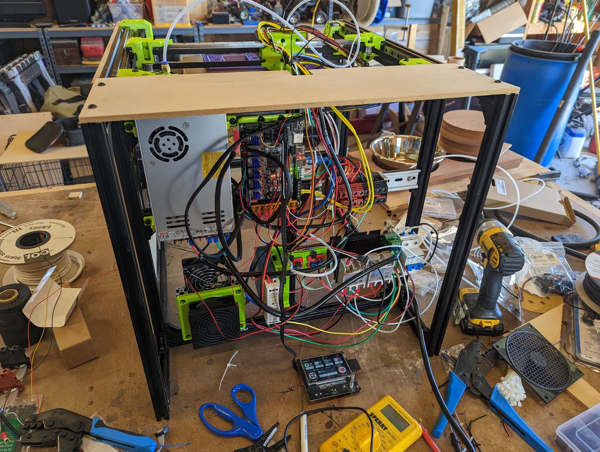
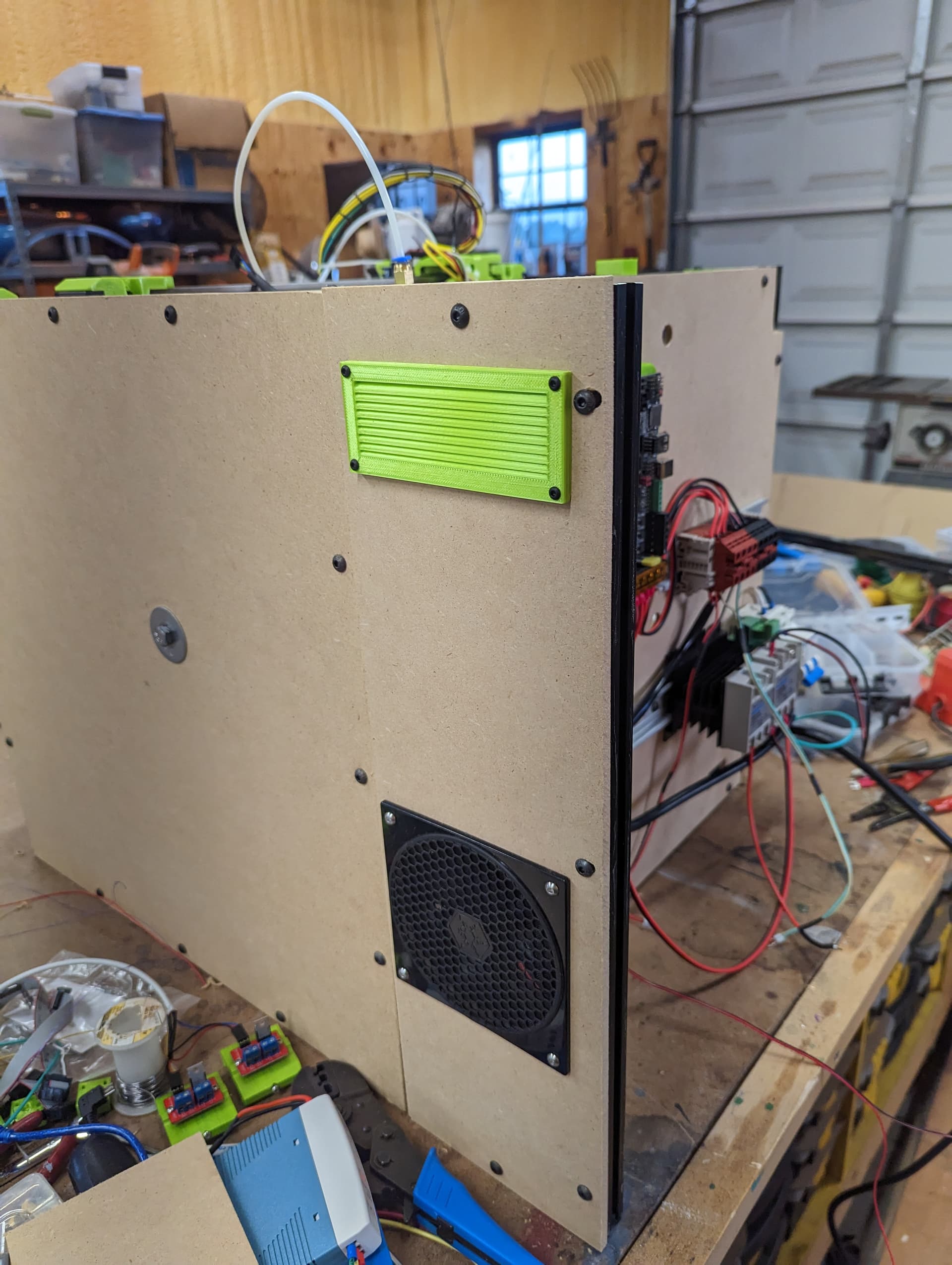
Started building the electronics enclosure while the part is still printing.
Sadly, I’ll have to take this all off to mount the back panel. I think it’ll slide off after only removing 4 screws
1 Like
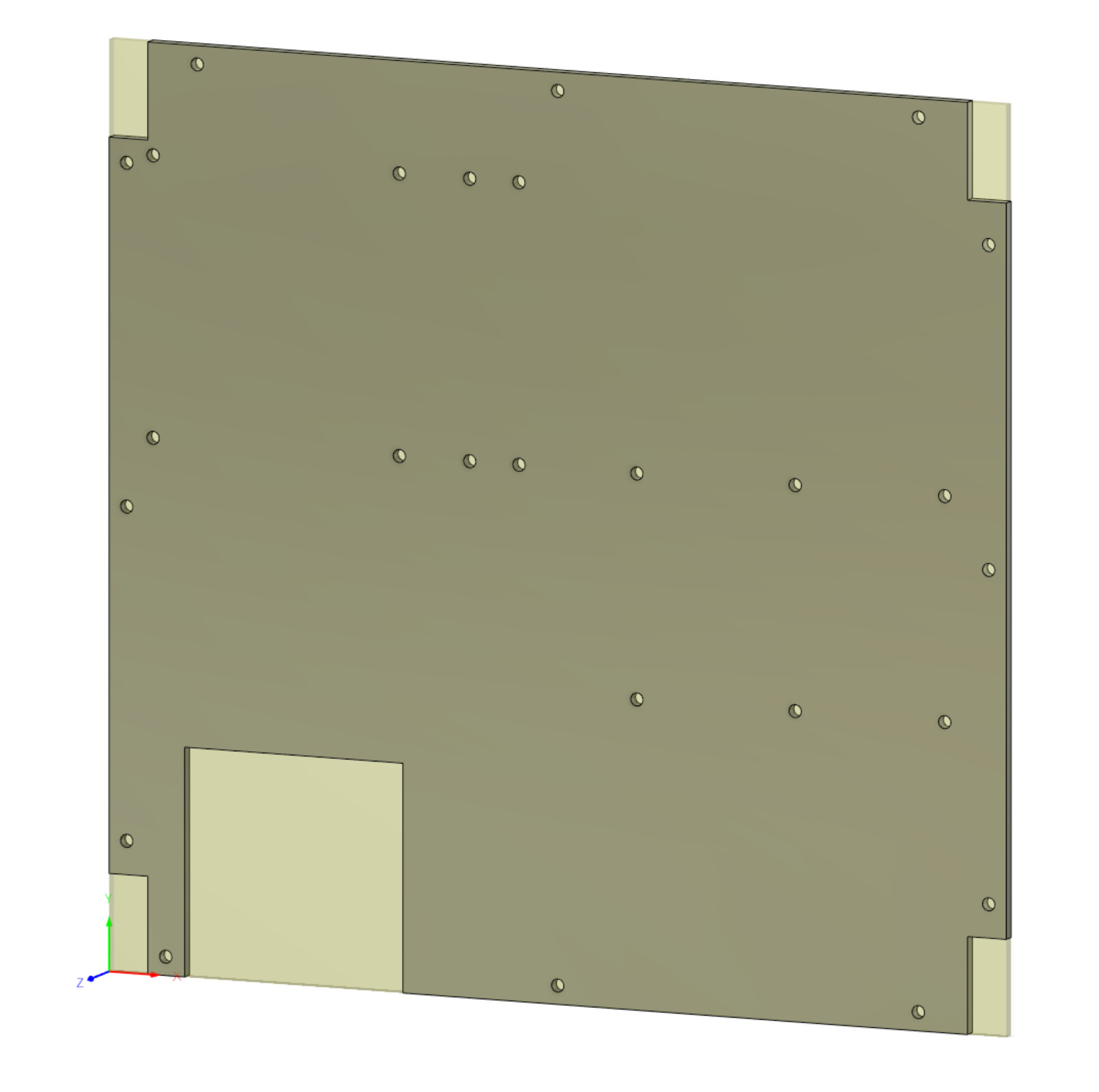
Taking bets on how accurate I have the holes placed on this for all the electronic stuff. I hope to try to cut it out tomorrow night.
1 Like
You’re braver than me. I gave up trying to figure out exact location for everything, ended up using DIN rail attached to Alu extrusion using Voron mounts. Voron Trident repo and Voron 2.4 repo have DIN mounts for everything, including LRS-350-24 and misc Controller boards.
The 6 holes on the right are for the din rails to mount to the extrusion.
The 8 holes on the left were taken from where the PS and controller are currently mounted.
I’m glad I’m talking about this. I just realized I forgot to put the holes for the cables to go through. There’s 4 holes missing.
I’m noticing on big prints that I’m still getting squishing on one corner.
What/how do I take advantage of the bed mesh so that that doesn’t happen?
For me that happened on the old build when I had wires bunching in that area.
It means somehow the probe is slightly lifting in that corner. It takes a critical eye sometimes. Power down and move the X rail front to back and see if your frame is moving at the top. Like wider and skinnier. Make sure the reverse bowden and wires are not bunching or pulling.
Also check to make sure your screws are tight from the centerpiece to the bearing block.
The other thing that can happen is the Y blocks can hit the corner pieces and mess with things if the belts pull really hard. If that is the case move your Y endstop out.
1 Like
Neither of my builds do that, but with the Y offset of the BLtouch, it doesnt take much angle to equate to 0.1mm (which is huge with 0.2mm first layer.
I set up the V4 for a bit of squish on the first layer because I still have trouble getting PLA to stick. I have gone back to blue tape… I have a flat machined plane 9" square that I sat on the magnetic bed. It could be taped down if you don’t have the magnets. It is guaranteed flat to within 0.001" (0.0254mm) that is still possibly detectable, but with a machinist straight edge, I think it’s well within 0.01mm at room temperature.
Anyway, I ran a 7×7 mesh level on it a couple of times, and made adjustments to the wiring harness and PTFE tube suspension until the result looked flat. The Repeat was actually easier to get flat response than the V4, I think because the larger build allows the tension to be more consistent? Maybe the longer cable exerts less force? Anyway, for the V4, I have the cabling suspended with a couple rubber bands from the closet bar which results in a perfect flat visualization. (Flat, but not perfectly level, the tool plate is heavy and the bed levelling didn’t like the tiny moves.) It wanted to think the tool plate lifted in the rear left until I suspended the cable
It could be belts bunching. My wire umbilical bends towards the back left corner of the printer where the print squished. It could be pushing forward on the z gantry as it gets to that corner.
I need to figure out some other way of attaching the wires between the gantry and the back rail.
LOL, rewiring and shuffling everything around, you’re not alone.
Am pretty much doing the same, also just finished 2nd attempt of cutting a bottom panel to help square up extrusion.
1 Like
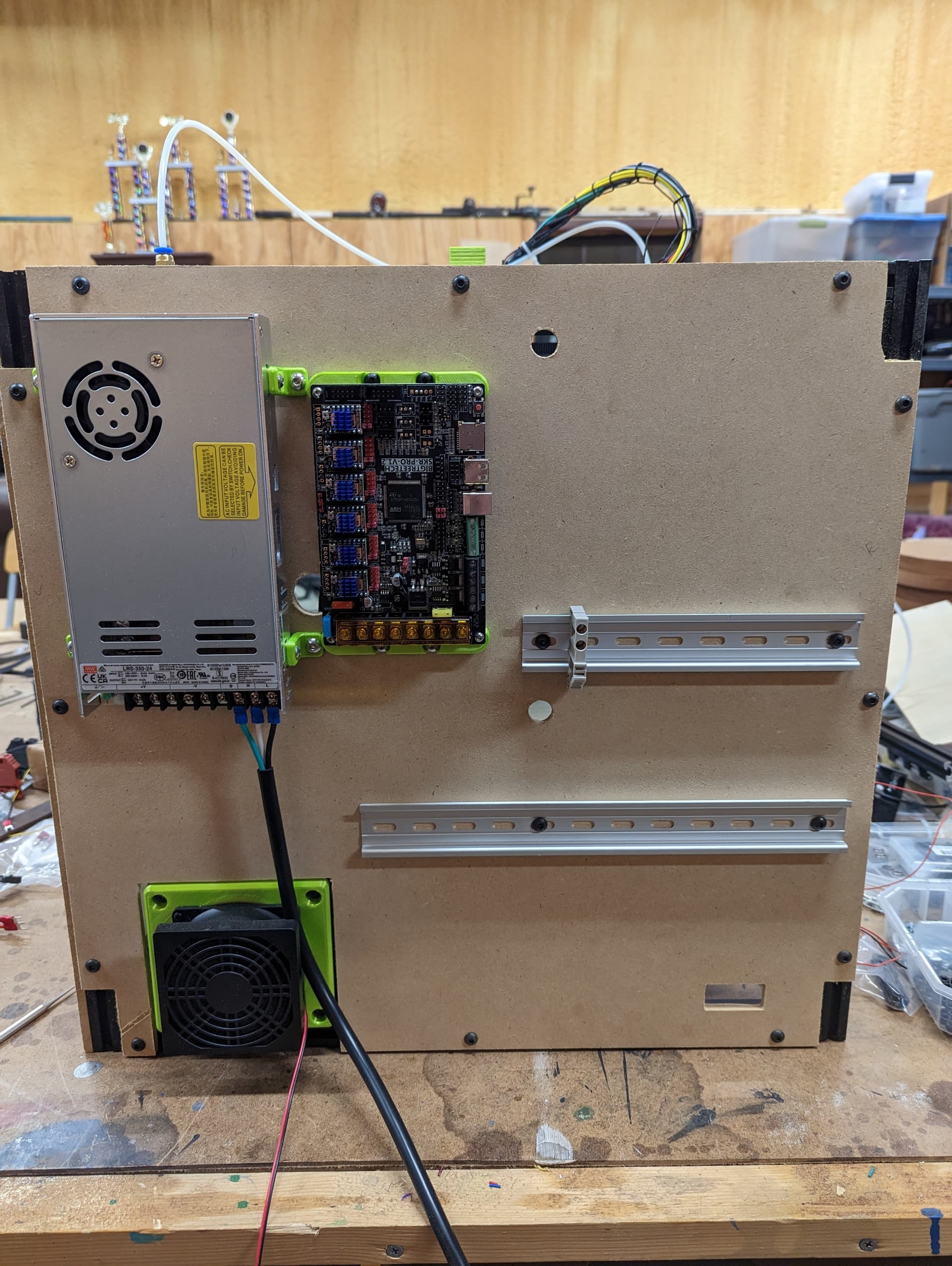
No shuffling, but I did just realize I forgot to put a hole for the heater in the board.
2 Likes
Minimal progress tonight. I have to recut the side panel for the electronics box.
The panel wasn’t square to the machine, so nothing lined up right. The vent is also too high up and doesn’t clear the corner braces.
The next panel I’m going to over cut and let the cnc cut the sides too.
3 Likes
Hey @niget2002, able to share link to the spool holder you’re currently using?
Am trying to fit spool inside on right side of the bed support plate. Need to mount to the panels, or add support/stand within the double wall polycarbonate panels am using (1/16" interior, 1/8" exterior).
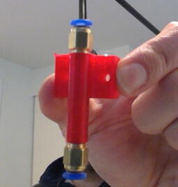
Thanks again for sharing your PTFE tube holder at Unofficial MP3DPv4 Bowden Holder by niget2002 - Thingiverse, am adding (and sharing) references to your parts in my build notes. Cheers!
Sure thing.
I’m using this one: Parametric universal spool holder by rowokii - Thingiverse
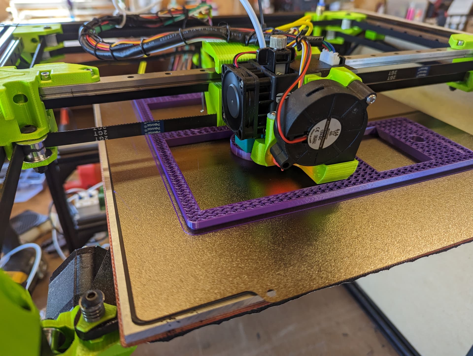
I also spent some time out with the machine during my lunch break today. I’ve been trying to figure out what to do with the umbilical going to the extruder. I had it attached at both the extruder end and at the back of the machine. This was causing it to bunch up when printing at the back of the build plate and was twisting the nozzle into the build plate.
What I decided to do is just remove the attachment point at the back of the machine. I cut a slot in the top of the electronics box. Playing around with the machine, I think the umbilical ‘should’ slide in and out of the electronics box as the gantry moves forwards and backwards. I think I’m going to 3d print some type of smooth guide to go in the back of the lid and the top of the control box It should help keep the umbilical from rubbing on anything sharp as it moves back and forth.
I’ll give myself bonus points if I can come up with a design that will keep the enclosure ‘enclosed’. Realizing that there will be an opening between the enclosure and the electronics box. Not really any way around that. When I start heating the enclosure for printing higher temp plastics, some heat will be spilled over into the electronics enclosure. The 120mm fan inside the enclosure box should still be able to keep things cool enough.
I might be able to figure out some way of attaching the umbilical inside the enclosure box that’s still contained to reduce that, but we’ll see if that’s even needed.
I’ve dealt with enough scope creep at this point, and really just want to get the initial build completed. I have more extrusion on it’s way so I can finish the lid.
I also got everything wired back up and was able to move the gantry around at lunch. I have a LOT of wires to shorten. When I first built it, I left everything way long because I wasn’t sure where everything was going. The placement is pretty much finalized at this point, so it’s time to shorten everything.
1 Like
Cheers for all the info and links David!
Do you have an idea of how much space you need above the top X/Y extrusions for the lid to fit the umbilical and PTFE tube? Am hoping to fabricate a lid later today, but don’t have everything fully wired up, and am having to guess space to allow, thinking 120mm?
Don’t have an umbilical wired up yet, was planning to sneak up the back somehow, maybe a printed part to force wiring horizontal and take strain off the print head. Am trying out EBB36 CAN bus, so not too many wires to wrangle. Am going to look at some examples, many CoreXY’s had to solve this already.
The SCAD based parametric spool holder looks nice.
1 Like