Not another MP3DP V4

Yeah. This design is using 6mm and 3mm aluminum barstock. I’ll tap the ends for 3mm bolts to hold everything together. I wouldn’t dream of making these parts on a normal drill press. Trying to get a 3mm thread in a 6mm edge is hard enough even with the mill.

I also realized while comparing my mock up to your core that the top belts sit proud of the bearing block a little. So I think I need to adjust the horizontal plate to make clearance for the two top belts.

And the two ‘big’ bolts being used to clamp the belts needs to be spun around. Once the extruder is mounted, I won’t have access to the front of the part for the bolts. But I should be able to access two lock nuts between the clamp and the middle block.

I really like the design portion of this. This morning I designed a 3d printed piece for wires to be zip tied to.

1 Like

Quick design question…

I’m trying to decide if threads in Aluminum would be strong enough to provide a clamping force on the belts. If I can thread the inner clamp bracket instead of fitting a nut, it’d be easier. I wonder how much clamping force is really needed to keep the belts from moving.

1 Like

One of my printers used an M3 screw into aluminum bar to clamp the belts.

It never casued an issue, but I re-did that with a 3D printed “comb” to grip the belt teeth. If I were to do it now, I would probably use a 20° V bit to carve the grips in the aluminum bar itself.

Even a shallow knurl would probably greatly increase the grip strength against the flat side of the belt.

2 Likes

I could definitely carve grooves into the plates to help bite into the belts.

I wonder if those same printed parts would work to rebuild a box style printer into a repeat. I have the carcass of a solidoodle workbench and a Colido X3045 that would be candidates.

Is the aluminum you’re thinking of using thick enough to get a helicoil into it?

Aluminum GT2 belt clamps are a common thing:
image

5 Likes

Yeah. I should be able to cut something like that into my clamps.

Here’s where I’m at with my design. Any thoughts are welcome before I start cutting metal.

Two big edits I did…

  1. I notched the underside of the horizontal piece so that those belts can be moved up a bit. Comparing my test assembly to the stock core, it looked like the belts needed to go higher.

  2. made the belt clamps taller so the bottom belts could be moved down some. Same reason as above. The stock core looks like the belts were lower. I also then notched the clamps on the bottom for wire clearance from the hotend.

Well… I guess there’s a few more edits. I flipped the clamp bolts around and made them M4. The original design had M5. I’ll thread the back clamp and use that to pull the clamps tight.

Thinking about putting the assembly together in my head, I think I can now get to all of the bolts as needed.

  • bolt clamp base to horizontal
  • attach horizontal to bearing block
  • loosely bolt clamps to clamp base
  • attach front to horizontal
  • bolt extruder to front
  • slide in belts and lock down clamps
  • attach plastic wire management and zip tie wires

I do think I want to try to mimic Ryan’s zip tie slots onto this. Right now I just have holes in the top for threading zip ties.

I’m printing copies of all the parts now to test fit again.
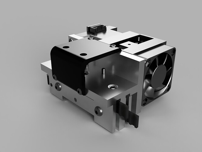
1 Like

I am doing everything in my power not to redesign the whole XY axis…

Test print looks good.

I want to redo the cable brace completely. I don’t like the way this one looks.

1 Like

So, what would that look like? :grinning:

I’m thinking it’ll require a metal sintering machine. 3d printed brass?

People are putting plasma cutters on Lowriders. Subtractive manufacturing
Why not put a stick welder on a repeat? Additive manufacturing.
Edit: Better make it clear: :slight_smile:

1 Like

You think you’re being sneaky huh…trust me my brain thinks about it a lot. I have 6 of them running, so I am always considering options.

Really at this point it would all center around a belt termination we all liked…but no complaints about the Z terminations? Very similar.

I can speak well of the aluminum clamp blocks. The ones I did myself were a favourite, because they only required one screw as hardware, but the commercially available ones (which also need a nut) are also very strong.

I really like the looping back style from the LR3 X Adjustment end, similar to the one used on the ZenXYv2.

The Z locks seemed to present fewer problems, probably because the belts could be installed without the blocks attached to anything. (At least that’s the way I did it.) Small parts could be adjusted and reprinted very quickly, if your printer wanted to make the belt loops undersized or oversized, it took little time and material to adjust so it was easier… I guess?

My v4 core, the belts were a pain to install, but after installation and tensioning, I haven’t touched them, so I am not feeling a lot of need for improvement there.

2 Likes

The Z axis belts don’t have NEARLY the dynamic load on them that the core does.

All that constant movement causes more strain on the belts that the Z’s see.

Plus. I think we’ve really decided that my real issue was the heat trying to print ASA causing my PLA printed core to melt :slight_smile:

This too… Much easier to install the Z belts than trying to pull the XY belts to the core and get that little belt piece to slide sideways into a groove. The Z belts just had the extra belt piece pulled inward into the part. Maybe if the core was designed so the belts went all the way to the other side, had the locking belt put on, then pulled back through the core to lock in place it would be easier.

1 Like

Playing with my 3d printed part today while sitting in a meeting…

I don’t like how all the joints are single-point stresses with 3 bolts holding them together. I’m going to add a cross piece across the bottom to lock the belt brace and the front piece together with another few bolts. It should help keep the weight of the extruder from flexing forward on the top any.

It might not have been an actual issue on the metal version, but it puts my mind at ease.

Further thinking… the 3d printed part on top for the cable should help with that issue some. I may be over-building/designing/thinking things.

2 Likes

One of the joys of being able to trigger print jobs on the printer in the shop from inside the house is not always seeing how much filament is on the roll…

I really need to invest in a filament sensor that works with Octoprint…

1 Like

Or add a second webcam focused on the roll.

Am already appreciating the Smart Filament Sensor on my mp3dp v4 running Klipper. The sensor has already helped detect filament clogs and auto paused the print job for me to fix cause (filament broke and jambed in biqu gears. Suspect filament end was too curly when being inserted and ended up going where it shouldn’t when being loaded).

1 Like