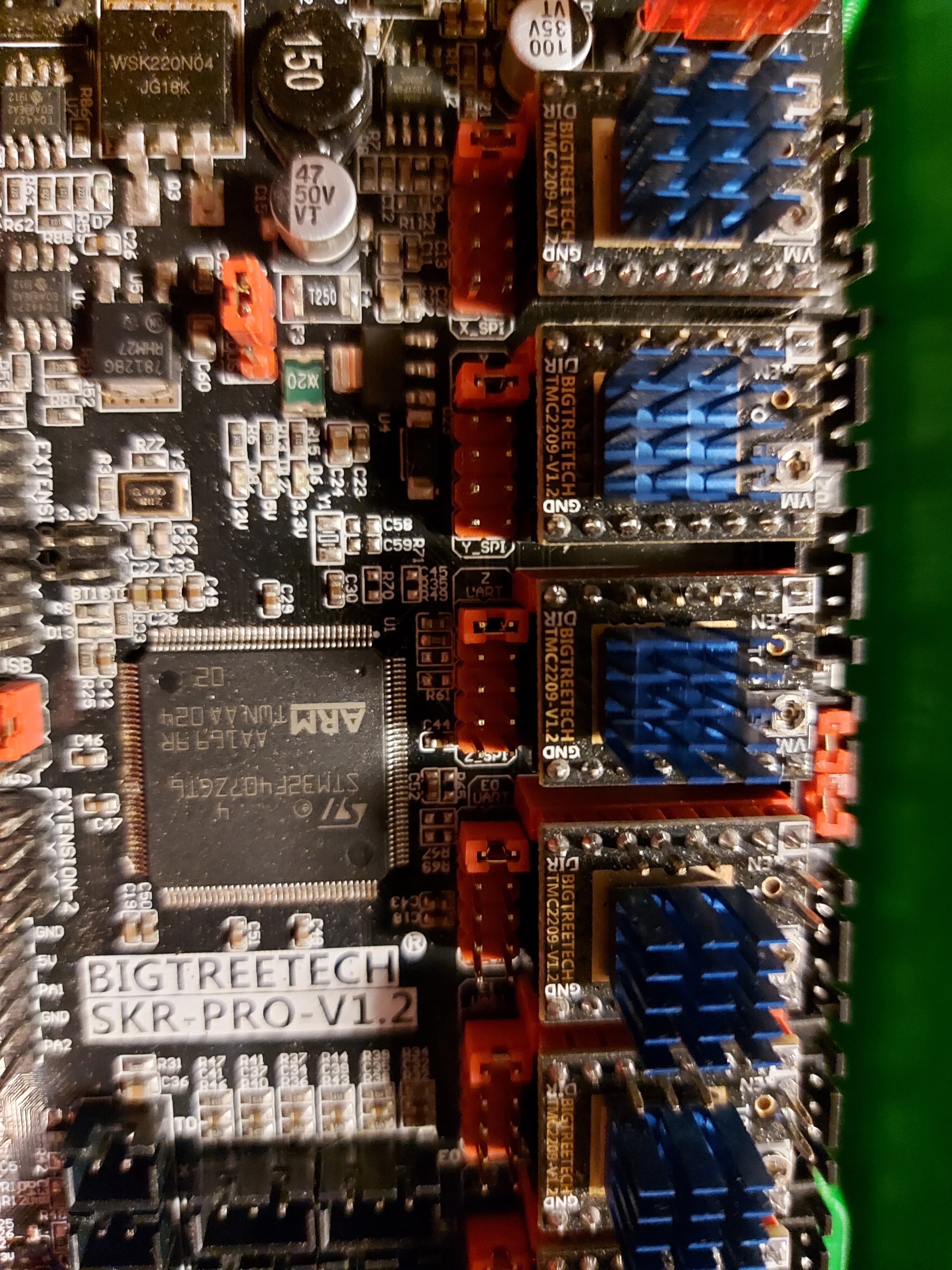
So i have my motors moving for a new build using a SKR 1.2 pro. However, i was never able to home and couldn’t determine why (it would just ram into the endstop and keep trying to move). I’m using the firmware in the ‘V1CNC_SkrPro_Dual_2209-2.0.9.2.zip’ file.
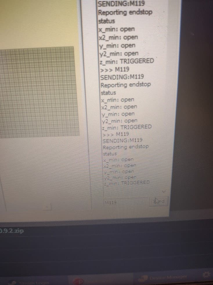
So i brought a computer down to it and hooked it up with pronterface. Nothing. The end stops don’t respond at all when triggered using M119. I rigged up a dummy switch (yellow and green wires into X1 in above screenshot) and still no triggered response.
The switches need to be wired as “normally closed”, NC pole and COM. That way if you had a broken wire in the endstop circuit it would fail immediately. The endstops should all read “closed” unless they are triggered. Try that with your dummy switch and see what it says.
I don’t think you have a Z_Min endstop installed, but you can see it as triggered, I.E. open.(no connection).
Marlin will report the endstops as either Open or Triggered.
With the default V1 firmware, this is counterintuitive, because “Triggered” means no continuity between signal and ground, and “Open” means that the circuit from signal.to ground is connected.
M119 should report all stops as triggered with nothing connected to the board end stop pins at all. It should report Open if you put a jumper from signal to ground. Z min is opposite though since it is configured for the touch plate. (It will cause problems if you jumper +5V to ground so be careful not to.)
The end stop connectors are +5V, Ground, Signal. We typically only use the Ground and Signal pins.
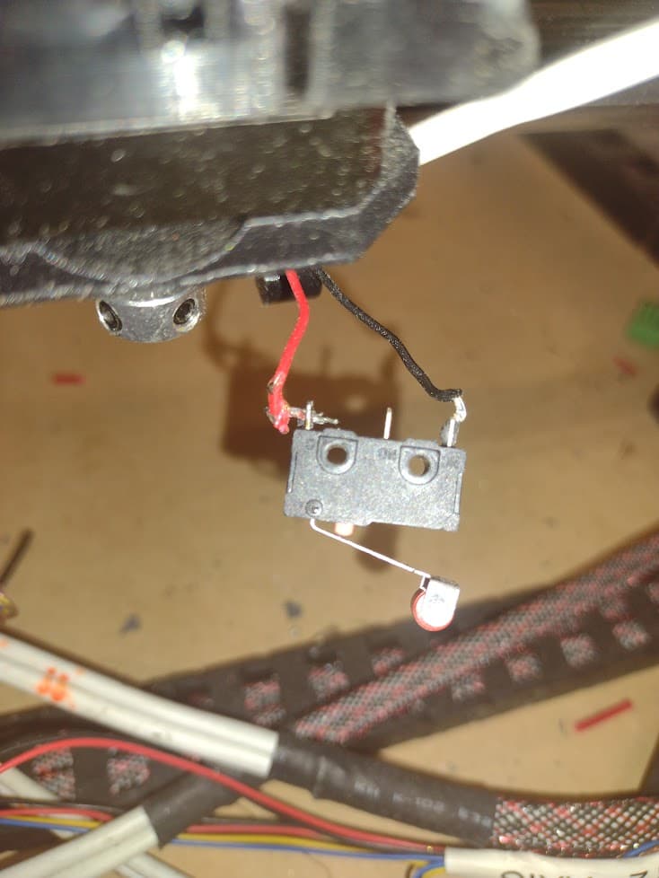
Like Mike said, we want to use the C and NC poles on the switch, and leave the NO unused. Those need to go to S and Gnd on the end stop side. If you go to the +5V and S pins on the board, it will do nothing. If you use the NC and NO pins on the switch it will do nothing.
That switch appears to be corectly wired, and looking like that should report “Open” if you press the switch it should change to “Triggered” unless it is on Z Min, in which case it would be the opposite.
Pressing the switch and re-running M119 reports no change. My pronterface log was me pressing, releasing, pressing. Each time it comes up with the same results.
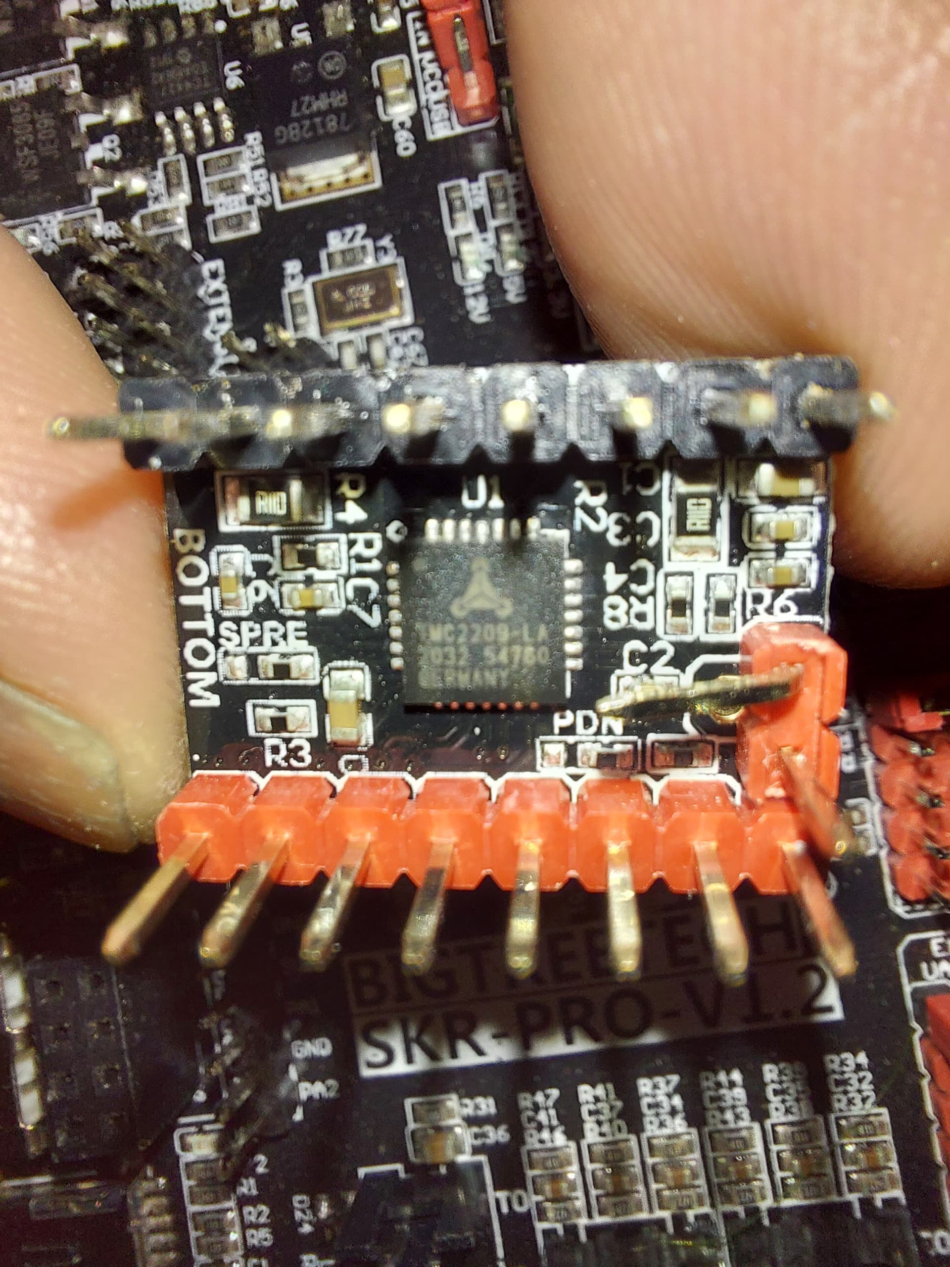
It looks right, but to be sure, it needs to be connected to the 2 pins furthest from the stepper drivers. I figure it must be, because the 2 cliser ones will short 3V3 to ground… but to be sure
I find it odd that Z Min is reporting Triggered. That should need something connected. I might try to reflash the V1 firmware, because something ain’t right there.
Yeah, i read the wire up description on the website and watched a few videos. Its connected to the bottom two pins of the 3 pin set (relative to the picture orientation)
I tried reflashing the firmware 3 times now. Every time it changes the firmware file extension on the sd card. This is a new board and i’ve never been able to get it functioning.
That one pin needs to be either bent out of the way like that or else clipped. If it is connected, the board ignores the limit switches. That would be consistent with what you are seeing. Also the jumpers should be set like so…
My guess would be the diag pin needs to be removed. If you remove your dummy endstop, no matter which way it is wired (and it looks right to me), it should say “triggered”.
I do have a few switches where the labeled pins are in another order. Rather than just connecting the two outer pins, look at the labels and connect to the C and NC.
If you zoom in on the picture, one shows the “C” and “NC” labels. – the one near thr truck. I believe that they are wired correctly.
But not Z Min, which is the only one showing “triggered” in his log. Z Min is set up in V1 firmware for the touch plate, which works as normally open switch, or at least that’s how it was when I had the SKR Pro connected to my LR2. I never tried the TMC drivers with the diag pin unbent, but it makes sense to me that a PCB error that does that would bring the stop input to logic low (Open for all stops, except Triggered for Z Min)
I should try it with my SKR Pro. It still has the Dual LR firmware installed on it. I think the pins will survive unbending and re-bending to prove my hypothesis.
Okay, I just tried it on the X and Z drivers, and I get the exact same results. It reads X as “Open” and Z Probe as “Triggered” (IE: Logic Low) regardless of whether I have anything connecting the signal and ground pins or no. I am 99.999% sure that this is the problem, with the other .001% being that somehow the OP managed to toast at least 5 of his input pins without toasting the whole MCU.
Bingo. I hadn’t bent the pin because i was unsure of what the ‘sensorless homing’ feature was and i didn’t want to damage the controller before i understood what features i needed and didn’t. After bending the pins, i was able to home my X and Y axis. Thanks for your help guys.