This results in a larger than necessary build size, with that slight de-optimisation. Probably not a deal breaker, but there it is.
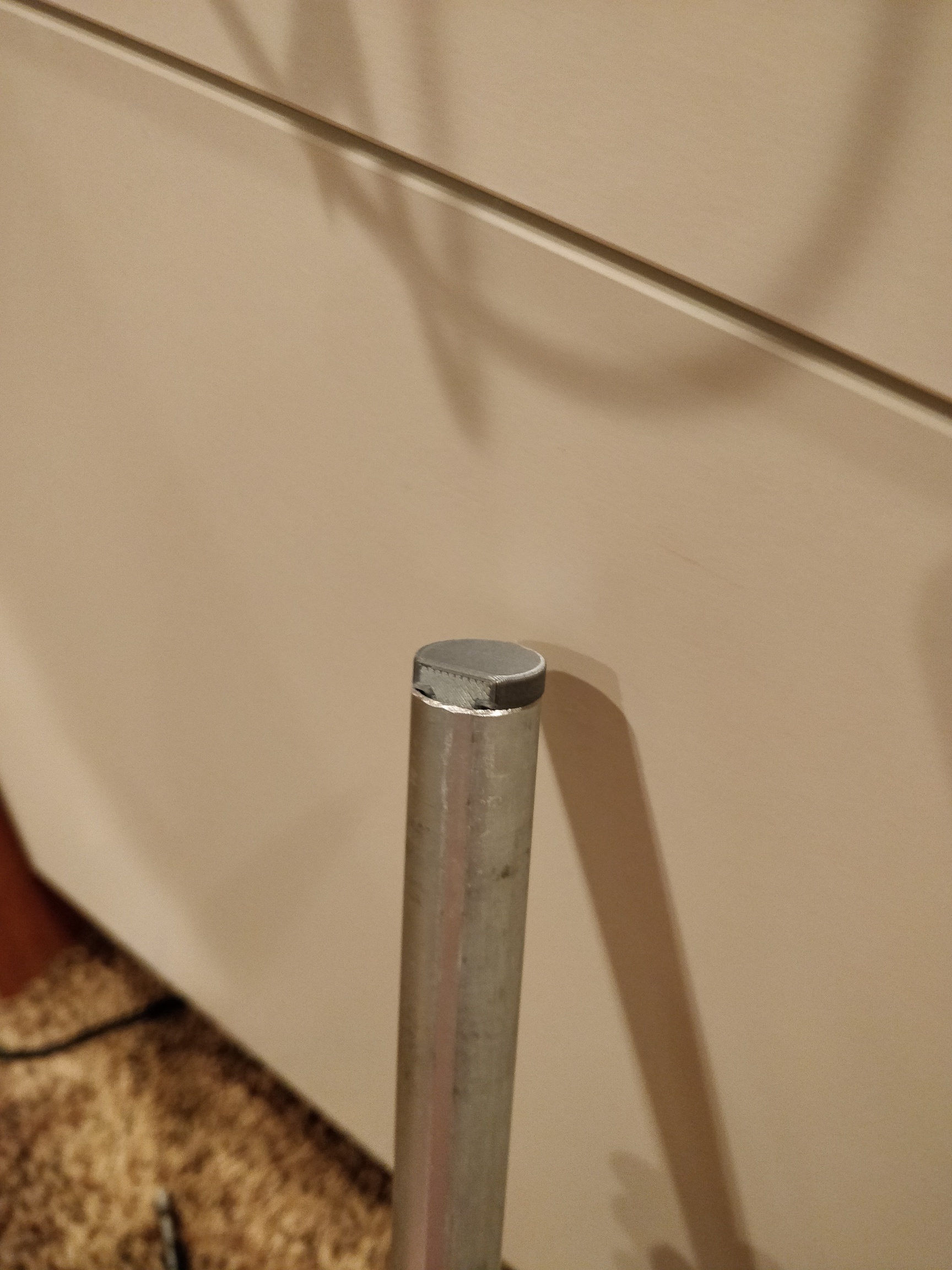
This results in some problems with the homing cycle. This is what I did before. Magnet strength is square law losses, so even a couple mm extra distance between the magnet and the ball increases the chances of “losing the ball” geometrically. If you get a build-up of sand at the home edge of the sandbox, it becomes very likely that this will happen. Maybe not every time, but it will almost certainly happen. For reference, my table bottom is 1/16" material, and the magnet surface is maybe the thickness of a business card from it. (Just checked, a business card has friction when I try to slip it between the table and the magnet.) So that makes it less than 2mm distant from magnet surface to marble surface. If you double that distnce, you get 1/4 the holding power of the magnet. That’s 2mm outside of the table area. The switches have a mechanical travel of about 5.5mm from rest position until trigger, so at 2mm outside of the area, you will still get contact with the switch arm. (No loud click, but contact nonetheless.)
I bought 6 optical stops on Amazon for $10 CAD. This would make the “each” price $1.67 CAD. Guessing from V1’s regular pricing on items, this probably means that it’s maybe $1 more than the mechanical switches PER PAIR. And if it’s overall better, why not?
This still does not resolve the core problem with the X switch, which is this: If X is already at zero when you home (Homing twice in a row, or you ended a pattern with the marble at X=0) then the switch gets contacted 90° away from it’s normal mode of operation. This can cause problems with the switch operation. My original ZenXY table kept breaking the snap lever off of the limit switch. I am planning to build one of these and give it to a person who is not at all mechanically inclined. She would be able to use it until the switch lever broke, then I would have to come fix it. When I was using it, that snap lever would break out in 5 days, tops. Sometimes I could re-fit the lever, if I could find it, and if it didn’t break the plastic switch casing, neither of which was certain. There is a way that this can be mitigated, but it would require re-working the CAD anyway, so why not just engineer it to be all around better?
There are plenty of solutions, and the problems are far from insurmountable. None of the issues that either Ryan or I have identified with the beta will stop you from being able to build a perfectly usable sand garden table. The improvements over the version 1 table are plentifold, and obvious. I would entirely consider it worthwhile to build the beta version as an improvement. I will not likely change my beta version once the CAD work is complete, I’ll more likely just build another one.
But is it enough? I don’t know how many hours Ryan has put into the design of this, but to leave something wanting would be a shame.
My 2cts, I believe optical end stops would be perfect, it’s one weak point less in the build, and the benefits that’ it’s soundless is a great bonus.
One other way would be be to use stall guard features from the tmc2209 with my cheetah board.
I’m waiting for this build to be released to test with clicking endstop, then try to use the stall guard, my marlin firmware mods are ready, just waiting for the design now.
The downside of sensorless here is we are typically, 50/50, already at a home. When there it does not trigger well, or at least it seemed to be hard to tune for me. I would like to try again as it was designed for it.
I can’t tell you what else you may have missed… I’d actually call that a half twist in the tubes, changing from tooth side in to flat side in.
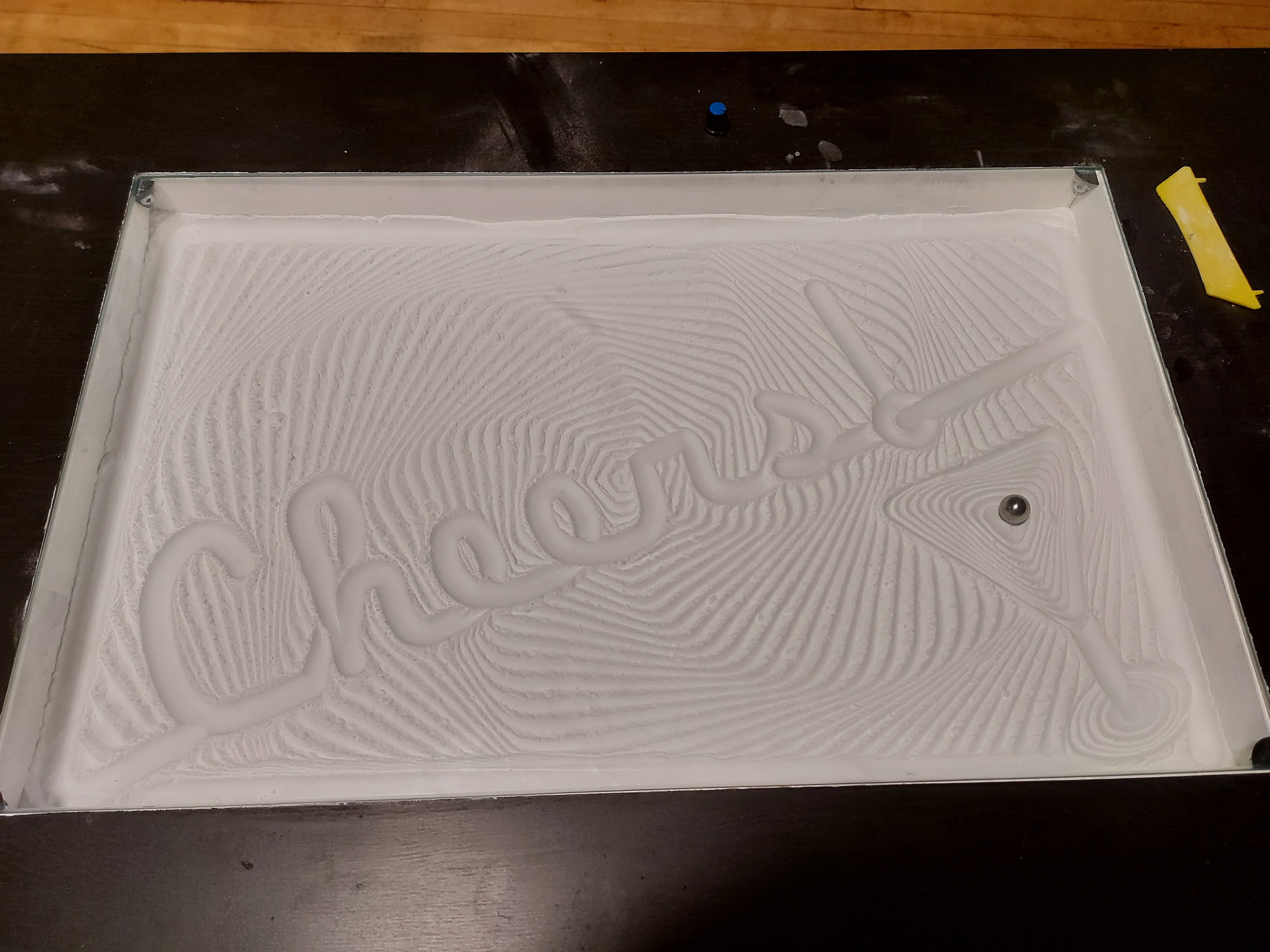
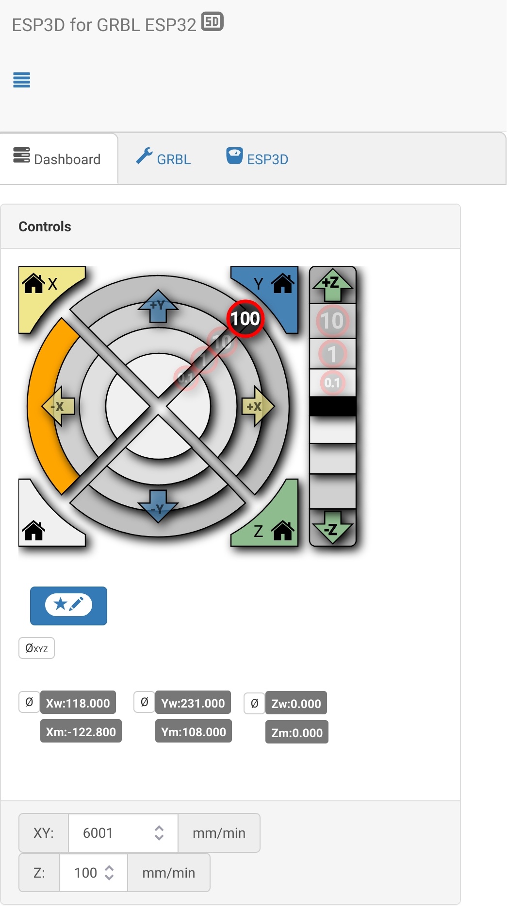
I’m running mine now, at 6000mm/min, doing a table wiper. I have a very small misalignment with my homing switches, and the ball clacks against the end of the table at Y=MAX a little. I could fix it by redefining the table to be 1mm shorter in sandify, but I’ll probably fix the home switches.
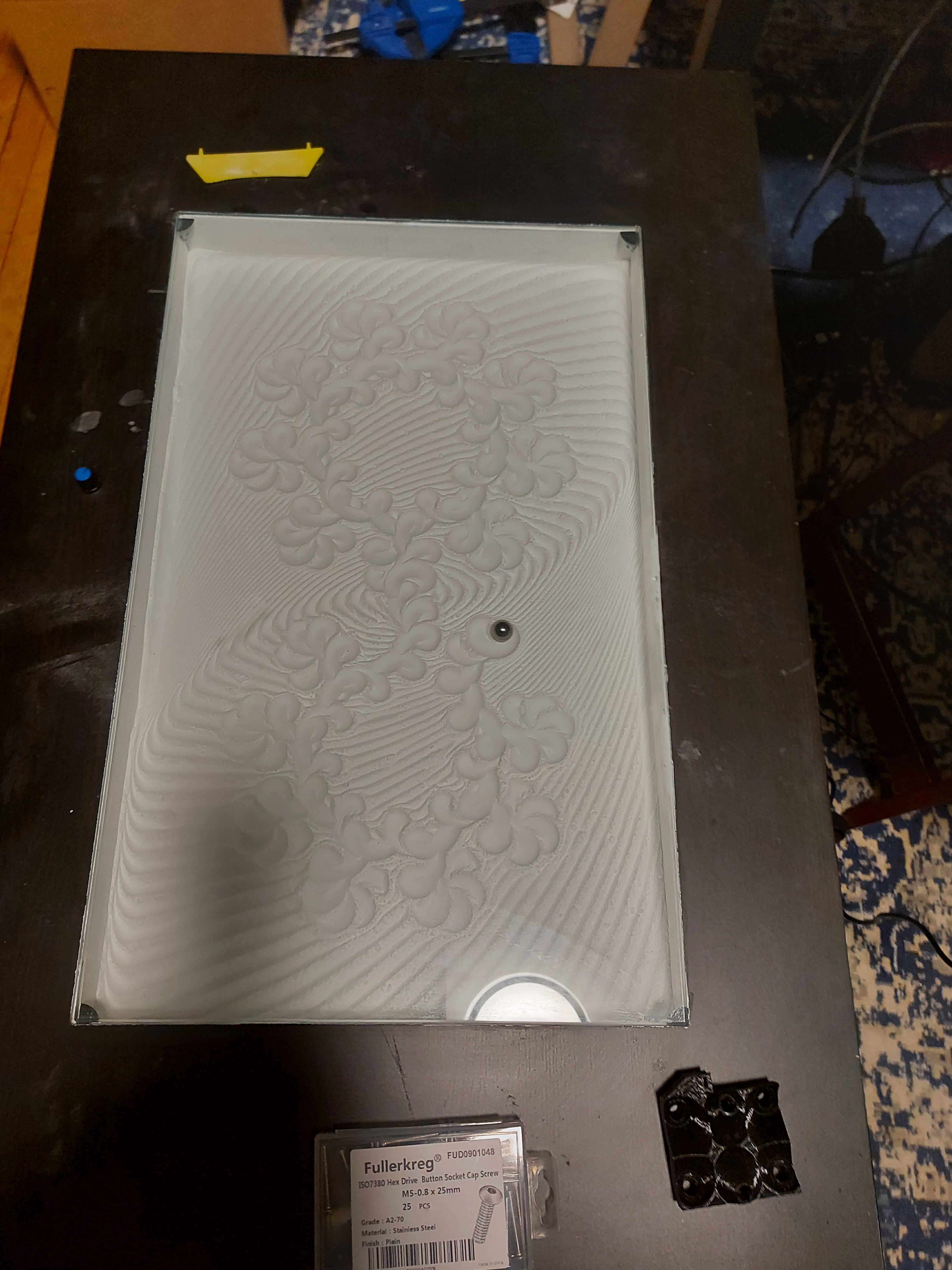
It’s running great otherwise. A fresh box of baking soda, so there are a few small clumps, but it’s running at at least half again as fast as I ever got it to work with the first build. (Wiper finished, so now I’m running some of the same files that I used to, just… faster.
6000 mm/min, yeah 6m/s would be pretty extreme, lol. 100mm/s is trucking right along. Most sandify stuff can’t go that fast through the 8 bit arduino. Dunno if its the SD card rate reading the instructions, or just recalculating the movement, but it gets a bit jerky in the text, and at the small points of some shapes.
I actually don’t plan to run it that fast, the speed it was before is good.
I’m guessing it is the command rate. I have to choose when to do high resolution and when to do more blocky, and I haven’t really optimized it. I just crank up the vertices. I should probably spend a few hours profiling and seeing where I can reduce the resolution without hurting anything. I am sure there is some low hanging fruit. I have wanted to try the “arc welder” plugin for octoprint to see how much of my stuff it would just turn into arcs. And then I think, maybe I should just do my own arcs, then I just park the idea.
I love to see the patterns. I just tightened the belt on mine. I am going to do a few moves, and then call it a night.
Wait, I think I might have thought of something. At least it took me a while to figure it out.
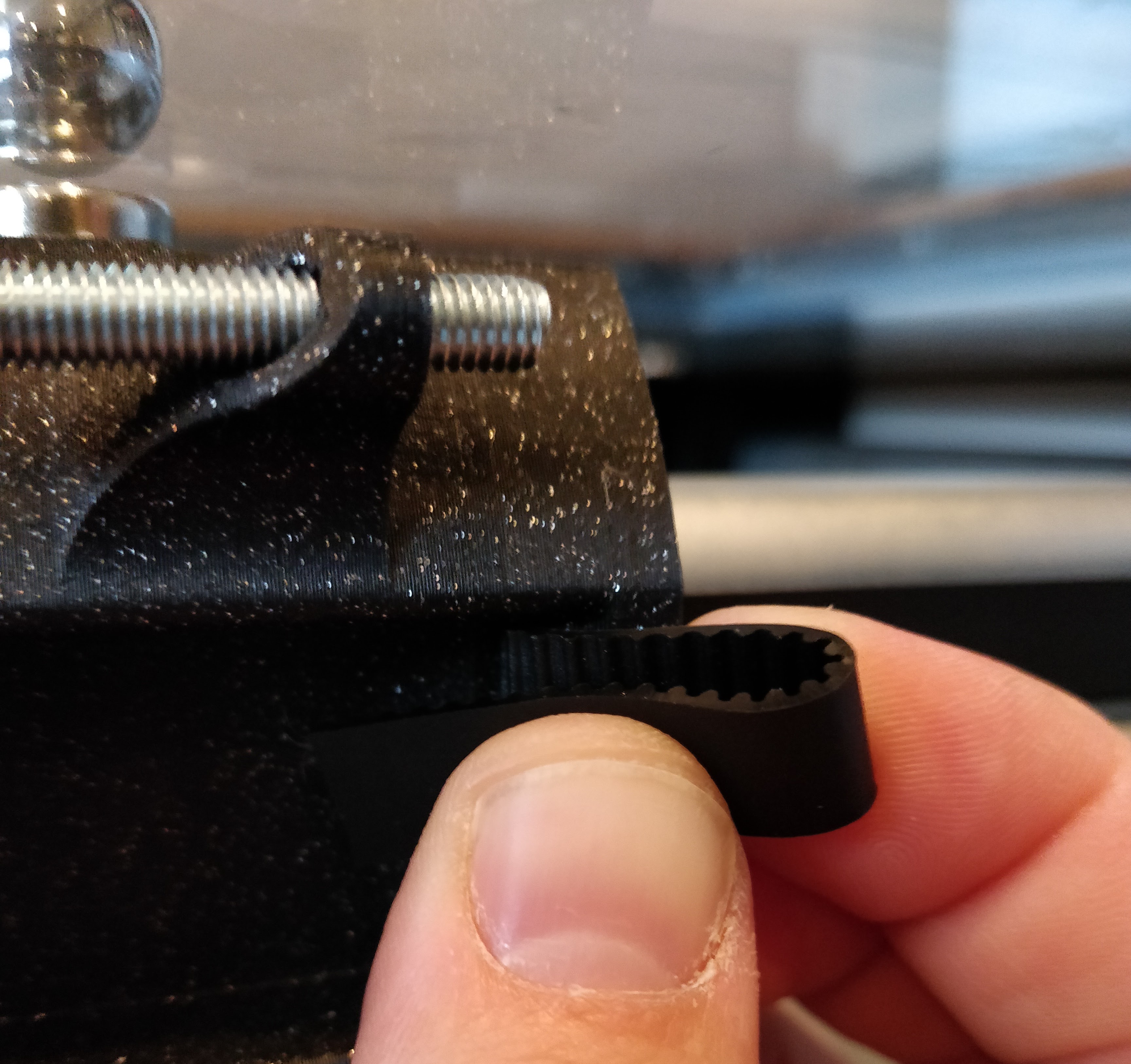
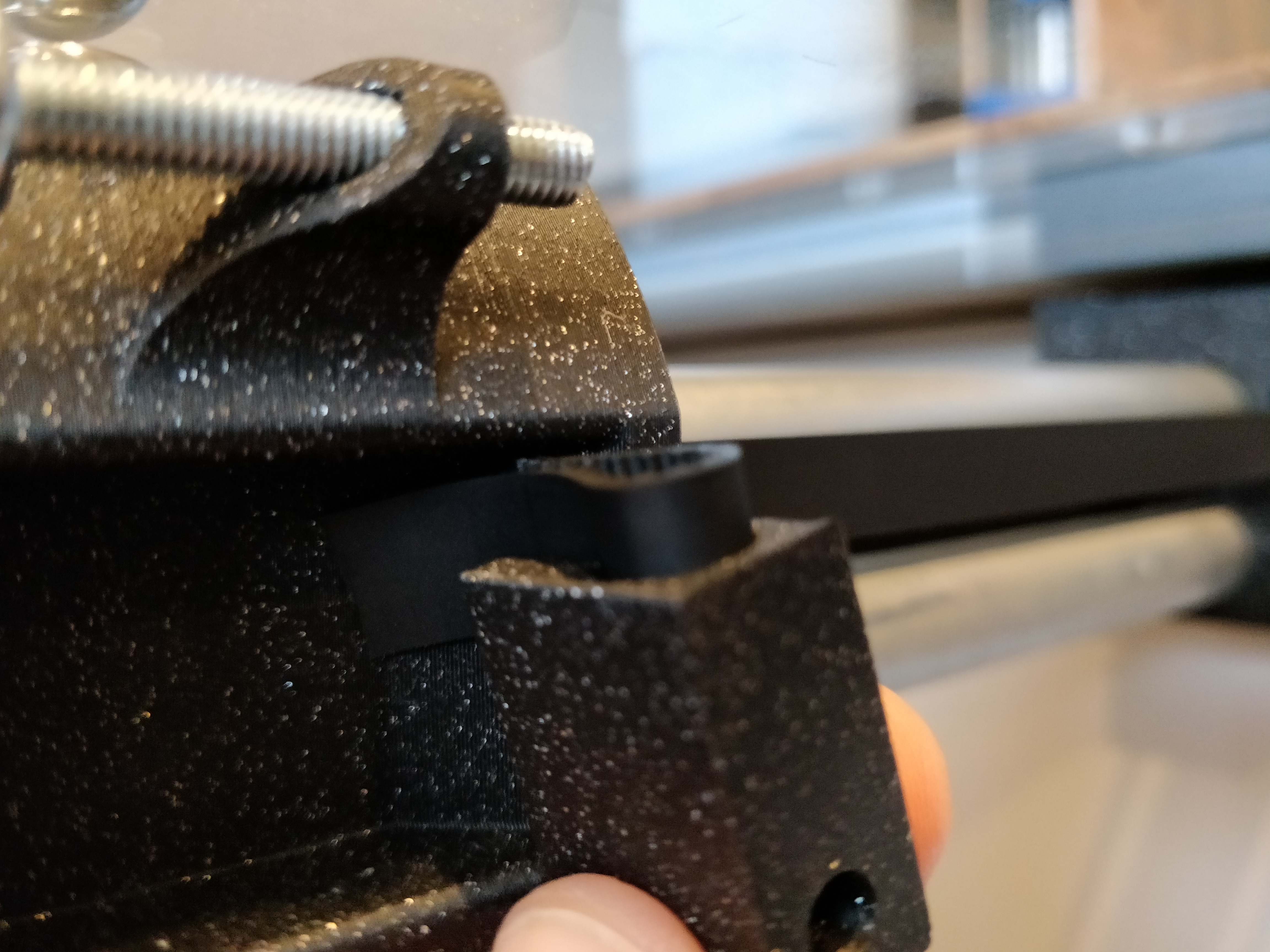
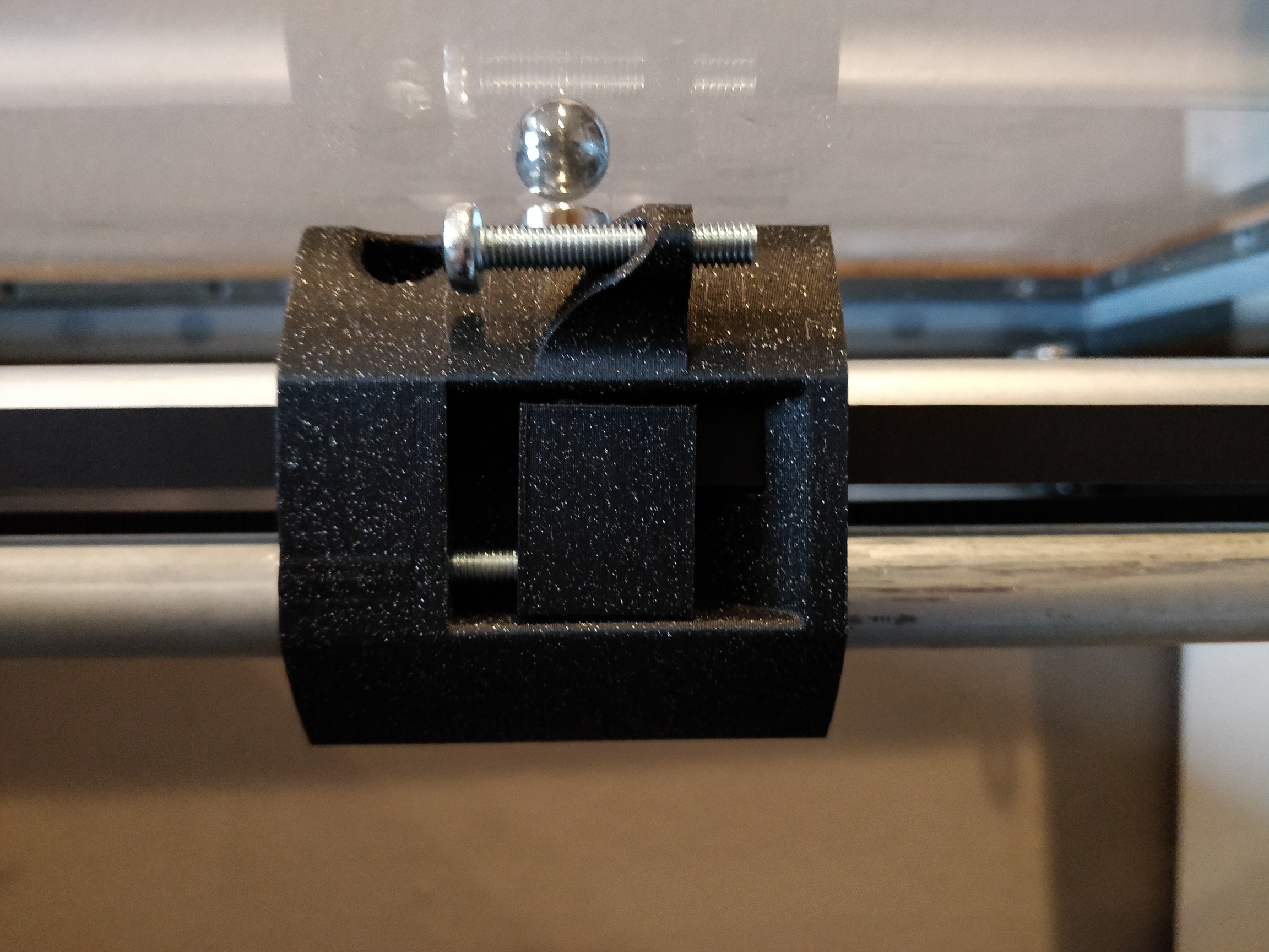
To get the belt into the tension block, there’s not much room. It has to come through that little slot, and then into the block with only a couple of mm to spare, and it comes in from right next to the table. I couldn’t see it and get my fingers in there at the same time.
Pull the belt tight, and square up the rails. Mark where it comes through the slot, so you can use that as a guide for where the tgension block will go. If you unbolt one of the pulley corners from the table, and pull the 1/2" conduit out of one of the trucks, you can then pull several inches extra slack through the slot so that you can more easily put the tension block on the belt. Then once the block is on the belt, pull the slack out, put the 1/2" conduit back in the truck, and bolt up the idler pulley corner. Shaved a lot of time off of my assembly, since I spent a good deal of it fiddling with that block. The worst was the time I got it back together, then there wasn’t enough movement in the bolt to properly tension the belt, so I had to pull it out and do it again.
It actually wasn’t that bad… but this way was still way easier, and repeatable.
I managed to get that part without taking anything off. I just pulled on it to make some tension, then I wrapped it on itself to make it stay and then I pushed it into the block. It was all a very good fit.
Everything about this build has been great. The only part that really stressed me out was/is bolting the corners down. It is hard to get them where I want (and the cabinets aren’t perfectly square, who installed these?!). Having to do all of that with everything already assembled is tough. It would be awesome if there was a way to clamp the tubes and stuff in place, and square while I was marking and adding the holes. It may also be that I am overly paranoid on perfection.
But honestly, this is a really fun and addictive project. I have 438 X and 421 Y and I have about the same amount of gap around the whole space (1 1/4"). This is really working well.
I was also a little extra paranoid about putting holes in the epoxy surface that I needed to be able to hold anything in there. I ended up snapping chalk lines for the hole locations, and pre-drilling.
I measured off of the .STL files (Not the most precise, but good enough for some #6 screws, I figured.)
I came up with the following for offsets from the outer edges (Which are 92.5mm away from the work area)
Y Offset, power corners: 50mm (49.95mm measured)
Y Offset, cross corners: 19.05mm (Which I figured was 3/4" so probably correct.)
X offsets, Power/Cross Corner 1: 10.5mm, 67.8mm
X offsets, Power/Cross Corner 2: 8.8mm, 66.2mm
Having pilot holes for the screws gave me a lot more confidence in mounting the pieces, but I still checked the diagonals for square before I bolted everything down. (For what it’s worth, the pilot holes were perfect off of those measurements. Less than 1mm difference in the diagonals, but that’s also based on the box that I made before to match the glass.
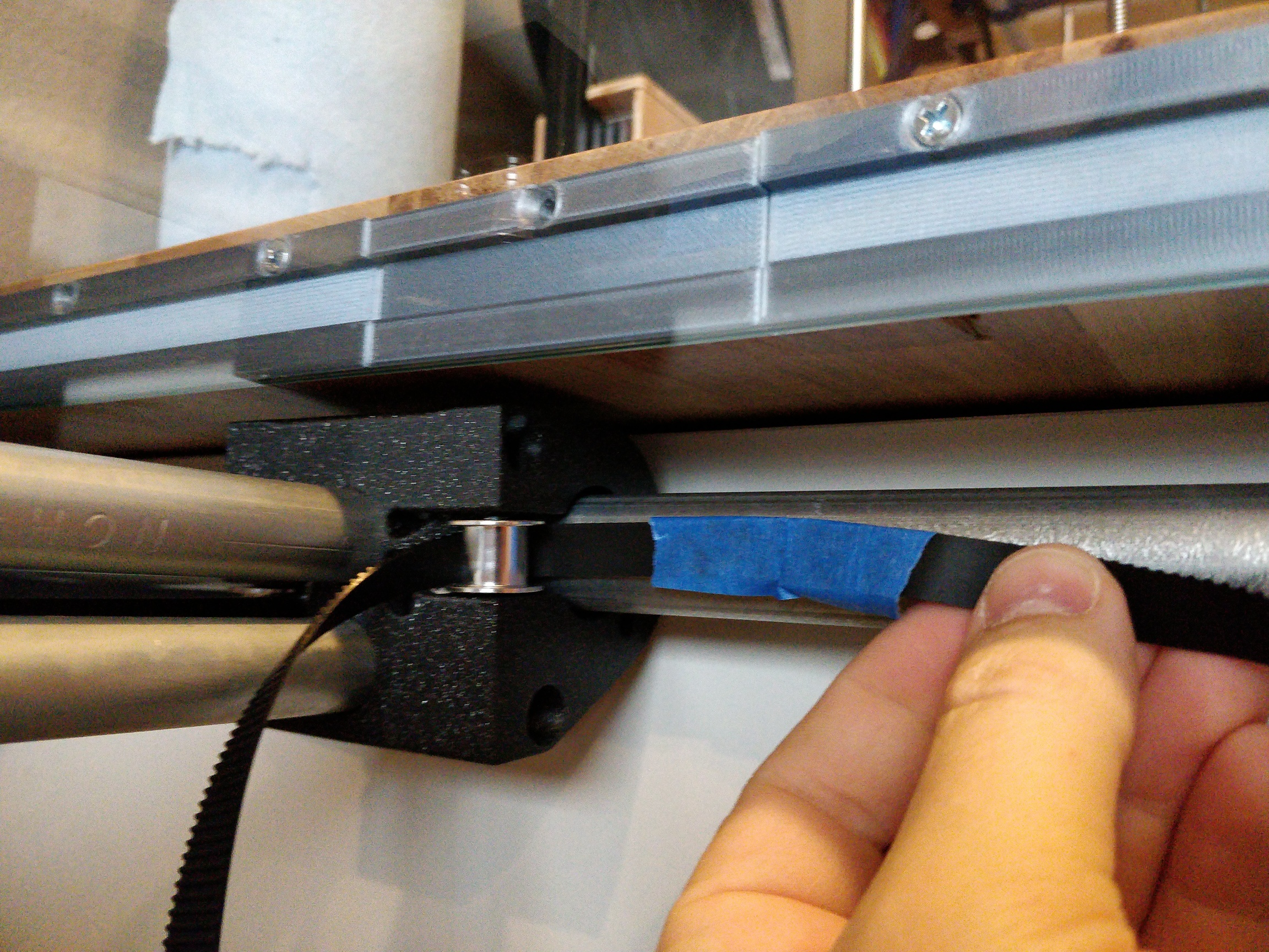
Here is a picture of how I got the belt through 2 tough spots. I just fed some scrap through the other way (from left to right in this picture) and taped the two ends together to snake it back through. It just needs to be strong enough to pull the end of the belt along the correct path.