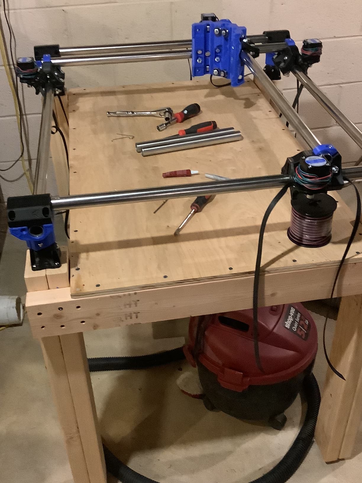
Lots of progress to report.
Physical build is complete and squared. It’s really important to square at each step, follow the instructions.
The Manta instructions PDF is pretty good, but not abundantly clear about the use of SD cards. You actually use a second SD card in the process.
Being a newbie, I used Neil’s files. But he has the 1.0 board and I have 1.1
If you use the Manta board and Klipper be careful about which version Manta board and the pinouts for motors. They are mostly the same but I wasted some time chasing down an error that turned out to be due to one pin assignment for the Z motor. Details are in my questions to Neil in his build log
I left the belt ends off until after I got the motors all running and in the right directions. The motors do need to be attached to test the end stops, because you can’t fake it and push end stops quickly enough.
Jump pins for 2209 drivers This is clear enough in the Manta PDF
Jump pin for 24 v motors I need to re-discover the link for this. There is a jumper needed so the board passes the same voltage to the stepper drivers. With this board it is possible to run even higher voltage steppers, but from what I read, 24V is enough. So I just have the whole board running on 24V.
Wiring routing
Most of the above was done by simply plugging the stepper motors to the board, with the 4pole Dupont connectors. My motors had 1meter of wire with a 4gang Dupont connector
I guess the above means that Dupont and Molex are slightly different. I obviously needed to extend the stepper motor wires. I bought a set of Dupont connectors and a crimper, but I couldn’t make a reliable connection. So I used the old “twist, solder, and heat shrink” method on the motor wires. All of these connections are hidden in the tubes, or in a position where they are not flexing.
In the box for the Manta board, I needed to put Dupont connectors on the wires. I conneccted them to pre-made Dupont jumper wires. I couldn’t find a nice terminal block for these fine wires. Rather than putting heat shrink on each wire, I printed an insulating terminal block to hold and isolate each wire joint. After “twist and solder” I “potted” each join into a cell with a 3D print pen.
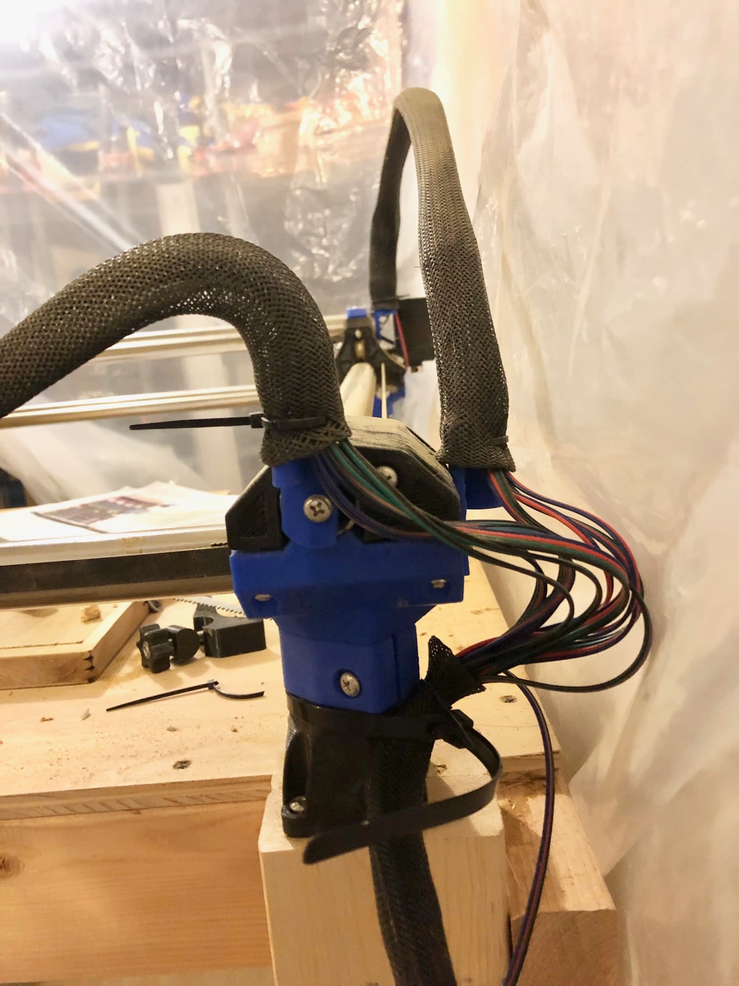
I looked for the simplest way to route and protect the permanent wiring, and came up with:
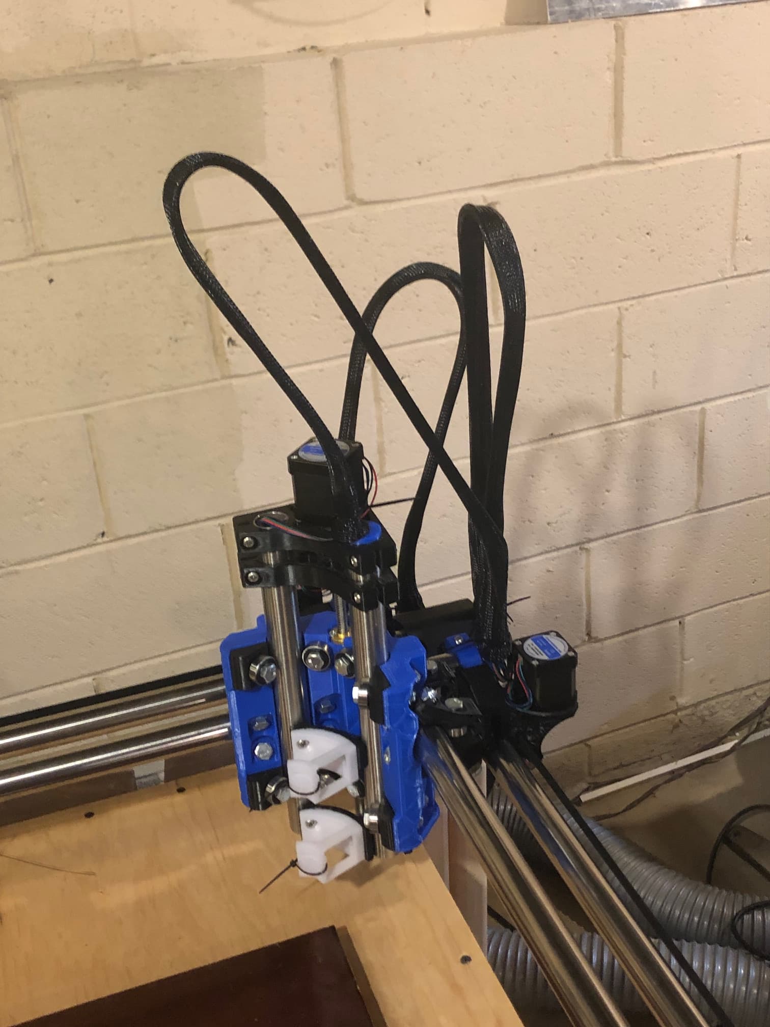
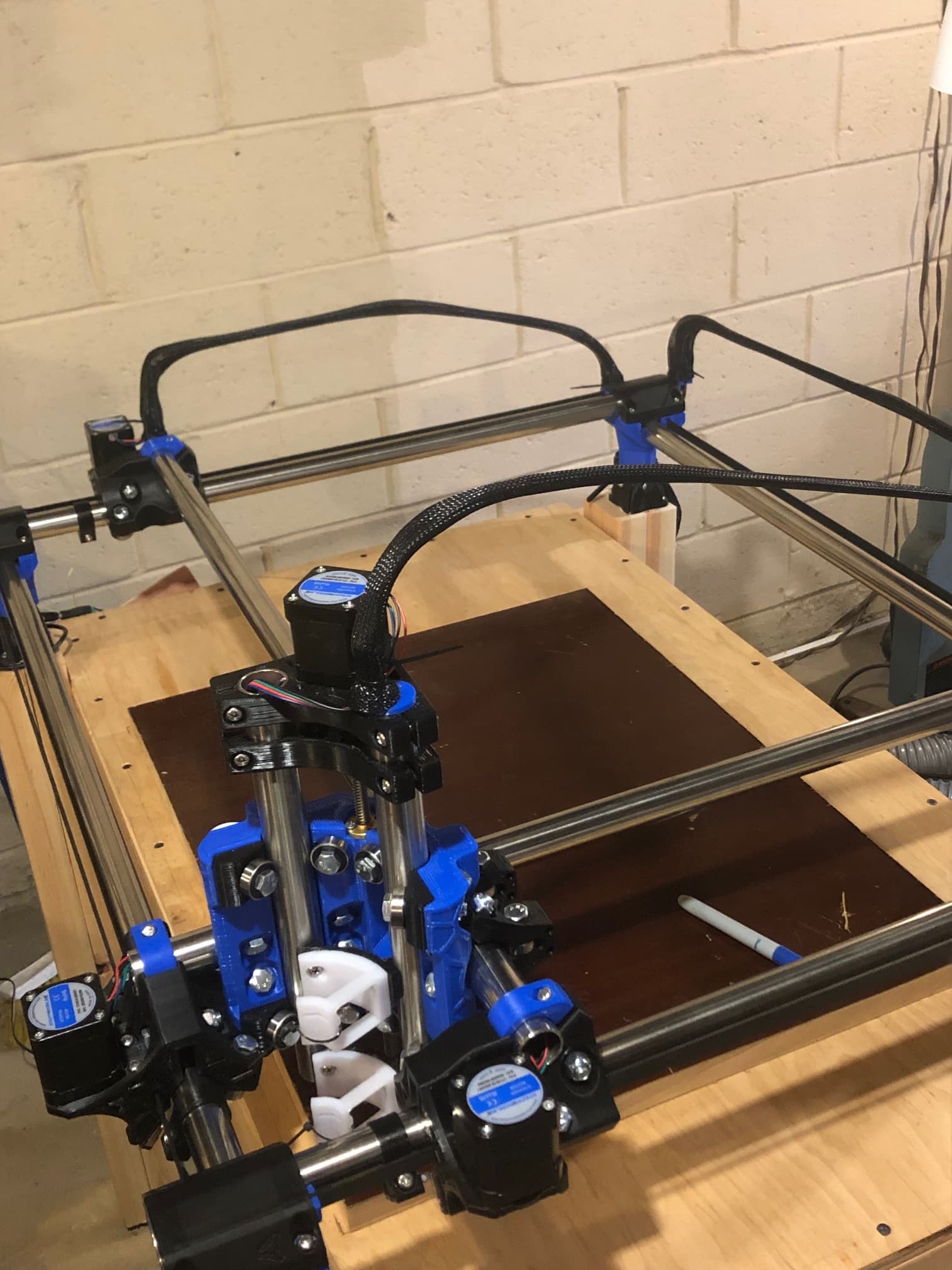
TMTVV “Tape Measure Trick Vertical Version”
One added beauty of the “tape measure trick” is that the tape can flex in 3D. So unlike the drag chains, I didn’t have to make mounts to keep the wires orthogonal to the frame.
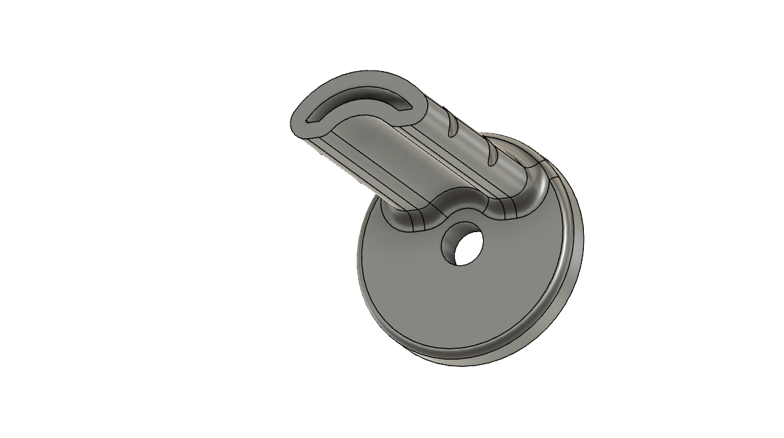
I made clamps to grip inside the tubes. These leave a space for wires to exit. They use the same M5 bolt and nut as the mpcnc assembly. They fit a cheap 1/2" wide tape measure.
I had to reprint the belt tensioners. This time I used a 0.4 nozzle. My belt is too fat and the tensioners were too big for their pockets. In Fusion, I had to simplify the mesh 25 fold twice to get a simple enough body where fusion did not crash. Then I could reduce the whole thing to 98 percent and redraw the slot and ellipses to make the belt fit.