This post is 2500 for me too. I bet some deleted
Edit: look at the url or permalinks, that shows your post is really 2522. None of this matters or relates to the Primo though
This post is 2500 for me too. I bet some deleted
Edit: look at the url or permalinks, that shows your post is really 2522. None of this matters or relates to the Primo though
Lol. It was late and didn’t want to miss it. 
That’s interesting, but now I’m slightly annoyed by that 
And I can’t think of a single post on this site that has stayed 100% on topic.
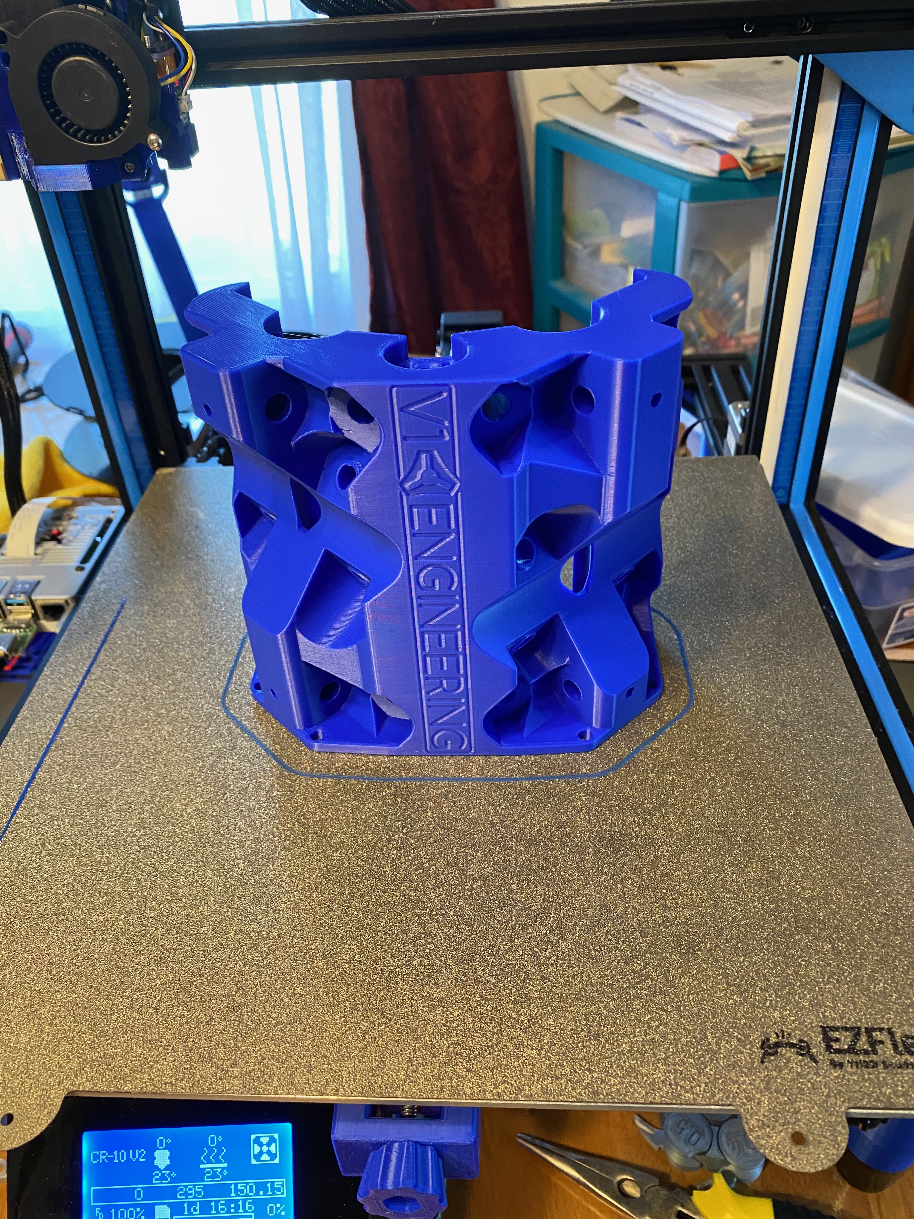
I finished the mechanical portion of my Primo build yesterday. It feels like a much more substantial machine, and I’m very happy. As I put it together, I had some thoughts about the build process and instructions.
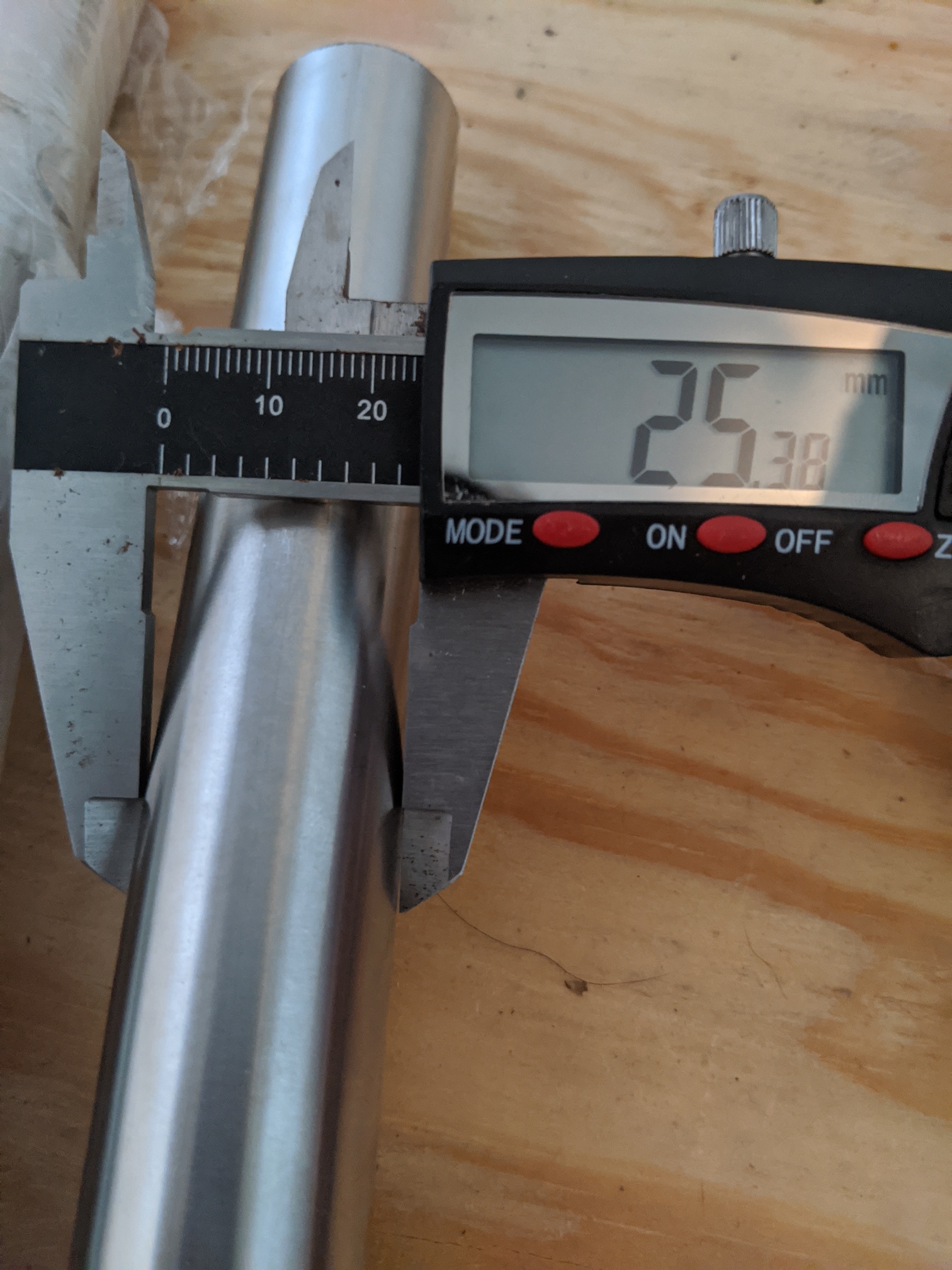
It is much easier to adjust the leg length before the legs are mounted on the board. Attach the feet so that they can still be turned on the pipe with some effort, attach the clamps until they just bite the pipe, and use either calipers or a fine rule along with some twisting and tapping to adjust all four legs to the same length.
Printing the first 6 to 8 layers of a foot creates a nice template for laying out the holes for mounting the feet. I was struggling to accurately mark the board for drilling using a completed foot.
There may be a reason for the order, but to me it appears that the clamp and the corner bottom could be put together before the clamp is slid onto the pipe. This would avoid the need for glue to hold the nut in place…a potential source of issues if any glue ends up on the threads.
It would be better if the before and after idlers picture was taken from a higher angle so that the part of the top of the idlers is visible. As is, the picture just shows two nuts appearing.
It would be nice if the picture with the assembled stepper on the truck showed the direction the wire comes off the stepper…or alternately it is mentioned in the instructions. That information is easily found in pictures elsewhere in the instructions, but a first time builder might not know to look for it, and it might be a pain to redo stepper mountings once the machine is assembled.
The holes for mounting the limit switches were a bit too big. When the screws were cranked down as far as they would go without stripping, I could move the limit switch if I applied a bit of force. While these switches don’t have much force applied to them in general use, my concern was if one of them got bumped, I’d have to redo the switch alignment. I coated the inside of each hole with some gel CA glue and let it sit overnight.
In squaring the trucks, it was hard to get an open-ended wrench on the nut closest to the stepper. I wonder if the “socket” this nut lives in could be cut back a bit.
In the core, I had difficulty pushing two of the four bearings into their slots. I used a clamp to press the bearing into place.
It is going to be a bit before I get to the wiring and electronics, but I’m excited about this upgrade.
Because it mounts on the angled surface and not the flat, during my testing putting them together actually clamps the lock enough to not allow a leg in. I think I have a blurb about this in the instructions. I also feel most prints will not need glue, mine did not, it is a drafted cut so if you seat them they should be pretty snug, this does vary with each printer though.
I do my best but I can not account for all printers and this is a tiny hole. Judging by the last comment You might have hole size compensation on or something. I will see if there is anything I can do.
Depends on your wire management, but I can show it better the way I do it.
Two sockets still work, If you can get a open end it can provide better control if you do not have a small ratchet. The pockets add strength and I do not like sacrificing it if I don’t have to. The only way around this is adding larger bolts…more part count, longer print times due to larger parts, and more weight. Tough but everything is a balance.
I have that noted, it is on purpose.
I appreciate the feedback I take all of it into consideration and will revisit the instructions.
Did you have to take the steppers back off the trucks? I couldn’t get a socket in there when I tried. I ended up using some needle nose pliers to hold onto that end.
I use a box-end wrench ![]() that I ground the outside of the box end down so the wall is thinner. Fits nice.
that I ground the outside of the box end down so the wall is thinner. Fits nice.
I bet @niget2002 used his teeth…
As usual, you have solid engineering reasons for your choices. I’ve seen that a lot on your answers in this forum on things I’ve researched, and I appreciate it. As for the adjustment nut, I couldn’t get my socket on it, but I was barely able to to get a wrench on it with some playing, so it needs only a minor tweak. You could make the pocket a 1 or 2mm less deep to bring the nut forward and/or chamfer back the sides of the pocket by a 1 or 2mm.
I think the problem is if you need to adjust that bolt/nut after the stepper is on. You can’t get a socket on it because the stepper is in the way. I used the old flat-blade screwdriver trick to wedge the nut in place while tightening it a bit more.
No. I don’t use my teeth for ANYTHING electronics/mechanical related. Spent too much money on them to get them this way. My wife, otoh, is teaching my kids all her bad habits.
My spindle showed up today, $40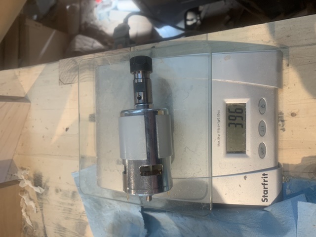
Hey All,
First time posting on here, excited to dip my toe in the water with one of these machines! I had actually printed everything for the burly, and was going to just build that machine but when I saw this one uses the 10mm belts I was sold and am in the process of making the primo parts. I’m planning to build a 24x24x3 working envelope machine. My garage/workshop is fairly well equipped but nothing cnc to date, so this will be fun, I really like the concept. Not building it to do anything specific, mainly general shop project stuff, maybe making guitar parts, who knows! I might put a build thread together but I have 3 kids between 6 and newborn, so that kind of time is difficult to come by…
Welcome to your perfect get-away-place! I have two kids under 5, and spend too much time in here and with tinkering. Some would say it’s stretching it, that I should relaxe more, or spend more time taking care of house and family. I find this rabbit hole a perfect place to keep my mind on something else for a little while - makes me more happy in general to have something else to think about as well!
I have 3 under 4yrs. Nothing like tinkering with one in your arms and the other 2 around your ankles! hahahaha
The trick is to use an ergo carrier, so you can have both hands free to tinker!
I do have a technical question regarding Primo - is there any reason I can’t use burly feet to build a Primo? I can print new feet of course but I’d rather not make new ones if that’s not necessary.
Burly feet will work fine. New builders won’t generally be buying any #6 hardware but it just holds the bottoms of the legs so it should be fine. I might have kept my feet but I wanted the colors to match and I was upgrading from “C” to “J” so that’s obviously an issue.
Great, thank you.
For those looking for stainless:
This stuff is shiny. I don’t know why it or shipping was so cheap. It did take a week and the tracking number they gave me was funky, but for the price… (Verocious motorsports) - I found them thru Amazon and looked them up direct
Started printing parts for my first MPCNC (or any CNC) this week, core finished earlier today! I ordered some stainless and I went to order my kit last night and SOLD OUT!!! I was holding out hoping for Rambo or Archim to be back in stock but was just going to order with the mini… Any idea on when Primo Kits will be back in stock??