Would aluminium foil work?

Edit: Holy hell, that took me almost an hour to write. Maybe don’t worry about reading it unless you’re interested in a slightly rambling explanation of the basics of EMC/noise.
No ‘big inductor’ is truly ever just a big inductor. There can also be a lot of inter-winding capacitance so I think you’ll be surprised just how ‘non inductive’ that coil is at even modest frequencies, given that it’s basically wound as a DC inductor.
It also depends on what you mean by there being no high frequency ‘through’. Probably not a whole lot of particularly high order frequency components in the current, but there normally wouldn’t be anyway. There will definitely a lot of high frequency voltage, given that the entire switching drive voltage will be appearing on the terminals. There will likely be quite high frequency ringing on the switching nodes (which is all of them in this case), which will then in turn lead to high frequency currents through the motor and coil parasitic elements.
Depending on the capacitor, this thing KILLS switching elements. That capacitor leads to a big pulse of current during switching, which is when the elements are going from off to on, so usually corresponds to the switch being in the linear state during transitions. Typically if you’re adding capacitance here, you’d be doing so with a resistor in the way to limit that current, or an inductor, which means that you then have a tuned element that needs to match the frequencies being suppressed. That’s basically called a snubber, at that point.
Adding inductance will reduce ripple current, which I doubt is the issue here, but it won’t likely do much more. Even if you added the same inductance as the motor (which is a pretty big inductor to add), then all it’d do is halve the high frequency component, if considered as an ideal component. In reality, maybe not even that. It may change the frequency somewhat, but unless you’ve got a clear starting and target point, just changing things isn’t usually considered a win. Maybe in this case it may work, though.
I don’t think you’re likely to hit a high Q resonance like that. More likely is that all systems ring on the switching edges and it’s some other aspect that makes it more of a problem for some people. Component tolerances, operating temp, cable routing, other background noise sources combining in the same bands, something like that.
You’re not that far off with all this reasoning at all, it’s all ‘close but not quite’, which is impressive.
EMC control ferrites/beads and inductors are similar on the surface but extremely different in behaviour/application. An inductor you typically want to be predictable in its complex impedance over a given and relatively low frequency range. A ferrite (which is an ambiguous name in itself, because most inductors still use a ferrite core) when used for EMC is typically an extremely non-linear component, with minimal impedance in the pass band and a rapidly increasing inductance/resistance in the higher frequency ranges where you want EMC control. As such, the behaviour will be very different.
So, the thing with EMC, especially at lower frequencies and ‘near field’ considerations, is that you can get either E field or H field coupling, which is electric field (voltage) and magnetic field (current). At higher frequencies or in the far field then you can look at it more as transmission/reception and things being antennas, but here it can be thought of more directly as those two fields. A differential voltage between 2 conductive parts will have an electric field between them, also between those parts and ground/earth. A current flowing in a conductor will have a magnetic field surrounding it. Both of those fields will couple into adjacent elements and induce what are usually unwanted currents/voltages in response. That’s basically all that ‘noise’ and EMC issues are, fundamentally.
In this case, the motor controllers are switching at around 40kHz into what is basically a relatively high value inductor in order to maintain a DC current. So in terms of current, we’ll have the DC component and then also a much lower magnitude 40kHz ripple component on top of that which will look like a triangle wave. Ignoring any of the parasitics, that will give us just the DC component of the magnetic field and then whatever the much lower magnitude triangle wave decomposes to. That DC component will also be varying with movement, but the step rates are slow enough that I’d still just consider it DC.
Then there are the switching nodes. The output terminals of the motor controller can only ever be at Vmot or 0V, but they will be switching between those two points twice for every 40kHz cycle. So each motor driver output, and consequently the wire out to the motor, will look like a square wave between Vmot and 0V at varying pulse width, but also with the edges of that square wave being anywhere between 10ns and 100ns, depending on the device. Those fast switching edges decompose into some quite high switching frequencies that are also unfortunately brief pulses at varying intervals.
So that’s showing that in this case we have a relatively benign current waveform and what is probably a particularly nasty voltage waveform, so anything radiating/coupling from the motor wires is likely to be an E-field issue. Anything that we do to limit how much that appears on the wire itself will need to either reduce those voltages or slow down the edge rates by filtering or absorbing the higher frequencies. A ferrite, for instance, doesn’t actually do anything to voltages because it’s effectively an inductor, it works by becoming lossy to any magnetic fields that couple into it. Similarly, putting a capacitor on a line with fast voltage transitions (say at the motor terminals) can actually make the situation worse because then when the voltage goes through its state transition, it will also have higher pulse of current (and associated H-field) to go along with it, and unless the capacitance is enough that it slows the switching edge rates down, it won’t have done anything to the E-field because the voltage hasn’t changed. It’s very hard to do anything particularly ‘filter-like’ on a low impedance line for this exact reason.
On the other hand, there are situations like the power supply for those motor drivers. You have a situation where the voltage to the motor driver doesn’t change, but the motor driver is drawing big square pulses of current out of the supply rails while it is in certain states in order to supply those to the motor. There’s no major voltage change (maybe just a little because the capacitors aren’t perfectly zero impedance), so there’s no major E-field concern there, but there are big square pulses of current which will cause H-field issues.
In terms of mitigation, in general currents and H-fields radiate/couple according to their loop area. More loop area means more flux at the same current, so minimizing loop areas helps to avoid both radiating noise and picking up noise. That’s one of the reasons why twisted pairs work, they keep that loop area predictable and low. The other way they work is by constantly rotating the loop so that, in a bulk sense, the magnetic field produced/received will cancel. The other option is to fully enclose the conductors in a conductor so that the magnetic fields generated are ‘shielded’, basically by creating current flow in the surface that creates an equal-and-opposite magnetic field, cancelling it out. The conductor needs to be thick enough so that all those currents are on one surface of the shield, otherwise the currents themselves will cause a field external to the shield.
In terms of mitigation for E-field, that’s slowing down edge rates to reduce the magnitude of the higher frequency currents. A lot of carefully designed transceivers (such as higher end CAN and RS485 transceivers) have slew-rate limiting to accomplish this. It’s common to slow down switching edges in power converters to trade loss for lower emissions to meet EMC targets, etc. The other thing is to limit the area of the conductors that are at those higher frequencies. Having a square wave and filtering it to a DC signal at the source means a very small area that’s being switched, while the rest is at DC. Having that same filter at the ‘sink’ end of the signal means likely more area (the conductors) that are at switching voltage, so more radiation from that. You can also shield this by enclosing the entire thing in conductor and connecting that conductor to a ‘quiet’ voltage. The inside of the conductor will have currents flowing in it due to the induced field, but the outside (providing it’s thick enough, again) will appear to be at the quiet voltage and won’t radiate.
Fundamentally, almost all filtering/EMC control measures are doing one of a few things. Limiting the magnitude of the unwanted fields, preventing the unwanted fields from radiating, or controlling the unwanted effects of the unwanted fields. A capacitor on a power supply line acts to limit the current loop of any fast signals. A filter on the output of a device acts to provide a series reactance which limits the current generated by a fast switching edge and a shunt capacitance which ensures that the limited current generated is kept within a small current loop and doesn’t generate a large voltage. A shielded cable or enclosure acts to confine those fields. A filter on a receiver is providing a series reactance so that any induced voltage from stray E-field doesn’t create high currents and then a shunt capacitance so that any induced currents from stray H-field don’t create high voltages. Things like ferrite beads are just another way to create a shunt reactance that is low impedance at low frequencies while being high impedance at high frequencies.
This post is way, way too long and I’ve completely lost the thread of my point, so to take it back to fundamentals:
A ferrite bead on a motor line won’t do much because there likely isn’t much high frequency current content, certainly not in the motor current. It may help to damp any ringing due to parasitics, though. A capacitor on the motor line won’t do much because it’s low impedance so will just increase currents without filtering. An RC filter or similar on the motor line would work if it was at the driver end, but would degrade the performance of the motor controller too much to likely be worth it. That leaves us with shielding/screening those conductors.
A ferrite bead on the LCD lines may work because any capacitance at either end will cause the induced voltages to become currents which will become ‘lossy’ in the ferrite bead. A capacitor on the LCD lines would also work, especially in conjunction with something like the ferrite bead, because it will ‘sink’ those induced voltages/currents to earth. The capacitor works to reduce voltage here because the induced voltage is likely very high impedance, so it can’t keep ‘driving’ that induced voltage into a low impedance, if that makes sense.
4 Likes
Maybe, but it’ll depend somewhat on the thickness.
There’s a concept called ‘skin depth’, which is basically how deep the currents induced in a conductor will be. Skin depth decreases with increasing frequency and higher conductivity materials. You need a conductor that is several times thicker than skin depth, otherwise the shielding process causes currents to flow in it that just radiate out of the other side. Think of it like having light blocking curtains. A wafer thin layer of material won’t do much, it’ll get better with thickness until it’s thick enough that extra doesn’t matter. Aluminium foil is basically a net curtain until you’re way, way high in frequency. The idea would be a copper pipe, but that’s bloody hard to work with so we go in two directions. One is when we need low frequency stuff then we need to keep it thick so we go to braided conductors in order to make it usably flexible. As long as there are no huge gaps (relative to the wavelength of the signals), the braid still works effectively, similar to how mesh can make a ‘faraday cage’. The other is that when we need really high frequency that would leak through a braid, then we make it out of multiple wraps of copper foil. When we don’t know what we need then we do both, braid for the low frequency and copper foil to catch anything that would ‘leak’ through the braid.
Aluminium foil is 0.2mm roughly and the skin depth at 1Mhz is 80um. So 200um would be 2.5 skin depths, which is enough to do a bit, but not ‘that’ much. At 10Mhz it’s 26um, so 8 skin depths, so it should be decent there.
So yeah, actually, it should work better than I expected. You could try wrapping the motor cables in aluminium foil with a stripped wire in between the layers as a ‘drain’, then connecting that drain wire to the chassis somewhere near the main PCB, or putting it under a mounting screw.
5 Likes
I’ve fixed display problems on old 3d printers (Lulzbot AO-100s and AO-101s that were being used at the local makerspace as a print farm) by wrapping the ribbon cables in QQB (silver coated copper overbraid) and tying one side to power supply ground. So a foil covering as a ‘fix’ isn’t unheard of and is probably worth at least an attempt.
The QQB was surplus stuff I had in my junk collection. But I bet wrapping in foil with a drain wire as you suggest would have been equally able to address whatever was wrong with those old machines.
Edit to add: I also wrapped the QQB in kapton tape as I was worried about the potential to short to things if the cables were disturbed as there were lots of hands on those makerspace printers.
4 Likes
Yeah, braid + heat shrink is a pretty common EMC troubleshooting step. I’m not a huge fan of Kapton in that environment because it pierces/tears super easily. I also found out the hard way that it’s temperature tolerance is good, but coupled with being reasonably flammable!
Yep, Kapton is a bad choice due to flammability concerns. But tempting when you have rolls upon rolls of expired tape at your disposal. And, weirdly, it was used for a while on hotends to hold thermistors securely in place.
1 Like
Yeah, it’s an odd one, that. Definitely know the feeling of using it for everything when there’s plenty around. That’s how we ended up discovering the flammability!
I guess at least with a hot end, if it’s hot enough to light the kapton, other stuff has already gone truly, terribly wrong…
Firstly, thank you for all the electrical engineering knowledge/thoughts!
For less flammable strain-relief/protection, would you use regular interior/exterior silicone, or high temp silicone gasket maker (maybe formed using temporary PETG printed mold, maybe with release agent) or something else?
Some context… Am looking for quick/easy way to improve how my CAN bus wiring connects to the EBB 36, until if/when an updated carrier design is available with strain relief mount(s).
Not sure what you mean by using silicone for strain-relief and protection? Are you blobbing it onto a connector or something? If you’re trying to keep a connector mated, I’d normally either swap to a connector with positive retention clips or I’d just keep the cable strain relieved near the connector with cable ties.
At work we use heat-shrink for bulk insulation. If you need water tightness or strength in tension then glue-filled heat-shrink works well. Heat-shrink also provides decent mechanical protection, although normally that’d be combined with careful cable routing and clips/cable ties to retain it in place, as well as things like rubber or plastic grommets or cable-glands for going through holes in sheet metal etc. Short lengths of flexible conduit for larger cables, often in orange for HV stuff etc. Fibreglass braided tube can also help provide mechanical protection/insulation where high temperatures occur, but it’s a bit of an annoyance to work with.
1 Like
Edit: Sorry, I’m going way way off the MK4 topic, and MK4 wiring issues. Moved my question about non flammable strain relief/mounting materials here.
1 Like
Thanks again for the in depth explanation, I am learning quite a lot.
Today, after the print finished, the screen came back with inverted colours. It did that once before but I didn’t draw the connection then.

I now ordered ferrite. ![]()
1 Like
First of all, thank you for the in-depth explanation. I am reading these descriptions closely and I feel like I am leveling up.
To clarify one thing, when I was speaking of capacitance at the motor, I was meaning accidental, parasitic capacitance across the coils or between the wires or into space, not added capacitance. The path I was imagining was the current to charge the parasitic capacitance, i.e. a tiny charge but very fast that results from the sudden voltage change. But I’m now convinced that magnetic coupling from this brief current is not very likely, especially with the twisted wires.
There is one thing that doesn’t quite align with what I thought I knew about ferrite beads. You mention they block high frequencies and pass low frequencies, but what I thought was that they block common-mode signals and pass differential signals. (For a ferrite bead on a single wire, none of that matters since there is no differential signal on a single wire and I was basically going for an inductor with less soldering.) Technically a ferrite bead should block common-mode current, but at high frequencies blocking current also attenuates voltages (according to my model of a transmission line).
Which I guess leads to the last part that I’m not understanding, which is why inductors near the driver would not also slow down the E-fields. With zero parasitic capacitance and zero capacitance to free space, the voltage can change with zero charge movement, i.e. no current (mathematically speaking, outside of reality). In this scenario an inductor would have no effect. But with some parasitic capacitance and some (unintended) capacitance from motor wires to LCD wires, a tiny amount of charge is needed to raise the voltage and some of the charge goes capacitively over to the LCD wires.
If the charge can be given ‘inertia’ by adding an inductor, then the same E-field and the same charge will still be sent over to the LCD wires, but slower, and hopefully the impedance on the LCD side is low enough that it can absorb the slower injection of charge without too much of a voltage disturbance. Whereas the same charge injected very fast produces bad voltages because the LCD side doesn’t have super low impedance. This would assume that the added inductors have low parallel capacitance so the fast edge can’t bypass the inductor.
Am I focusing on the wrong elements? I am reducing the E-fields to a capacitor between the motor wires and the LCD wires and maybe this is an error?
I think you understand very well but just to make it super explicit, here is a recap of what I am thinking:

Let’s say the motor M1 is a constant-current device over the timescales we’re considering. Either the current is being pushed by VMOT through S1 and motor current is slowly increasing, or it is coasting through D1 and the motor current is slowly decreasing, but that’s not a factor in what we’re considering.
C1, L1, and C2 are all parasitic elements with small values that occur accidentally. My earlier concern was L1+C1 inducing magnetically into the LCD when S1 closes suddenly but that’s no longer what I’m worried about.
Now I am looking at C2 and the fast voltage change from S1 dumps some charge into the LCD. It is perhaps a small amount of total charge but if it is very fast it might still be more than the LCD can tolerate.
The question is if we insert L2 in series, could it not dramatically slow down the charge that gets dumped into LCD1/LCD3? Or would it not have the beneficial effect that I am expecting?
Ah, right, that’s my misunderstanding, then.
My apologies for the minor nitpick, but I find it helpful to avoid thinking of it in terms of ‘blocking’ signals, so much as that they have lossy reactance to certain signals. Whether they are attenuating common mode or differential mode depends on how they’re attached, so I may have misunderstood something there. If you’re talking about a large clip-on ferrite over the entire wire bundle, it will indeed only be ‘visible’ in the common mode current path, which would be whatever current is created from the common mode voltage of the stepper driver returning through the stepper coil parasitics via the chassis etc. Probably not a whole lot going on there, so I probably wouldn’t bother.
They can also be clipped onto individual conductors, in which case they’ll act on differential mode signals, while being mostly invisible to common mode, at least at higher frequencies. It can get a little awkward here because with 2 lines having an imbalance in the reactance, you end up with somewhat of a differential-to-common-mode and common-mode-to-differential transform occurring. (That’s one of the reasons why balanced communications interfaces like RS485 are as noise immune as they are and why any filtering and termination on them needs to be carefully balanced.)
Anyway, aside from that, it’s quite common (and indeed preferable) to use a ferrite bead as a tiny passive in place of an inductor when filtering for EMC. An LC filter typically has a transition band where it has a resonant point and very low impedance. A ferrite bead avoids/mitigates that because the places that it has high reactance it also typically has high resistance, leading to the Q of any particular resonant point being low. The downside with that is that ferrite beads are typically far more annoying to spec and are best used at much higher frequencies. The alternative is using something like an RLC where there’s a resistor as well which works to set the maximum Q that the LC filter can have and keeps it from being particularly low reactance at resonance.
I don’t think of it that way in terms of EMC. We’re typically in the near field and not really propagating like that. Transmission line theory works best in lines that are a wavelength or longer and relatively predictable. With EMC we’re dealing with a messy stew of different parasitics and often in the near field. It would surprise me if the frequencies of concern here are much beyond 10-20MHz.
You’ve got it in one, though, I think you understand the basic physics, just not with the correct scales. What you’re suggesting is to make a filter from an inductor and the wire/coil parasitics, which may work, the problem is that what’s your target corner frequency, how big are the parasitics and therefore how big does that inductor have to be? Assuming 10 pF of parasitic and wanting a 1MHz filter, that’s a solid ~2 mH of inductance. You’re unlikely to get a 2mH inductor that keeps being inductor at 1Mhz, let alone beyond that, let alone while also being rated for several amps RMS, so we’re already into ferrite bead territory. A ferrite bead and a capacitor would likely make a filter that can get those edge rates down, but you’re never going to have a ferrite bead that’s good enough at low frequencies to avoid the extra current at switching edges and extra power dissipation in the drivers, so you’d also need to add an inductor or resistor for that. At that point you’re adding so much unknown reactive load onto the output of your drive inverter that you’ve gotta be very careful about how it performs under that load. My day job is basically to make inverters that don’t look that dissimilar to the output of a stepper driver that need to handle a wide range of quirky and irritating reactive loads (except at nearly a kV and several hundred amps) and it’s very easy to get into trouble here with even relatively minor changes. I suspect you’d smoke a few drive MOSFETs in the testing process here, for sure, while potentially never actually finding a happy operating point that solves the underlying issues.
I don’t think so, that’s basically what it is. I think the issue is a matter of scales and impedances.
Basically, although from looking at the TMC2209 datasheet, it appears that it also has a state where it deliberately inverts the applied voltage on the coil (it calls this ‘fast decay’ mode, as opposed to slow decay mode where two low-side or high-side FETs are on, equivalent to your ‘coasting through a diode’ description).
I’d say that’s a fair assessment in this simplified view of things.
It will indeed be small, but it will depend on what filtering is on the far side of the LCD and what the impedance is at that frequency. This is where things can get rough, because frequencies that would be considered high-order harmonics or switching noise in the power electronics world can be well within the actual operational frequency range of a digital comms link. A 40kHz power converter with 50ns edges is producing quite a lot of noise in the ~1-10MHz range on every transition, which is probably around the data rate into the LCD. If the circuit at the LCD end is just a bare input pin, that may only have a few pF of capacitance on it and nothing else. Thinking of that as a capacitive voltage divider with 1pF from the +/- 12V signal to the LCD input and then a few pF from the LCD input to ground, you can see how we might induce a couple of volts on the LCD pin. You can also mess up digital signals with far, far less than a couple of volts. The timing might need to be absolutely perfect, but if you have a relatively slow digital edge, a brief spike of a few hundred mV at exactly after the digital edge has passed the switching threshold voltage, it might be enough to cause an extra spurious edge especially if the input doesn’t have much or any hysteresis (amusingly, this input hysteresis is yet another way that things like RS485 transceivers add noise immunity).
I think I covered that above. It would, but in order to so you’d need a LOT of inductance because C2 is so small. Think of it like having a 100K resistor to ground. There’s a certain amount of current in it. If you want to halve that current, you need to add 100K in series. If you want to lower that current by a factor of 10, you need 1M in series. That is what makes high impedance signals hard to filter on their own. To get around this, you add extra shunt reactance. If that 100K resistor to ground now has a capacitor that’s 100R to ground at the frequency you’re worried about, you only need 1K in series to drop the current by a factor of 10. The tricky part is doing all of this with relatively high current signals and with a device that is measuring those currents.
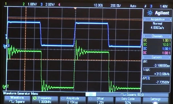
So, the other thing is that we can layer a little more complexity on top. That L2 that you’re talking about already exists somewhat in terms of the wiring inductance. L2 + C1 already make a resonant circuit. S1 and D1 also aren’t perfect components, they have their own parasitics in terms of series inductance, capacitance, parallel capacitance, all sorts. Any time the voltage at the node between S1 and D1 makes a sudden change, it likely have enough broadband signal to excite the resonance in L2+C1, which will cause the signal to ‘ring’. This will result in the voltage at that node not being just purely Vmot or GND - Vf(D1), it will look more like the green trace in this:
That is where things get nasty, because even a relatively small excitation can cause a lot of signal at a specific frequency. Where that frequency is will vary a lot depending on the cable path and random variables with how the things are constructed, which is why it’s not too surprising to see situations where some machines are worse than others, etc.
But there is one critical aspect to all of this. This discussion is talking a LOT about the mechanisms behind this and you’re focusing heavily on how to stop the EMC issue occurring in the first place. That’s the ideal option, when possible, but it’s also usually the least practical in reality. In the real world, we’re far more likely to move to the next steps which is to contain the bad, protect the sensitive parts from the bad, filter the bad out of the sensitive parts.
Containing the bad would be shielded motor cables. Easy but expensive, and surprisingly awkward to terminate the shield well.
Protecting the sensitive parts from the bad would be changing the routing of the LCD conductors or shielding those. That can range from easy (re-routing in some cases) to extremely difficult (shielding). It’s a big design change to go from micro-match connectors and ribbon cable to shielded conductors, likely needing an entirely different underlying comms protocol to make it viable and limit the total number of conductors.).
Filtering the bad could be anywhere from simple (RC filters on each input) to difficult (hysteresis on inputs, balanced inputs).
Hopefully you can see some themes here and, if I’ve done my job here right, you can perhaps see how some of the suggested extra components on the pendant are giving you a few options in case you ever run into any of these situations… That’s a lot of what the difference is between pro and amateur level design, honestly. It’s often not about the overall complexity. Complexity is often a vice, in my opinion, and anyone can easily over complicate a design and throw far more than is needed at it to the detriment of later needing to have something working reliable and predictably. Where possible, it’s much better to simply avoid the traps altogether rather than walk into them and then brute force your way out with metallic enclosures, expensive cables, additional components. The pro approach would be adding a few passives here and there where needed, choosing the correct logic series for the task with slower edge rates, using a buffer that has input hysteresis etc., all the while predicting where the issues will crop up in a later EMC test and making sure that there is already a set of steps that can be easily taken to not just fix the issue, but often to even make it possible to diagnose in the first place.
2 Likes
Thank you so much for your patience. I think I am starting to get it. I need to read through a couple more times to get all of it.
I will say that yes I was thinking of the big ferrite beads that clamp onto a bundle of wires, like you find on most VGA cables. I will have to read up more on the small ones for single wires.
2 Likes
I know that I’m not, but every little bit gives me a teensy bit more focus in the understanderscope.
I am so glad to have you blokes to call on! ![]()
2 Likes
Yeah, I typically avoid clip-on ferrites in anything other than truly last ditch efforts, but we do have a few of them around. The system I’m working on currently has a couple on the digital control lines to our MOSFET drivers because even a few pF of transfer capacitance in our isolators can see some pretty nasty noise when we have 900V/20ns edges.
We use a lot of the ferrite beads in 0805 size for up to a couple of amps on things like power supply lines because they’re a good way to add series impedance at high frequencies without causing LC resonant networks or adding resistance which leads to high losses and poor load regulation of the supply.
Progress: I redid the cables, one of the ribbons changed direction (don’t know how to explain it better), now they are parallel again. Instead of not showing the screen any more, I had the inverted colours. Better than nothing. Funny thing: After a reset it immediately had the right colours again (no power down, just reset). So it might be firmware also, maybe the screen could “reset” itself somehow. Don’t know. Not getting paid for figuring this one out. ![]()
/edit: And now it is turning off directly after booting… eeek… Something is really wrong here.
Lots that could be going wrong here.
All that it takes to corrupt that display is a little bit of a glitch. If you corrupt the data stream going to the controller, who knows what that gets interpreted as. I’ve seen displays go all kinds of wacky. One report I got from a community member at the local makerspace “The printer is now displaying in Klingon.” (Upon looking at it in person, it almost did look that way.)
Glitch power or blip the return side so things go undefined inside the controller in the display, and again who knows what you’re going to get.
It could also be something random like a batch of supplied components (displays) with a latent defect or damage from something like ESD. Maybe even a build/assembly error on the display board itself.
That’s uncommon with reputable suppliers but it happens. I got a batch of boards one time with a bunch of missing capacitors. Things happen.
It could also be bad contacts at the connectors, or any manner of EMI as has been discussed a bunch up the thread.
If you “flipped” a cable over, I’m curious if the keys are no longer aligned with the sockets for one of them. Are there keys on the display, cables, and controller? It probably got put in ‘wrong’ on both sides or your display wouldn’t be working.
Next time you have the printer open, can you get good close up pictures of the cables, connectors where the ribbons land on each side, and as good a picture of the front and back of the boards on the display and printer controller?
If it were me, I’d still try to make some kind of a conductive foil or conductive braid overwrap of those cables and then tie one end directly to the power supply negative rail with a good drain wire. I’d probably tie it on the controller side with as short a wire as practical.
I’m starting to wonder if there’s something about the fancy way the TMC stepper drivers manage current to the motors that contributes significantly to potential EMI/EMC issues with other components.
Maybe Prusa inadvertently has a design defect where some aspect of the system is susceptible to noise from those stepper pulses or electrical noise created in the control board by the stepper drivers .
Perhaps there’s inadequate filtering in that part of the controller design to prevent noise which affects other parts of the controller which then corrupt communication with the display.
Fiddling with the settings for the steppers might come into play at some point. Is it easy to turn of the “Stealth” (Quiet) mode in the Prusa firmware as a test to see how that impacts the system overall? Or even slow down the stepper speeds as a test. You don’t really want to slow down a printer with print speed as one of its’ key attributes. If it prints reliably without corrupting the display at a slower speed that is at least insightful to where the problem might be.
1 Like
I thought about that as well, that it might be the new Input Shaper Alpha Software, but in the forums this one fixed the glitches for some users, so I don’t really know. I decided to just try a few more times, am chatting with the support who can’t really help at the moment except to ask for pictures and am getting ferrites on Monday.
Not the connector. It has a notch, can’t do it wrong. ![]()
In my opinion, that printer is far too overpriced for that!! I saw something where this was happening on the 3s and they recommended gently stretching out the cable!!!
3 Likes