After a few false starts (3d printer blew up, printed XY plates with supports, unforeseen expenses, etc.) and a new 3d printer later, I’m starting to make progress on my LR4 build. I’ve been following the lowrider project since v2, but decided to pull the trigger with the LR3…actually I started printing the LR3 as LR4 was just coming online.
During the time of these false starts, I worked (and learned) on what I could such as learning CAM with Estlcam, watching Doug’s Youtube channel, and studying build instructions.
Regardless, I’m hellbent on getting my LR4 operational. It is no longer a little project…it is my mission! Thank you, Ryan, for the design. You should see an order for my next batch of parts shortly.
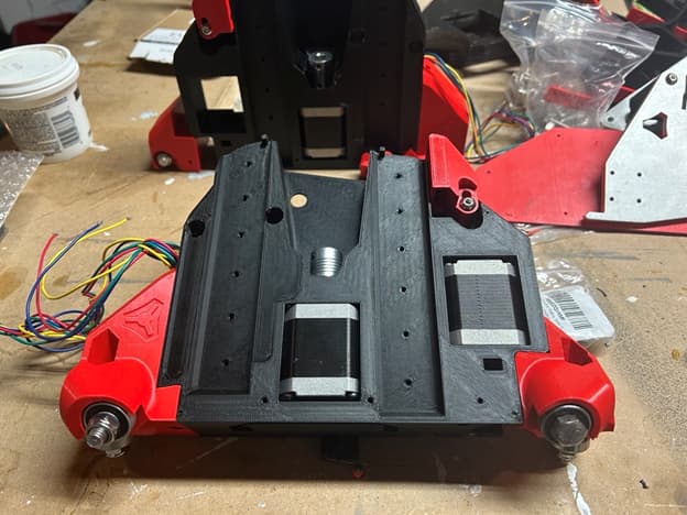
Cool, welcome to the party. The roller’s screws might be 5mm too long, at least the one I can see on the bottom left, it might collide with the rail clips. It also might not.
Thanks @DougJoseph! In addition to everything else, I’ve been designing (simple designs) flat pack furniture in Fusion 360, so my goal is to see those designs come to life.
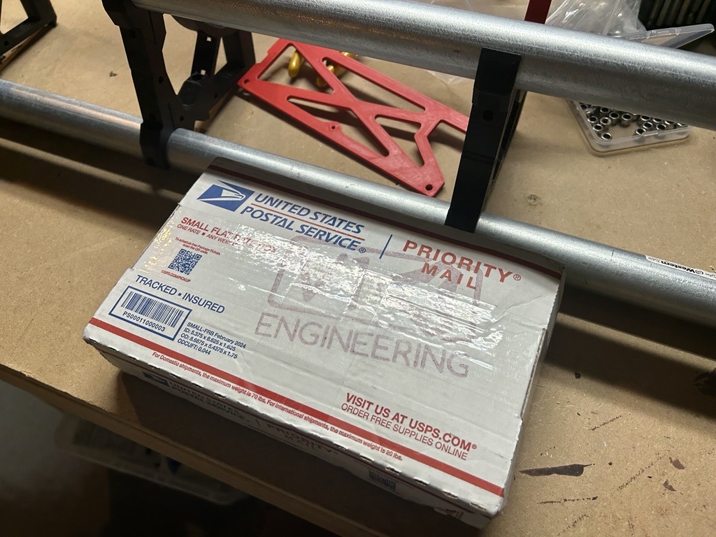
I placed my order for the last batch of parts. It has been confirmed that it is on its way. Thank you Ryan.
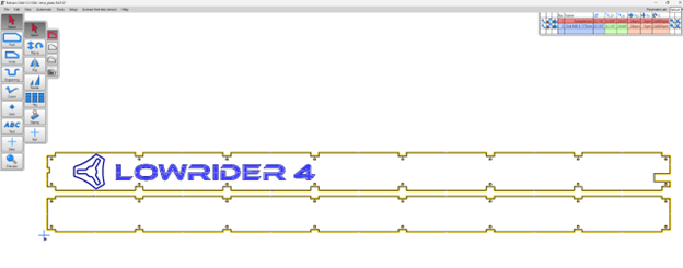
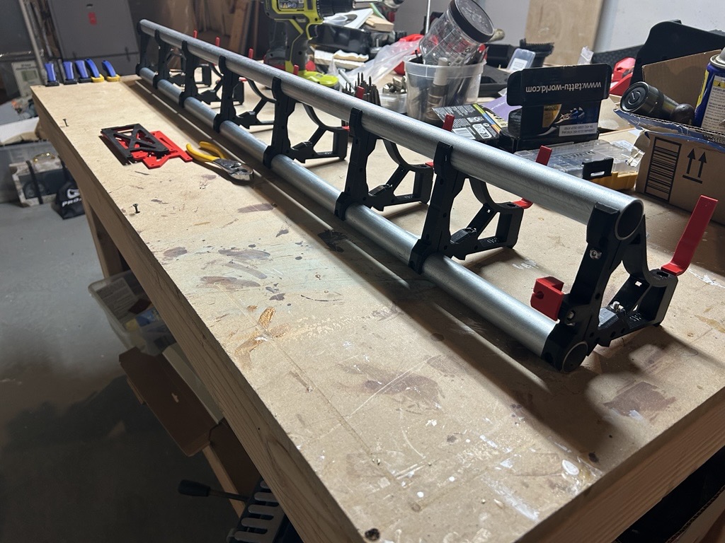
In the interim, I started working on the gantry by cutting the conduit and adding the nuts and bolts to the braces.
Question: My gantry is going to be longer than my length of table (Y). How am I supposed to cut the struts…as I’m assuming I won’t be able to cut them in the direction of X, correct?
Not without a clever bit of manoeuvring that involves doing one part of the cut, moving the workpiece relative to the machine and then running another part of the cut. It’s one of the reasons it’s strongly recommended to make Y the longer axis.
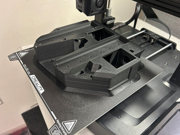
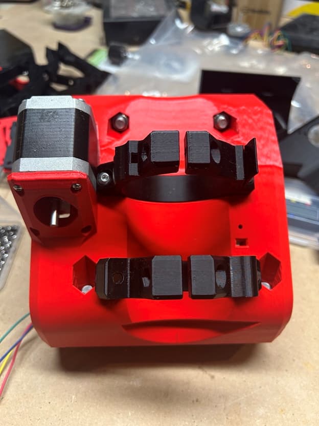
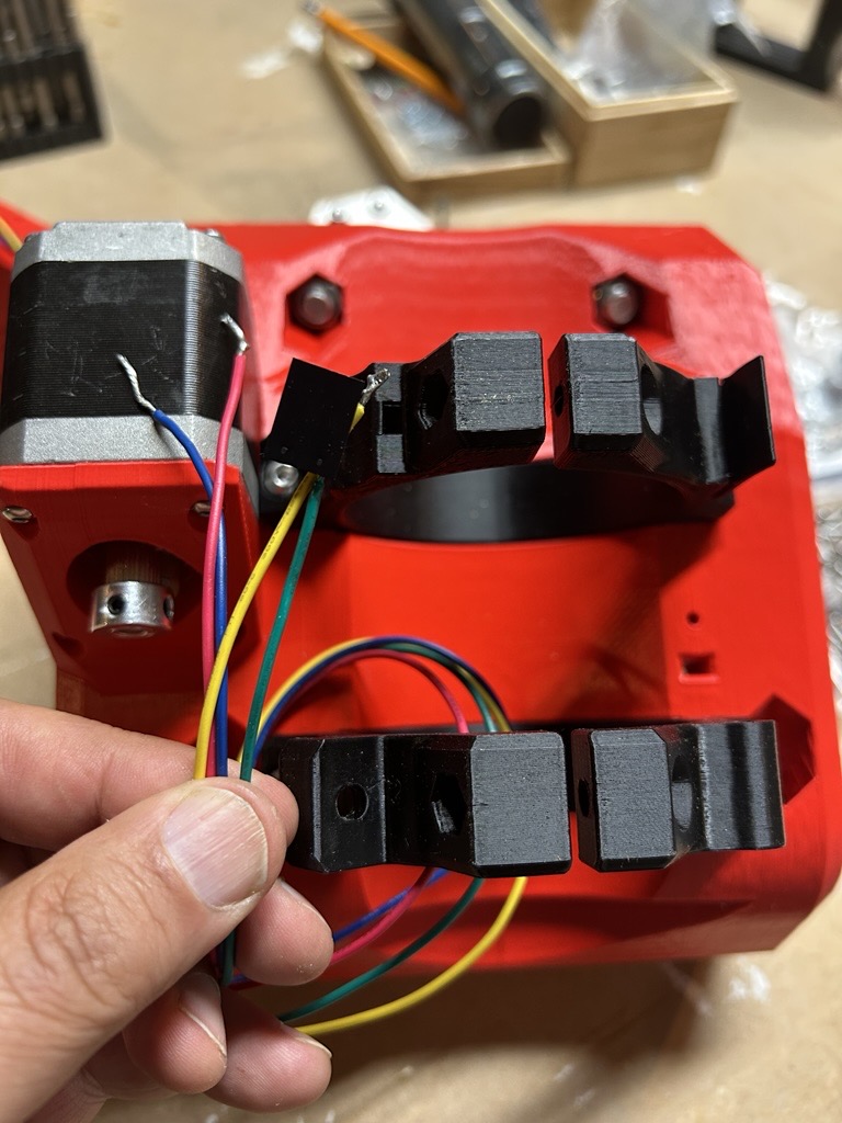
Second batch of parts arrived. I’m going to try to finish the XY Plates and Core Assembly this holiday weekend. I got the tooth pulley added to the stepper for the core assembly.
Question: My stepper motors are bare wire without connectors as they were given to me. I saw on YouTube how to isolate which pairs of wires go together by touching two wires and checking for stepper resistance. I have connectors and a crimpers, but I’m note sure how the pairs of wires goes to which pins on the connector? In other words, do the pairs goes together (next to each other) or every other (alternating). Sorry, I’m not an electrical engineer. I was CISC, so it is either 1 or 0 for me.
Usually the connector is a pair on each side. So if the pairs are A and B, the connector would be A, A’, B’, B. This works with polulu style stepper drivers such as those used on most 3D printer control boards.
If the motor turns the wrong way, you reverse one of the coils and it will go the other way, or take the whole connector out and turn it around.
Update: 5/30/2025
I’ve been busy lately with my kids end of the school year activities (soccer tournaments, band concerts, end of school year events), so I’ve only been able to work on the build 10 minutes here…20 minutes there. I’ve hit a point where I really need to focus on the electrical components (adding dupont connectors to steppers and end stops, testing that wiring.).
Somehow I lost one of the 20 Idlers/pulley…sigh…so a third batch of parts and accessories have been ordered. Not an easy project to do when you have a busy life!!
Hopefully, my next post will be a mostly completed project. I think I’ll focus on cleaning up my work surface and table.
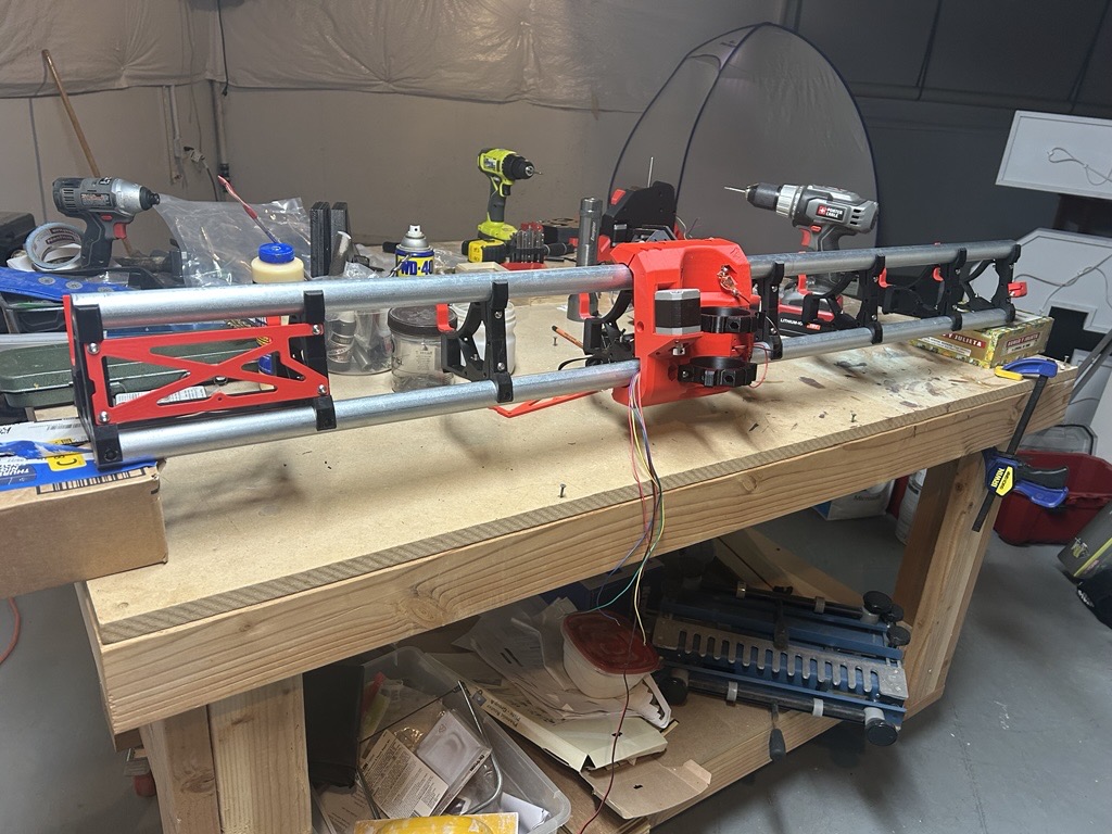
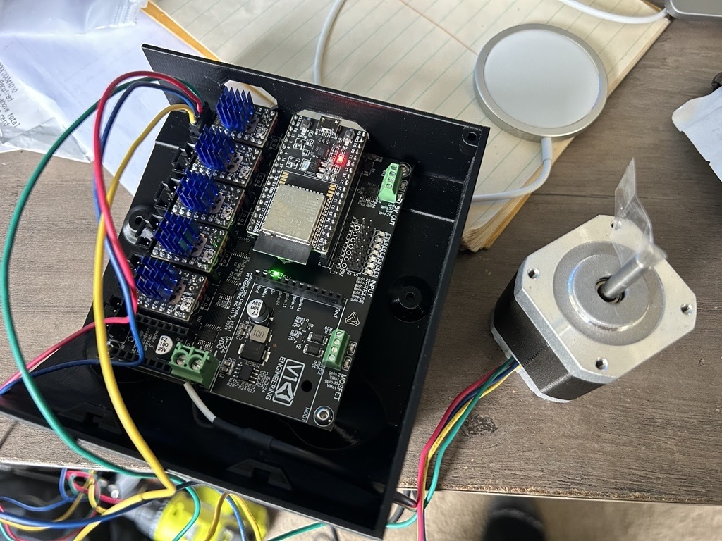
I took a stab at adding Dupont connectors to my stepper motors. After a little trial and error, I got them connected to my Jackpot and powered it on. Using the onscreen controls and I pressed the +100x button and it worked!!!
Question: If I press +x, which direction should the stepper rotate, clockwise or counter clockwise?
If clockwise, I nailed it on the first try.