The test crown, Has that built it so the best thing to do is start with the premade gcode that link takes you to, move the head to where you want it to start, with the head just above the paper, and then run the file.
The premade file resets the coordinates and move down 1mm to draw.
If that works great then try to replicate it yourself, and that includes setting up your starting gcode (G92…etc)
1st crown test. Failed to rcheck level after relocating my table in the garage and doing some clean up. Right side was low by about 1/2". Haven’t redid the test yet after leveling. Weekly rotations to spend time with my gf and not having my trailer ready just yet for transportation is slowing progress but i am so excited. In the meantime just trying to learn more beginner stuff.
Feeds and speeds, materials prep(use of oramask), bits (mainly doing engraving), design and do much more to learn. Don’t think this could be possible for me to find a new passion without V1 engineering and the affordability and just taking the dive to learn something new. So very much appreciative.
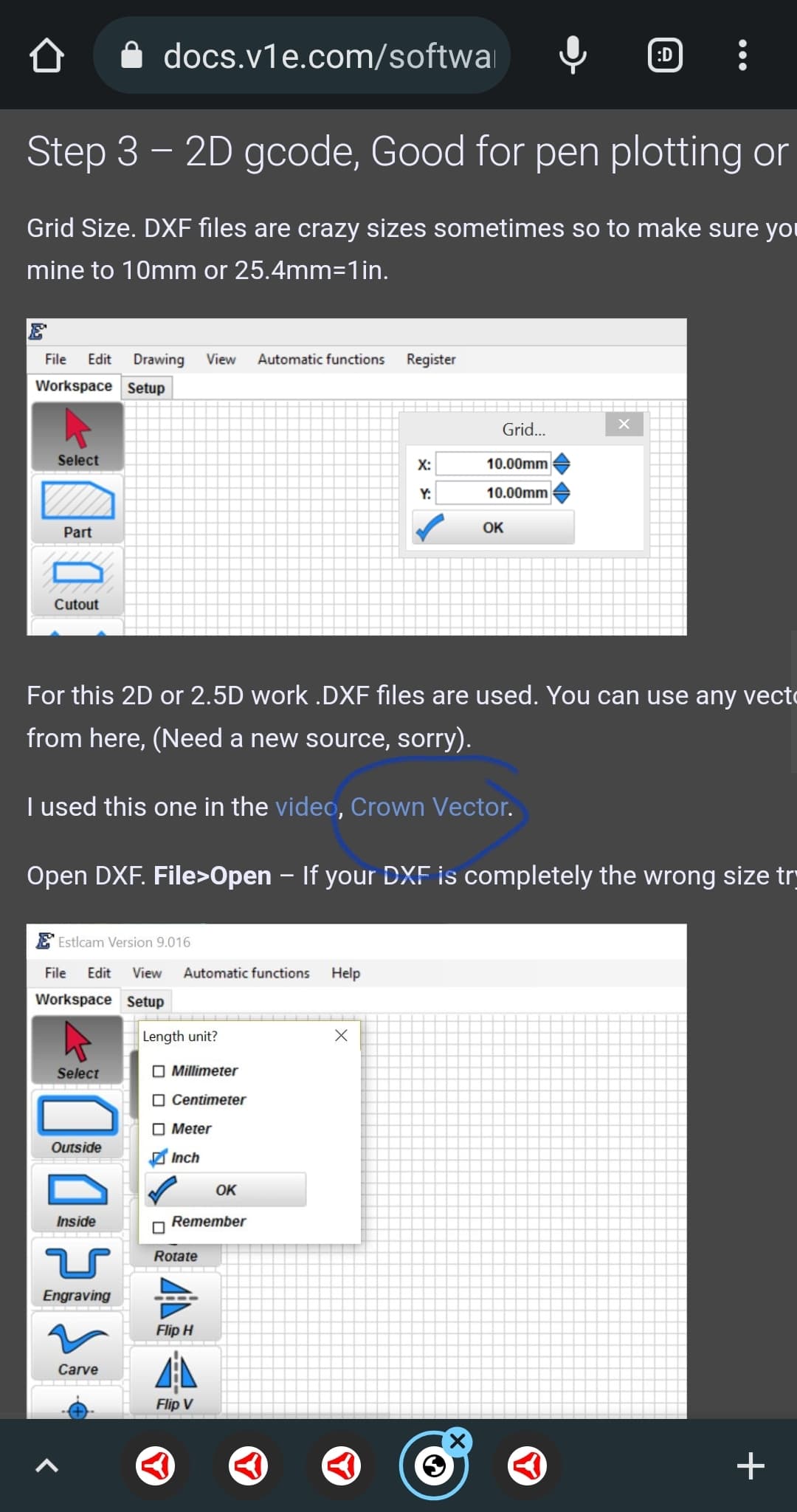
Biggest conflict I have just getting into woodworking and the world of being a craftsman is imperial vs metric and I loved math, love numbers, but do not want to go back to school to learn the metric system lol.
I use onshape for cad (they have a free for hobbyist license). It will convert for you. If you type “0.75in” in a box or “19mm” in a box, it will convert it for you.
There are advantages of both systems. Learning a little metric won’t kill you. You don’t need to go to school to learn there are 10mm in a cm and 1000mm in 1m. That is literally all you need in woodworking.
You can also use inches in Estlcam windows, and still have it spit out gcode in mm. I would not recommend using imperial in gcode. It just don’t think the juice is worth the squeeze.
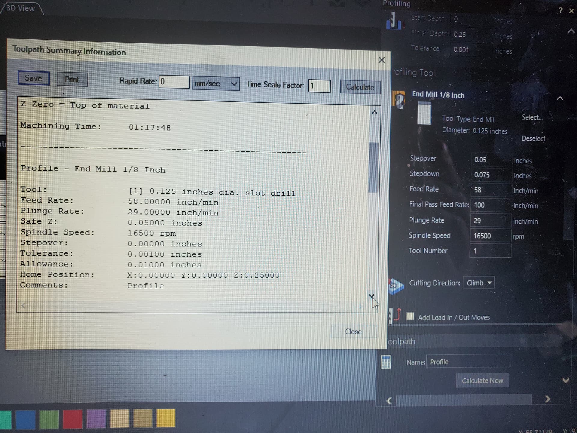
I am using Carveco (trial subscription) as leaning towards that for future use, and as I am learning researching feed and plunge rate I had a question. Is it accurate to say plunge rate is normally half feed rate. Also when deciding feed rate using a chip load calculator due to the chipload being different industrial vs manufacturing . Its best to take the average of both (industry + manufacturers)/2 for a more accurate chipload. Using
Also have Makita router dial set to 2.5/16500 rpm
Perform a test cut and after check 5-10 mins temp of router should be warm to touch not to hot. Also look for chips not fine particles
Chatter or RMP Drop= too fast feed rate or too low rpm
High pitch sound= low feed rate or too high rmp
Think I have a better understanding of everything. What is normal thickness for spoilboard?
Just needing to level my Z then ready to start cutting.
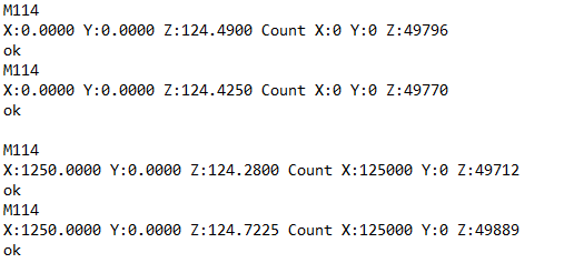
If I understand correctly take the average X-Min Z:124.4575 & X-Max Z:124.50125 subtract those 2 difference= 0.04375 then enter M666 Z 0.04375, M500 while it is at X-min since that moved the farthest. Test again and make further adjustments if needed?
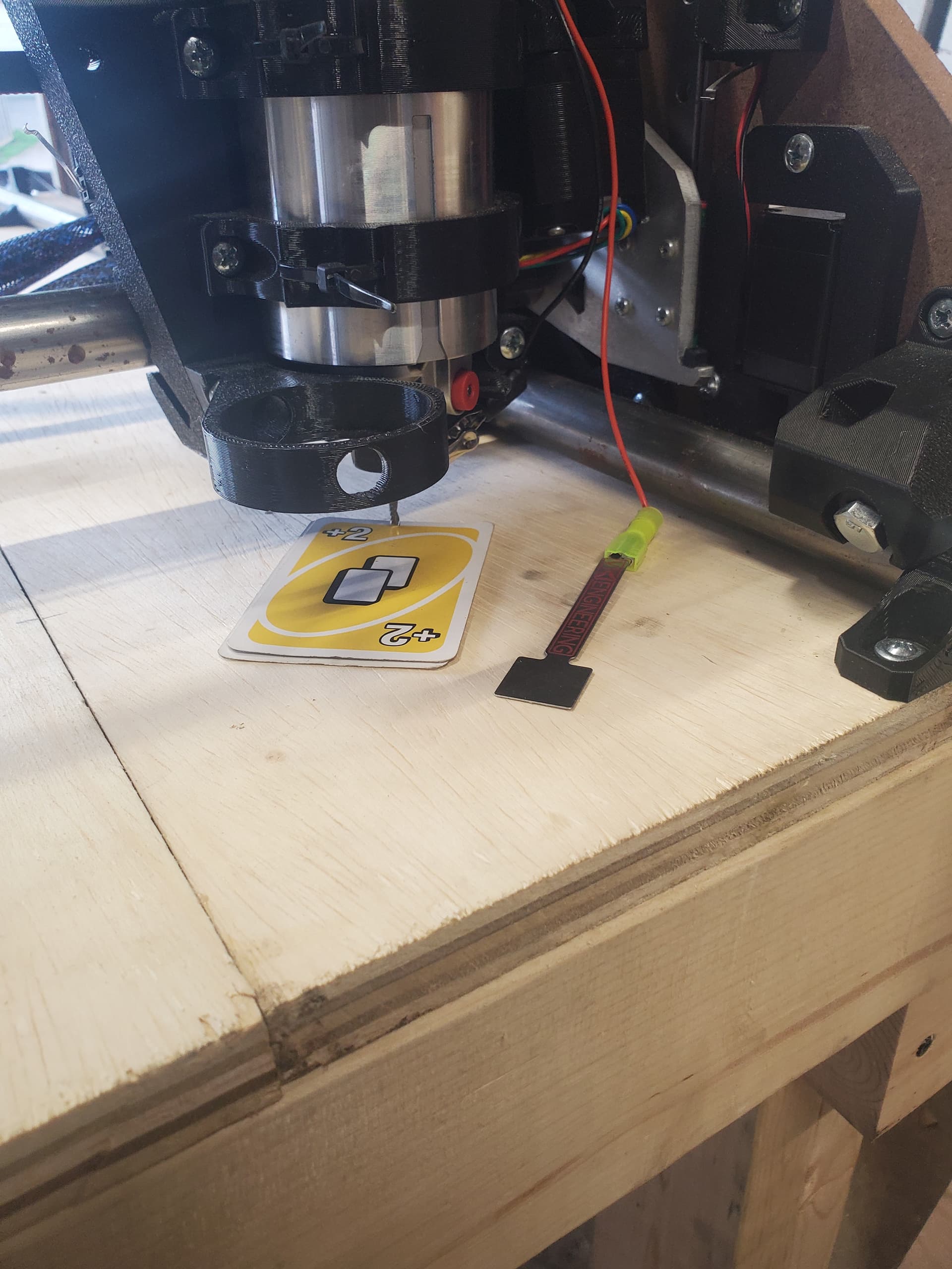
So not perfect yet but definitely a difference. Using Uno cards as spacers to keep Z from just driving down. From 0.101 in Uno card thickness to 0.022. I originally did M666 Z-0.044 on Zmin side Z min traveling the farthest. Just to ensure I understood the process I then reset to M666 Z0 moved to Z max side and did M666 Z0.06 and just increased until M666 Z0.1. Think i can go M666 Z0.15 and might be the sweet spot.
Fyi Uno card thickness is inches measured with calipers
Considering how M666 ended up being close maybe can just add thickness of touchplate and that would be your M666.
So which ever X side is higher take card thickness plus touch plate (0.5 mm or 1/64") after probing to lowest point and that would equal M666.
Original card thickness before M666 0.101" + 0.02"(rounded)= 0.12 would be M666 Z0.12
Was going to upload a video showing the probing but as it is a Mp4 file it’s not authorized. Tried converting it to JPG but to much clicking. Was going to ask what physical change if any would you notice when probing after M666. I see an offset on Z-min side vs Z-max.
They are too big. You need to upload them to youtube or another video hosting site and post the link and it will show as a video if the link is on a line of it’s own.
So went to home depot to pick up some 1/8 hardboard for struts. Grabbed from the 1/8th rack, took it to get cut to manageable size and find out at check its really 3/16th (got 50% off) Was planning to laminate it for 1/4th. Will 3/8th be too thick for struts. Should i just plane it to 1/4?
from my understanding if you want 1/4 struts you have to reprint all your supports bc they only do up to 1/8. its pretty tight clearance when the core moves over. somome did a remix for 1/4 on this forum. doug something I think.
6.35mm is a tight fit. If you get some M5 screws that are a bit flatter than the ones included in my kit you can go a bit thicker, then the belt and endstop start to get really close.
You should be able to mock it up and do a few really quick tests to double-check.