isnt 150mm longer than the linear rails?
150mm is 15cm, or 0.15 meter, so about 6"
That’s certainly longer than the travel on the Z axis, so I think I have my configuration wrong that converts rotation to distance. Here’s what I have:
[stepper_z]
step_pin: PF11
dir_pin: PG3
enable_pin: !PG5
microsteps: 16
rotation_distance: 8
endstop_pin: ^PG10
position_endstop: 160
position_max: 160
homing_speed: 10
I thought that rotation_distance=8 meant that each rotation of the motor moved the axis 8mm. I’m still learning this stuff. Maybe I have something wrong in the steps per rotation?
FWIW, all I had to do to “invert” my Z axis properly was flip the motor wires and change position_endstop=0 to 160, then save and restart Klipper. No compile, build, flash.
It’s my understanding (and i might be wrong) that rotation distance controls distance traveled and micro steps controls how precise the distance is calculated.
2 Likes
Looking at my config, it looks like I have my micro steps also set to 16, and a rotation distance of 4, but that is only because I have different pitched lead screws. The normal rotation distance is 8. What type of lead screws do you have? From V1E store or from another vendor?
Good to know how someone else has it configured. I’m pretty sure my lead screws were bought from AliExpress or Banggood around 2020. Ali has purchase history that far back, no lead screws, but I did buy some lead screw nuts around that time. Standard T8. Banggood has no old records.
However, these photos show (a) 4 starts and (b) a little under 13 threads per inch. Since 8mm * 3 = 24mm and 1" = 25.4mm, I’d expect 4 threads per 8mm, and a little over 12 threads per inch. Pretty much confirms that mine are standard.
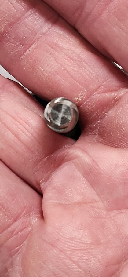
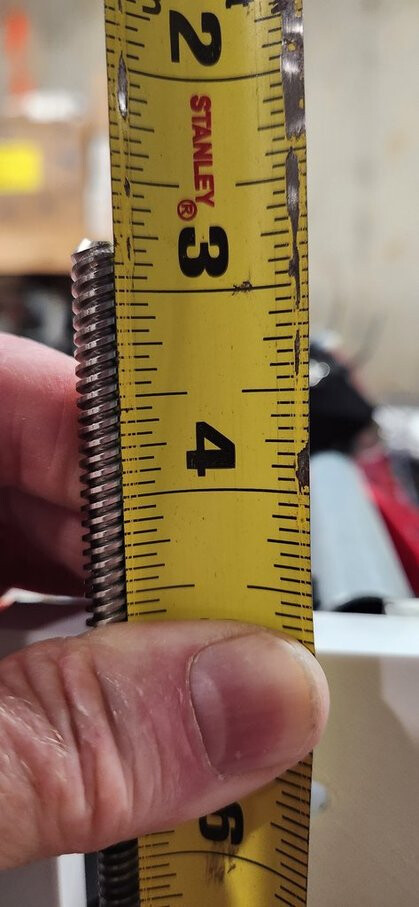
Next step is to measure actual movement when it thinks it’s moving, say, 10mm. EDIT: OR I can put a tape flag on the lead screw and check rotation angle for an 8mm move. Full circle means it should be right.
What’s your rotation setting for X & Y? @PKochZ71
Got it figured out! I had to add the configuration line
full_steps_per_rotation: 400
for all five motors. The default value without this line is 200.
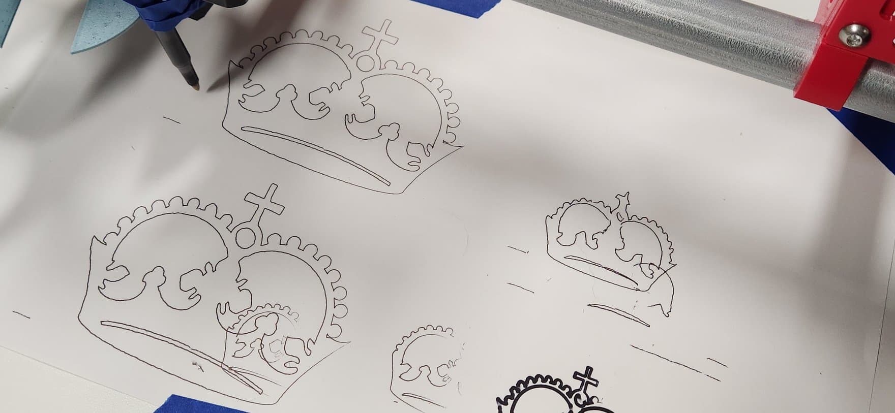
After that, I knew my crown would be 2x in size, so I redrew it – first one overlapped a previous (smaller) crown; second one is pretty clean, and I ran it at 1.6x normal speed. I’m pretty happy with these results now!
This is strange, though. I bought the motors from stepperonline via ebay in 2022. The Item Specifics section says they’re 1.8 degree (200 step) motors. I also see that what Ryan sells on v1e is a 200-step motor. Maybe I was shipped the wrong thing, but at least it will work.
Any downside to this? Seems like having more steps could make a program run slower, though Klipper may help here. Extra precision shouldn’t be a bad thing, right?
Klipper docs say:
rotation_distance = <full_steps_per_rotation> * <microsteps> / <steps_per_mm>
so maybe keeping full steps at 200 and bumping microsteps to 32 is the right way to go?
@PKochZ71 Do you have any config under [tmc2209 stepper_x] or other tmc2209 sections? Mine are currently blank.
Just like @adammay5, I’m trying to figure out my software toolchain now that the machine seems to be functional. As I said above, we’re in a house without Windows™, so Mac and Linux are my options. I had hoped to bring up a VM running Windows, but I see that Microsoft has pulled their images since the last time I did that, and I can’t get my old Windows 10 VM images to run.
So I started looking for Mac options, and I found this REALLY good video on using Fusion360 to go from DXF to finished product https://www.youtube.com/watch?v=OOT-AlpDDao and it also worked going from SVG to toolpath, but I’m not sure which stock post processor I need to use to create the gcode that Klipper will ingest. There are probably 100 options, including LinuxCNC and RepRap, plus tons of commercial brands.
Does anybody here use Fusion360 for their CAM? I’m running out of (free) options.
Turns out there’s an option for EstlCam post processing that produces gcode. I’m working out some Klipper incompatibilities, like the G01 vs G1 issue (added the macros for that - thanks, @jeffeb3 !) and tonight I did a partial dry run, no router, just the empty gantry.
It seems to be (mostly) working, but it’s now complaining that it doesn’t understand G2 or G3, which are arc/circle moves. I remember reading that arc/circle moves are a config option that has to be enabled, so maybe I’ll clear that hurdle tomorrow.
But for now, having it actually move along a toolpath that I created from the SVG file output for the basic strut, I’m pretty excited.
Are you using tmc2209? Are they communicating over usrt or in standalone mode?
The microsteps the drivers expect should match the microsteps klipper sends. If that is why you had to change to 400 from 200, that’s probably not a big deal.
Steppers lose torque at higher rpms. Some other configurations (like a 1 start leadscrew) would mean losing that torque at higher linear speeds. But it looks like you already checked that. And that wouldn’t explain your xy being off by 2.
I think you have your stepper drivers working in 32 microsteps. That should be fine. It is a little more work for the mcu. But on a 32 bit board, it doesn’t matter.
Using estlcam to make the gcode is my recommended way to go. There is a checkmark in the gcode output settings to disable arcs (g2/g3).
Thanks, @jeffeb3! I’m pretty sure my steppers must be the standard 200 step type, so yes, they must be in 32 microstep mode. I don’t have any Klipper config at this point for the 2209 settings, so I’m not sure what it defaults to but my movements are now at the right scale.
So when I mentioned estlcam, I meant that Fusion360 has a stock estlcam post processor, not that I’m able to actually use estlcam. I found the Klipper config to enable arc & circle processing, but I haven’t had a chance to test that yet.
And yes, I’m running Klipper on a Pi 3B+ and my controller board is an Octopus Pro 1.0.1, so I should be okay on processing power. I assume that Klipper on the Pi converts the curves to straight line segments and sends those to the controller board anyway, right? Or do those get passed through to the controller?
I haven’t thought about that before. The klipper protocol is pretty basic. They do that to make the mcu screaming fast and do all the development of complex geometry in the pi. So I would guess you are right there.
TMC2209s can be configured to ignore the uart pins and just run on the en/dir/step pins. If that’s what you have, then the current is determined by the screw potentiometer on the tmcs and you need to make sure that is set properly. Running in uart mode is much nicer because you can configure a lot more and klipper can get error messages. But standalone will work.
Trying to figure WHY the default settings for Klipper don’t have arcs & circles enabled – my guess is that the most common application of Klipper is for a 3D printer. I assume that the slicer would have already processed arcs into short line segments, so there’s no need to bloat the code with unneeded capabilities.
Dang, looks like I have another learning curve to tackle this weekend. (but it’s still fun!)
1 Like
FIRST CUTS!!!
I got the TMC2209 stepper config set to UART mode. That’s working great now. Before I attempt to cut my struts, I wanted to use the stock crown gcode file to do a simple engraving. To increase the depth of cut, I added a
G92 X0 Y0 Z3
command just before the carving starts. As-is, the file moves the pen down 1mm from Z=0, so this should give 4mm DOC, if I understand what it’s doing.
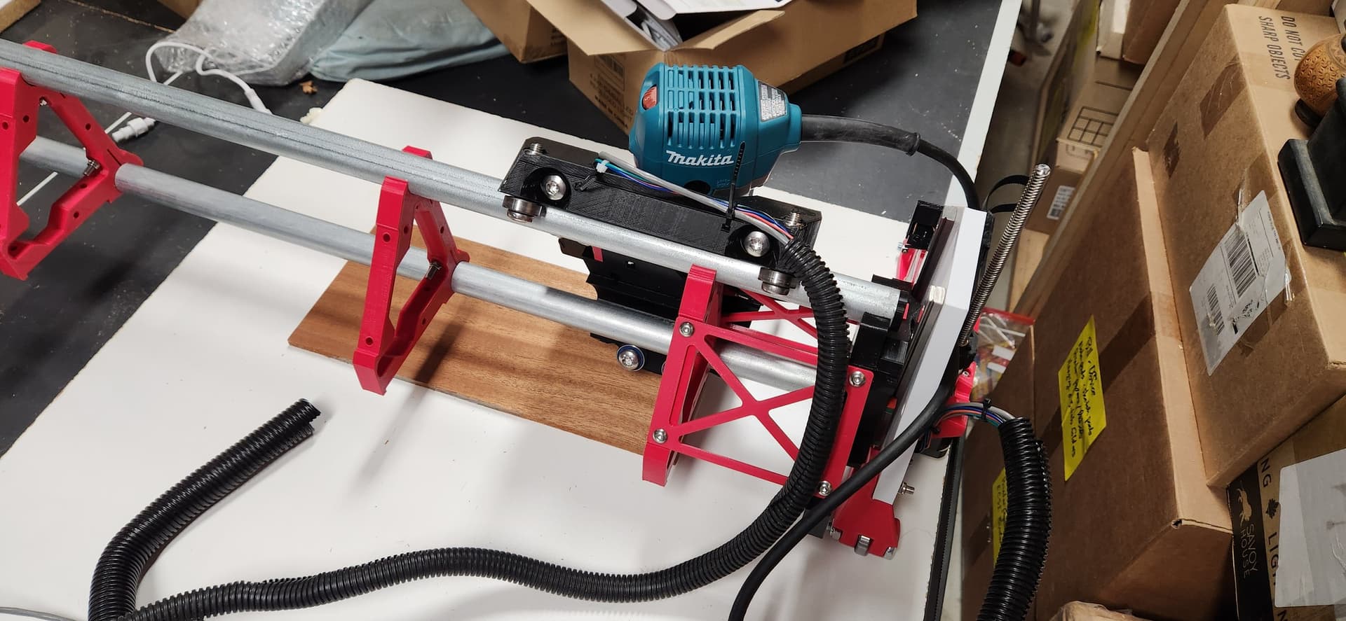
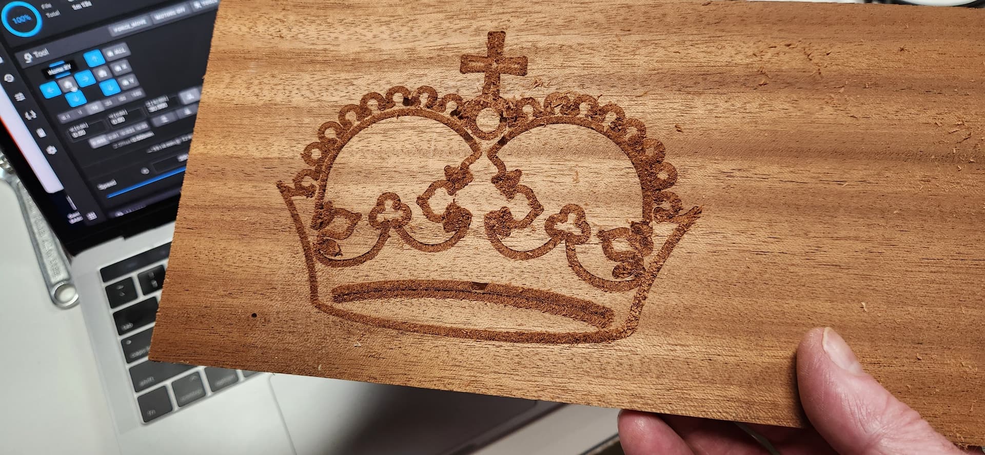
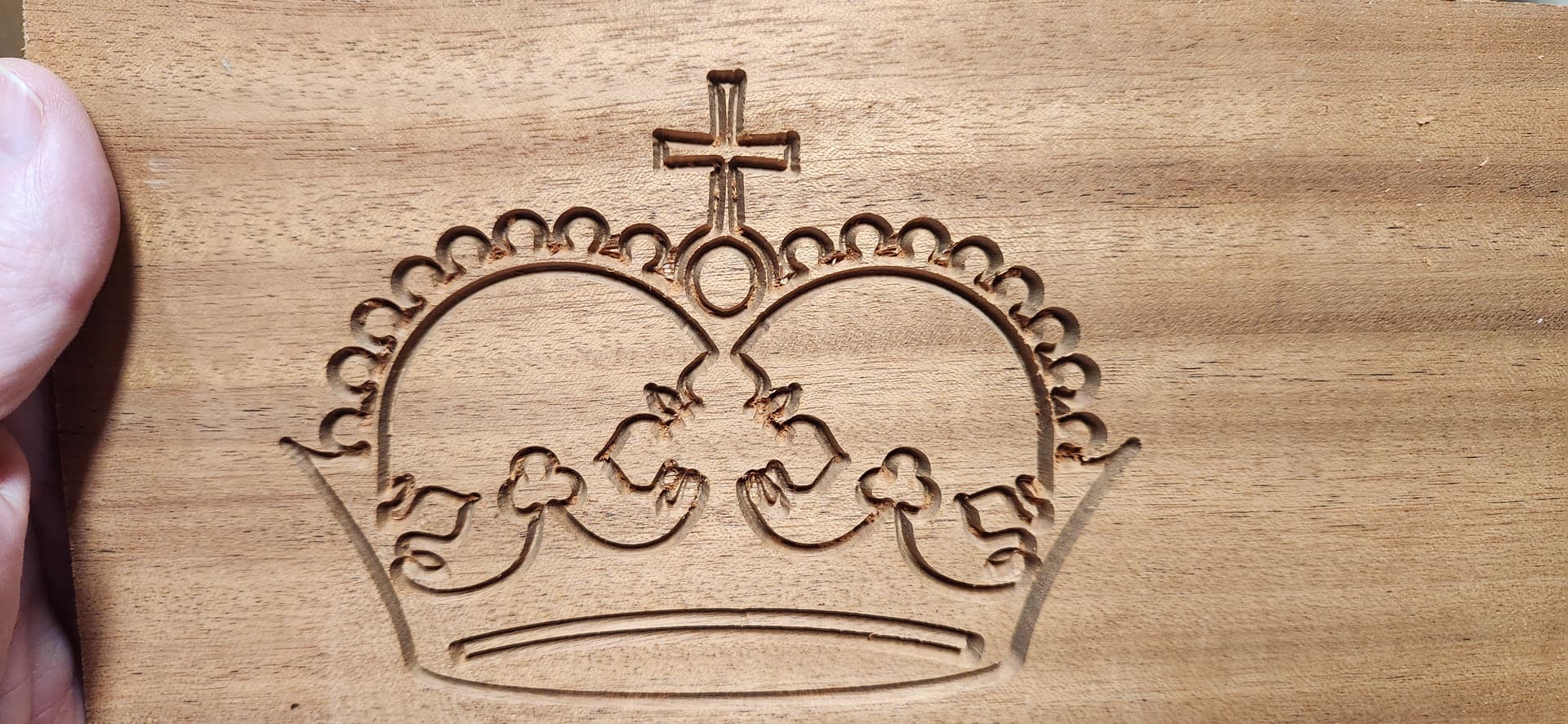
I bought this router for the LR3 over 2 years ago and tonight it still had the wire ties on the power cord. This is truly the first time it has ever made sawdust. I used a scrap of sapele (mahogany) about 1/4" thick and let 'er rip using a brand-new 30-degree V bit.
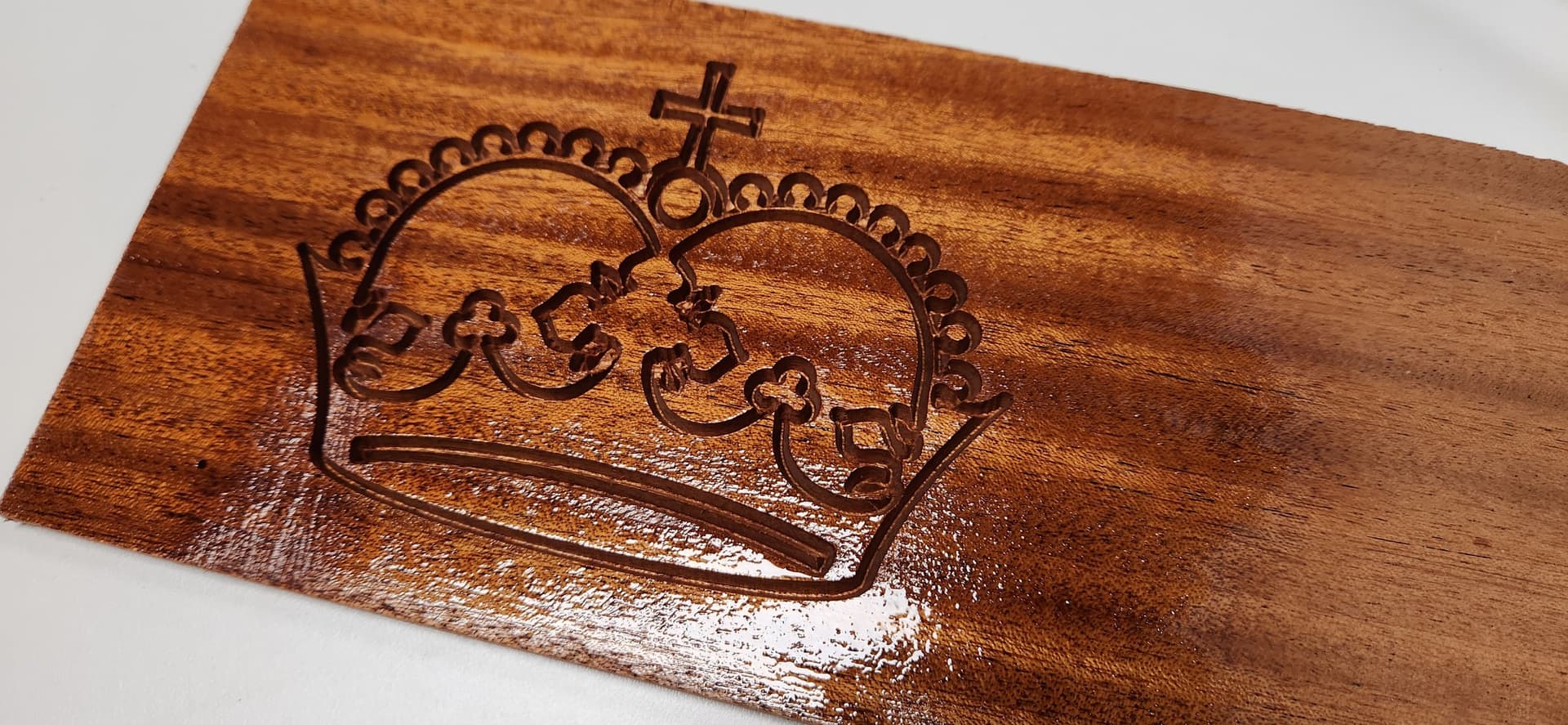
The cut came out great, but the sawdust was pretty tightly packed in. It took a good while to clean out the grooves, but this one’s a keeper. Last photo shows it with a couple of (wet) coats of spray lacquer.
9 Likes

3 Likes
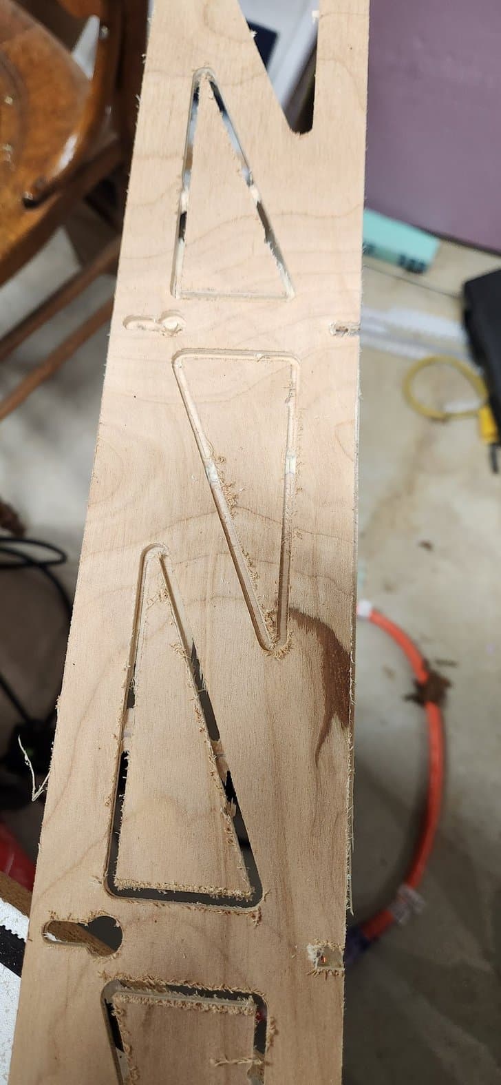
First through-cuts!
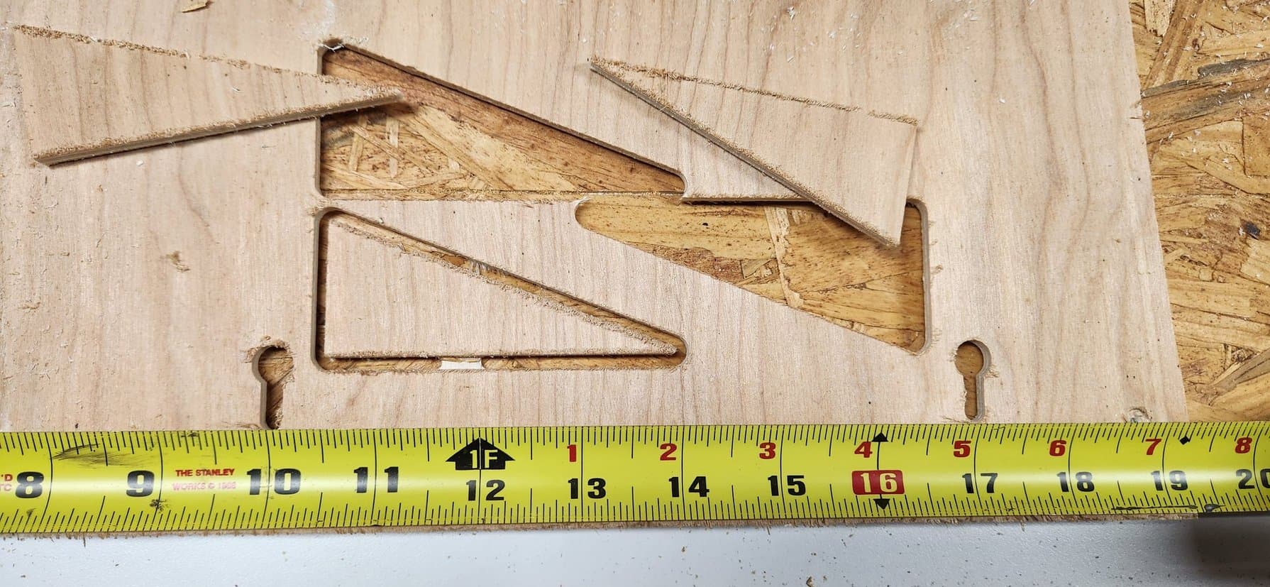
Weds night I began testing through-cuts for my gantry braces. Rather than try cutting the entire thing at once, I selected only two screw holes and two triangular cutouts for my first toolpath.
Several lessons learned (and to be learned) – my test cuts are in thinner plywood than the 1/4" stock I had set up in Fusion360 CAM, so on the first attempt, it cut right through my tabs. Not wanting it to grab the loose cutout, I hit the pause button in Fluidd, but the pause macro apparently disables the stepper motors! This caused the gantry to drop, plunging the spinning 1/8" bit into the workpiece, spoilboard, and maybe the melamine below that… TBD.

I then raised my starting point by 2mm and tried again. This time it left material on ONE of the four tabs, but it did much better overall.

I’m not sure what Fusion setting is causing it to lift out of the workpiece between passes. Any thoughts?
I should have gantry struts/braces by end of the weekend.
1 Like
Unfortunately fusion CAM is pretty hard to help someone with. You know how many tabs of settings there are so finding the right setting is tough. I can not recommend estlcam enough, everything you learn with estlcam will easily carry over to any other program.
3 Likes
Yeah, there’s a ton of options in Fusion.
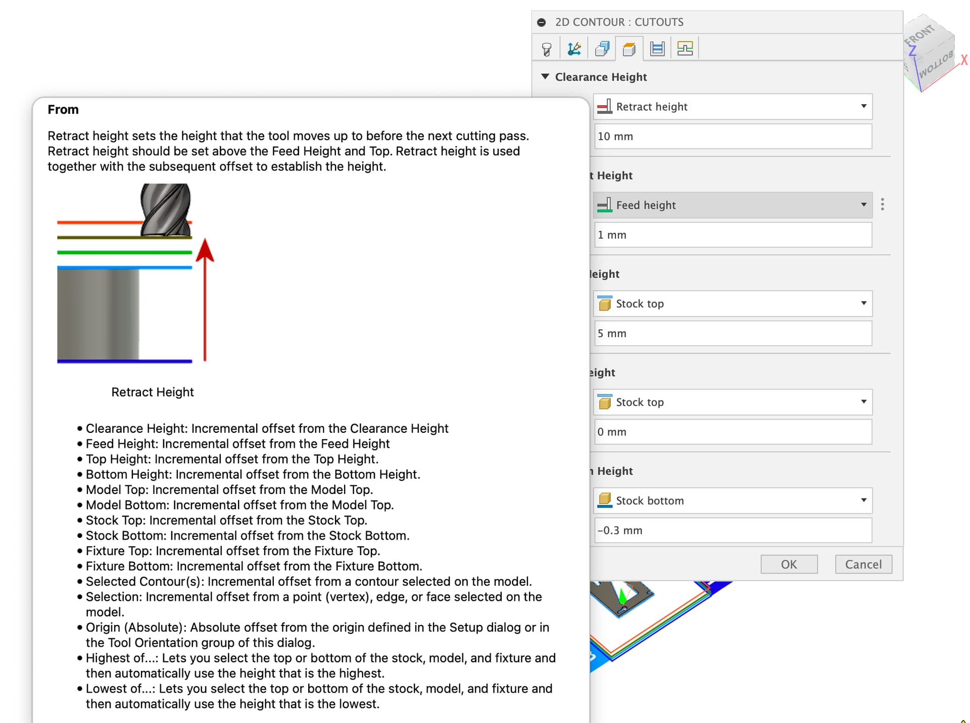
Fortunately, I was able to figure this one out. I learned that if you hover over any option, it brings up a nice “tooltip” style popup window describing the purpose of that option. This config turned out to be “retract height” in the Heights tab. Here’s the tooltip. Once I saw “before the next cutting pass” it was pretty obvious this was the right one, and I then set it to “feed height” which I think is the height of either the previous pass or the new pass.
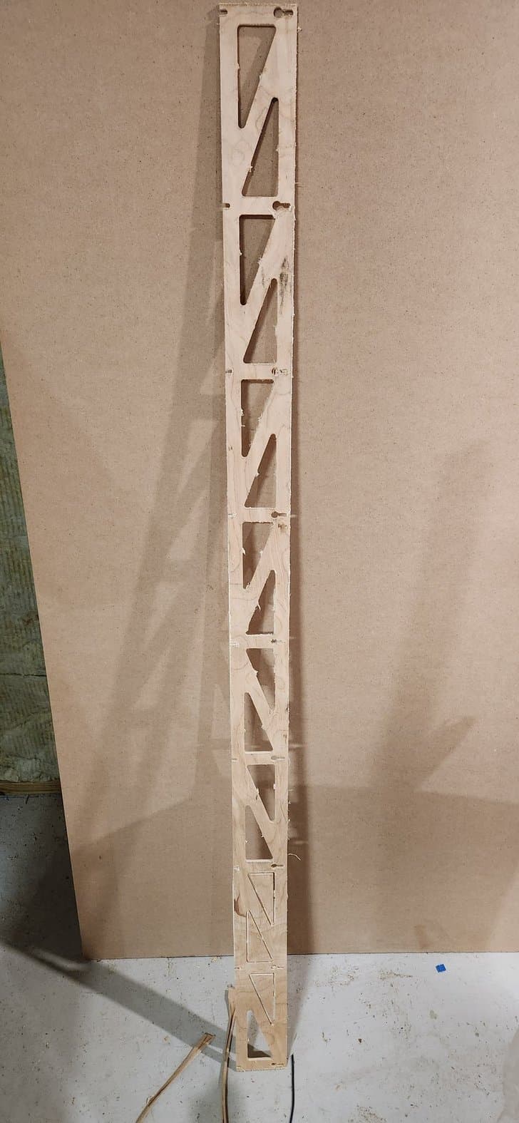
First strut/brace cut!
Using the ESTLCam postprocessor built into Fusion360, there are just a few things I have to do to get Klipper to use it:
- Rename the .nc file as .gcode
- Put a
;in front of all comment lines – by default these begin with( - Add a G92 near the top of the file to reset my origin
Other than that, it all works pretty well unmodified.
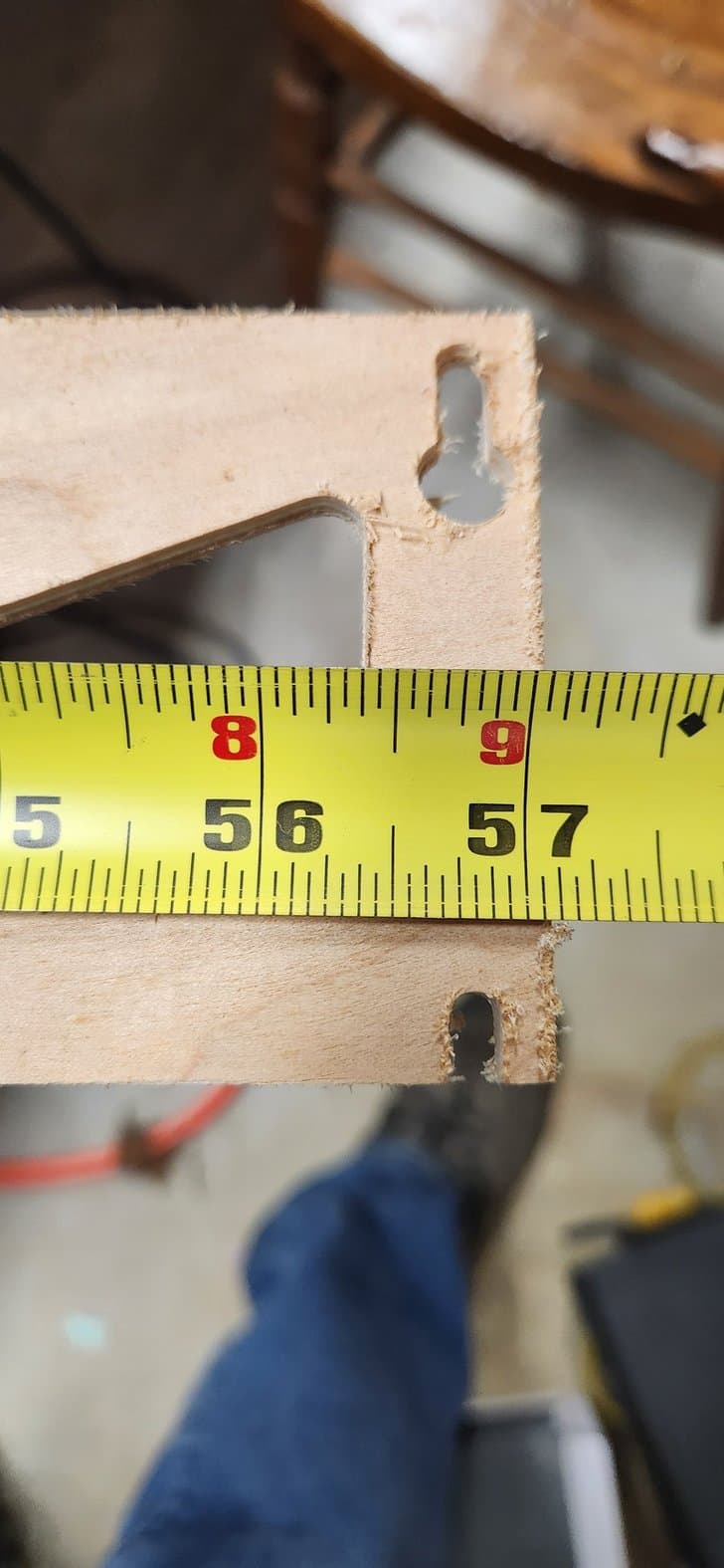
I first ran a movement test with the router turned off and the bit raised an extra 10-20mm just to check the limits of motion, etc. Then I cut the first strut, designed at 57". In the end, it turned out about 57 + 1/16" , but I think I can just edit my Klipper config file and fix that. The stock or spoilboard must have had a little warp in it (a low area) because a few spots didn’t quite get cut through. Just a little extra finish work will take care of that.
Happy to be making real cuts though!
2 Likes