hello everyone i dont know if this has been asked before but:
im in the process of finishing my build: a lowrider capable of working with a full sheet (4’x8’)
wired up everyting to begin testing and the Y1 and Y2 moves at different rates/speed/steps?
im using the SKR pro 1.2 board with the 2209 drivers and flashed the latest Dual end stops firmware.
*y1 is connected to the Y port in the board
*y2 is mirrored and conected to E1 in the board
I pulled my SKR Pro from my LR, but I seem to remember that the ports go:
X, Y1, Z1, Y2, Z2, so the Y2 connector should be to the E0, and Z2 should go to E1
For the Primo, the drivers are X1, Y1, Z, X2, Y2.
There are 2 ports for Z1, one should have jumpers on it. Leave that as is, those ports are in series.
Yes that way the skr board works, but i flashed the dual endstops firmware and the guide says that: E0 remains empty and y2 becomes e1 and z2 becomes e2. When connected like that y2 stepper becomes flimsy and doesn’t keep up with y1. Removed all connections and reinstalled again using e0 for y2 and e1 for z2 and works right away.
Already confirmed the flashing changes the .bin to .cur after initial boot with the sd card
With Extruders set to 1 The default firmware sets extruders to 0. I’ve checked the current version in the marlinbuilder releases (I was using it until a couple of days ago) and it has 0 extruders, so you leave E2 empty.
The X stop goes to X_MIN, Y1 goes to Y_MIN, Y2 goes to Y_MAX.
Z1 goes to Z_MAX, and Z2 goes to X_MAX. The touch plate goes to Z_MIN.
For the X, Y1, Y2, Z1 and Z2 stops (Z stops are at the top of travel) those should be normally closed switches (The little microswitches, use the 2 outside pins, not the middle one) and make sure you connect them from signal to ground on the motherboard. Don’t use the +5V pin.
The touch plate (If used) goes from signal to ground, and is defined as normally open.
another quick question: is there any wifi module compatible with the SKR pro 1.2 (from the shop) i would really like to add this, so i dont have to hardwire any pc or raspberry pi to the machine
I have some of the ESP01S modules, based on an ESP8266. It adds wifi, and there’s a port on the SKR Pro 1.2, as well as one on the TFT35 E3. If it’s on the motherboard, it can only access the SD card on the motherboard, but when added to the TFT35 E3, it can access the SD card there, or the USB port.
If you add it to the motherboard, you need to recompile the firmware with the wifi serial port activated. With the TFT, you only need to update the config file (Put it on an SD card and turn it on)
This has some downsides. It only works in TFT mode, not in Marlin mode. There still seems to be some funny business around filename limitations on the SD card with the firmware that I found. Last but not least, you’ll need an FTDI interface to flash the ESP01S module. I did OK with a USB to serial adapter that I had onhand, though. Still, the ability to transfer files to the machine over wifi is great when the machine is on a different floor than the computer you use to do your CAD/CAM.
yes, the idea is to keep my main computer out of the room because i dont want to clean my pc daily for all the dust. but if its a pain in the ( * ) im going to keep a raspberry pi hardwired to the board instead and place a wifi repeater in range and call it a day!
A Raspberry Pi with Octoprint or the V1Pi project is definitely easier. I used Pi3A for a long time and was reasonably happy with it, except then I needed a wifi device (My phone) to start the jobs I uploaded to it.
Eventually, I went to the even more expensive solution of changing over my hardware to Duet with RepRapFirmware which can be controlled locally through the panel to cut jobs uploaded over wifi.
Resoldered the limit switches, and replaced the placement for the z limit switches, pre-printed those parts now printing the new y limit switches holder for the y axis because im using the old stile yplates with 4 wheels (old but allows a more firm axis imo)
The machine worked fine while using a small area (short distance of the Y axis)
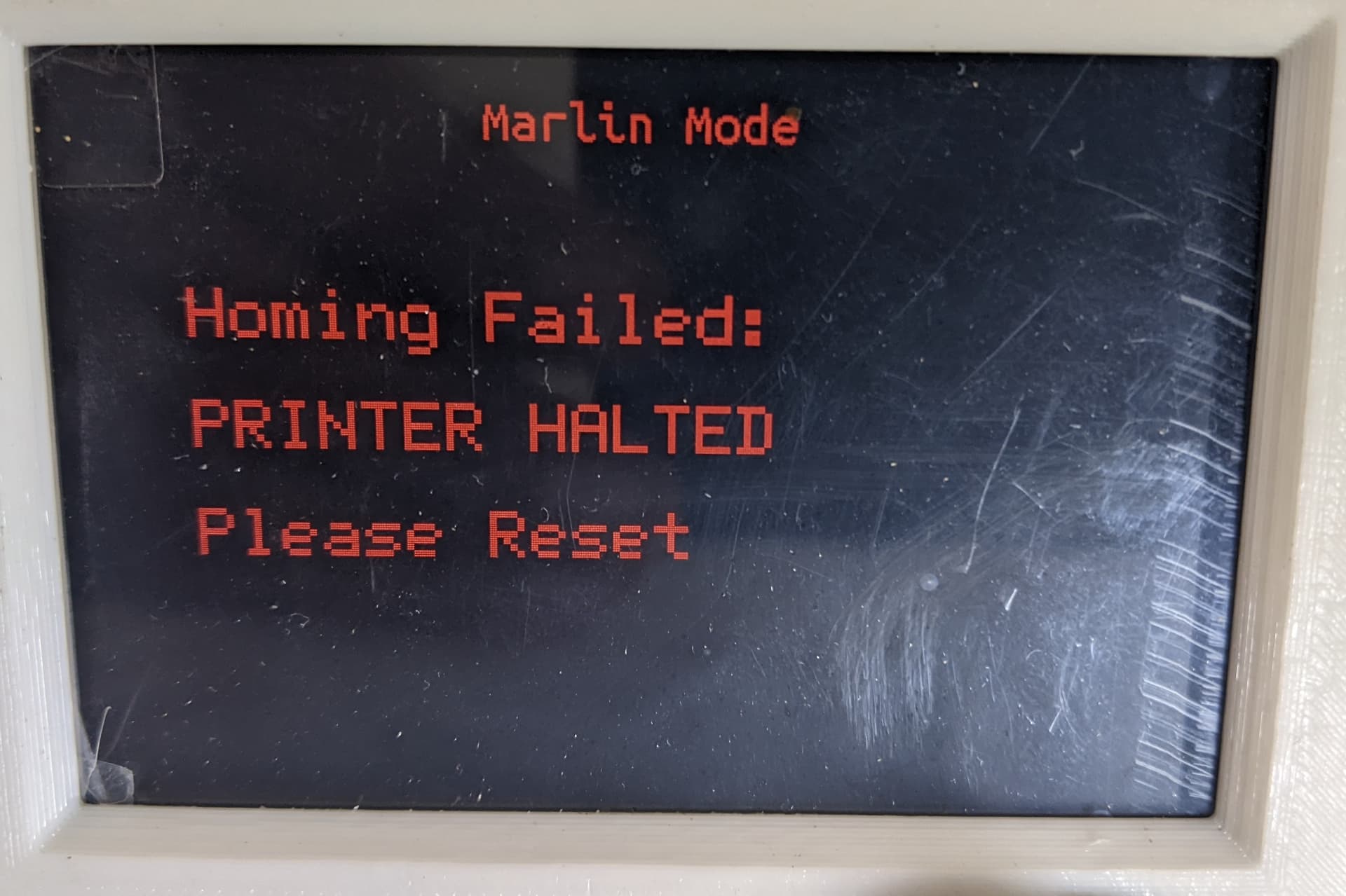
but when i moved the machine to the max and try to home the y axis it only moves 90 cm and then the tft screen displays an error:
90cm might be the new value for 513. Unfortunately, that isn’t something you can change easily. You have to change the bed size and recompile the firmware. We can’t put it at 10m or something, because then it would try for 10m if something was wrong with the switches.
That is totally normal though. Nothing unexpected. You can either recompile the firmware, or put an X on your spoil board at 900,900 and just jog the machine inside the X before homing.
 now i know where is my problem. will resolder tomorow
 test i think the machine is perfect… Have to sit and make and 3d print a pencil holder
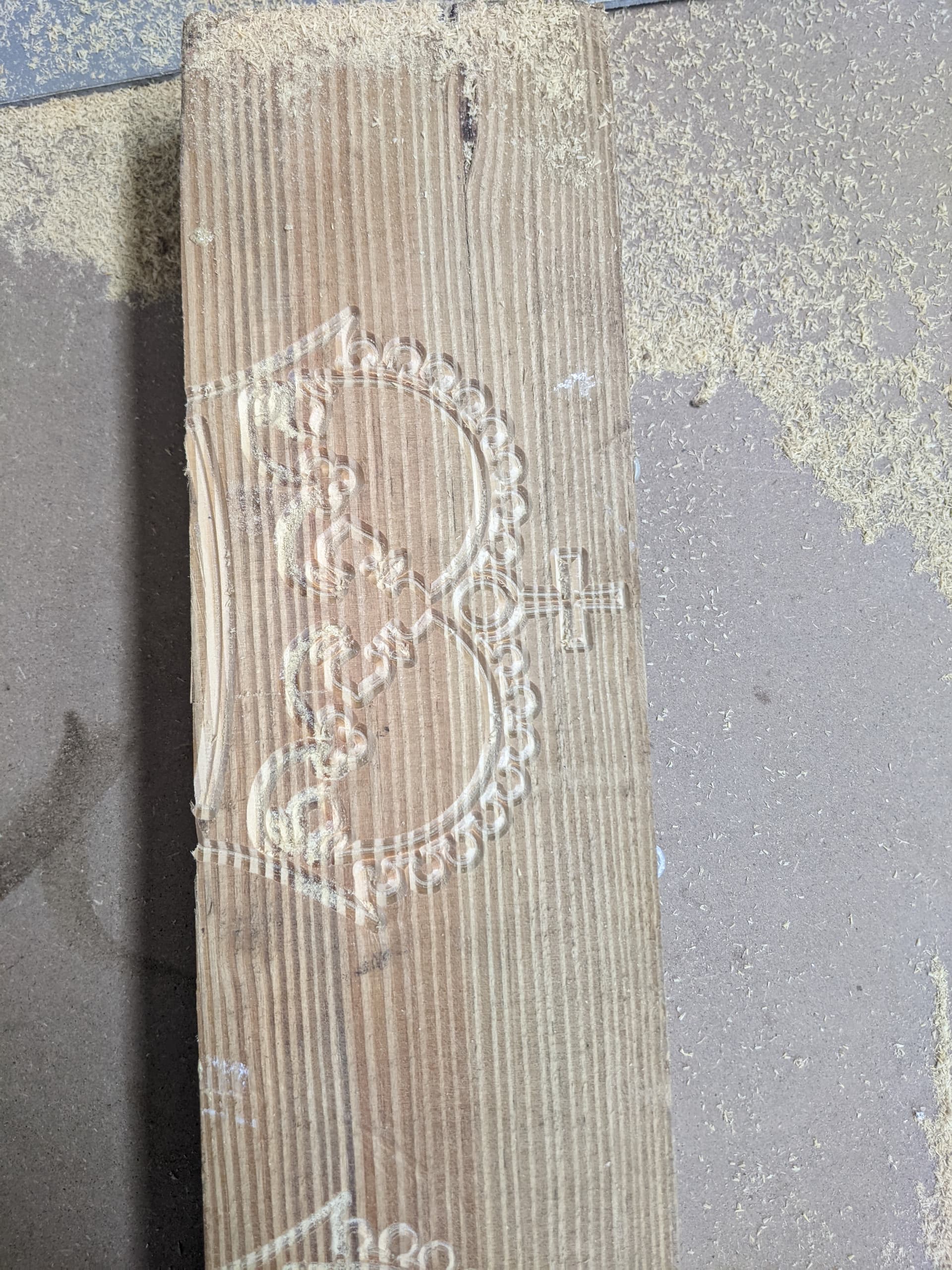
 cant wait to begin experimenting with pdvf anf soft woods