It just moves them a tiny bit, more of an angle that slots. I know it seems wierd but it also seems to happen far more on prints other than the ones bought from me so it has to be some sort of print issues that is very slight.
Mine were also full-threaded, does not change anything. ![]()
Thanks Philipp! Good to know that using fully threaded bolts can be taken out of the equation…
I’m away working at the moment so can’t try as Ryan suggests and apply tension to the clamp using the tension bolt first. (I had previously attempted that but it didn’t seem to have much of an effect which is why I was considering what else might be causing the problem.) I’ll have to try it again when I’m back home.
1 Like
Update: 25 July 2023.
I had another go of applying tension to the clamp bolt (while the other two attaching bolts are loose) to set the mount bolts correctly and close the gap between the tubes and the bearings. It did lessen the gap but I was putting on more tension to the clamp than I was comfortable with. (The clamp was squeezing the bearing to the point where it amost was jamming it.)
I’m still not happy with the gap between the thread of the bolt and the bearings inner race as this introduces a lot of play, and I also suspect my cheap bearings from Aliexpress may also add unnecessary play. Might have to source some better quality bearings and different bolts
As my tubes are 25.4mm, I’m using the “J” version 3D printed parts…so I decided to re-print the core clamps but this time print the “F” version which are for 25mm tubes, to see if the .4mm difference would help close the gap.
I’m happy to say it does. With just a small amount of tension on the tension bolts (and sometimes none at all) the gap completely closes up between bearing and tube…or does it???
I found that if i rotated the tube, in one positiion there is a small gap and hence some play, and in another it is too tight and the bearings seem to be under load. That must mean my tubes aren’t perfectly round! Grrrr
I don’t know why this isn’t noticable for the trucks on the side rails as all the tubing was cut from the same 6m length of stainless tube, maybe it has something to do with the position of the bearings on the trucks and how they connect with the rails.
Anyway, I’m hoping when I assemble it now, I can rotate the core tubes to a position where the fit is nice and snug with zero play and then lock them to the trucks so they don’t turn.
Progress I guess!
1 Like
Hi Mark_Kiwi , if you are ever in Whanganui you are welcome to call in. I have completed Primo and LR3. I also have a ZenXY underway.
Paul
2 Likes
Thanks Paul,
I do occasionally get down that way with work…more New Plymouth or Palmy but in the general area ![]() so I’ll keep it in mind. Thanks!
so I’ll keep it in mind. Thanks!
Mark_Kiwi, where are you based? I am in the Waikato and thinking of embarking on the same journey as you.
Hey Don,
I’m in West Harbour in Auckland but did source my SS tube in Hamilton.
Started assembling but suspect my cheap Chinese bearings are no good because I was having issues trying to square everthing…so have put everything on hold until I source some more.
Also had to put everything on hold because my wife has had hip replacement surgery.
Currently my machine is under a sheet in the garage waiting for me to get back to it…best I pull finger and souce those bearings.
I’m thinking I might disassemble everything and start the assembly from scratch. Maybe my rails aren’t perfectly square, I need to get that perfect and try assembling it again.
Good luck!
Mark
1 Like
Well it’s been a while since I’ve done any real work on my Primo…(My ender 3 got some upgrades so I’ve been 3D printing more than working on this)… and I’d had a lot of issues trying to square everything up when I was assembling it so I put it aside for a while as I contemplated what to do next. (Then I had a few life things get in the way, so it’s been sitting in the garage under a cover ever since.)
Recently I pulled out the tinyBee, loaded it up with FluidNC and got it to the point where I could move some steppers. (With the help of a crimp tool and connectors from aliexpress I have changed the connectors on the stepper motor cables to JST so they now plug straight into the board.)
I have also decided to bite the bullet and use the 20mm dia linear rail I had on hand for the core rails, in the hope this will be stronger and nice and square…the challenge was how to do this without a complete redesign/reprint, and still be able to revert back to the stock standard design should my hairbrained ideas fail to work.
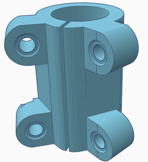
What I came up with was this…
2 Likes
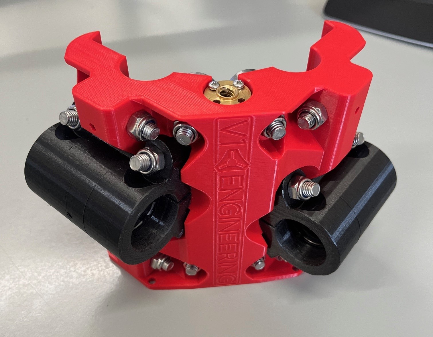
After printing and removing support etc, the linear bearing is pushed in and secured with circlips. (The unit is split to help with the installation of the bearings, but when bolted to the core is very secure.)
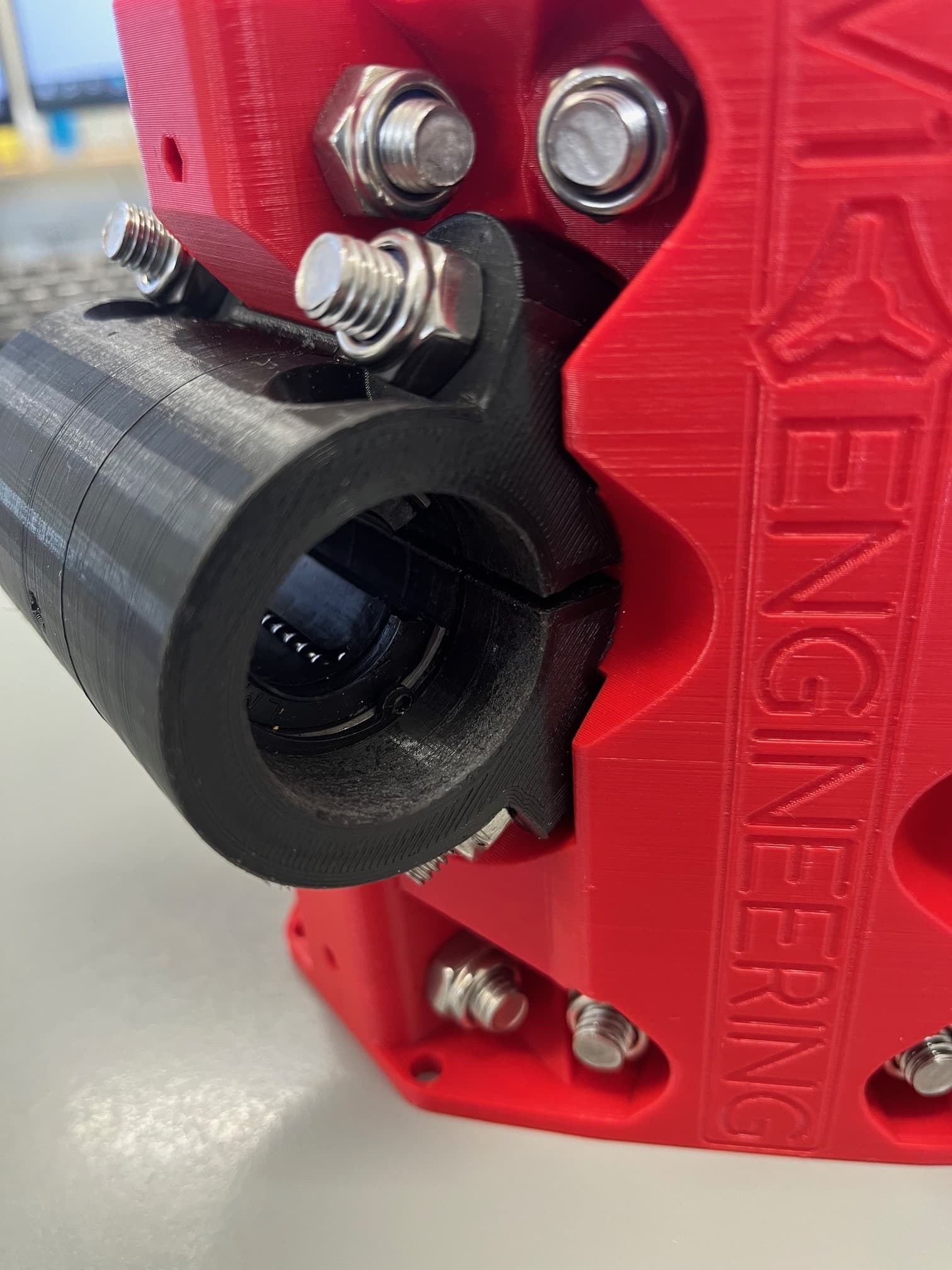
Where the 20mm rail attaches to the trucks, I made a simple adapter to convert 20mm to 25.4.

I was concerned that I may have trouble squaring the trucks and was thinking about trying to design some sort of bracket to make this area stronger and square, but then realised that with the tinyBee having XXYYZ connections and FluidNC, I should be able to do auto squaring of the bed. Also with the (hopefully) improved rigidity and squaring at the core, it should theoretically be quite square.
I’ll now look into making some endstops with fine adjustments to help with setup/squaring…something like this…
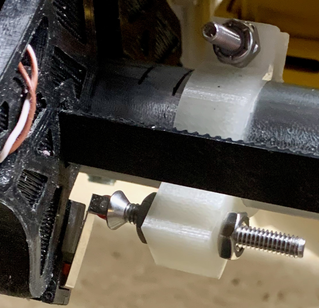
(MPCNC Primo adjustable end stop by dav3103 - Thingiverse)
2 Likes
All boards that have shipped from V1 include the ability to autosquare. Whatever you had previous to the tiny bee should have been good to go if you got it from us.
Success! My Primo is moving and first Crown picture has been drawn!
A quick summary of the machine…
Workable area is 450mm x 540mm
Uses a MKS TinyBee controller
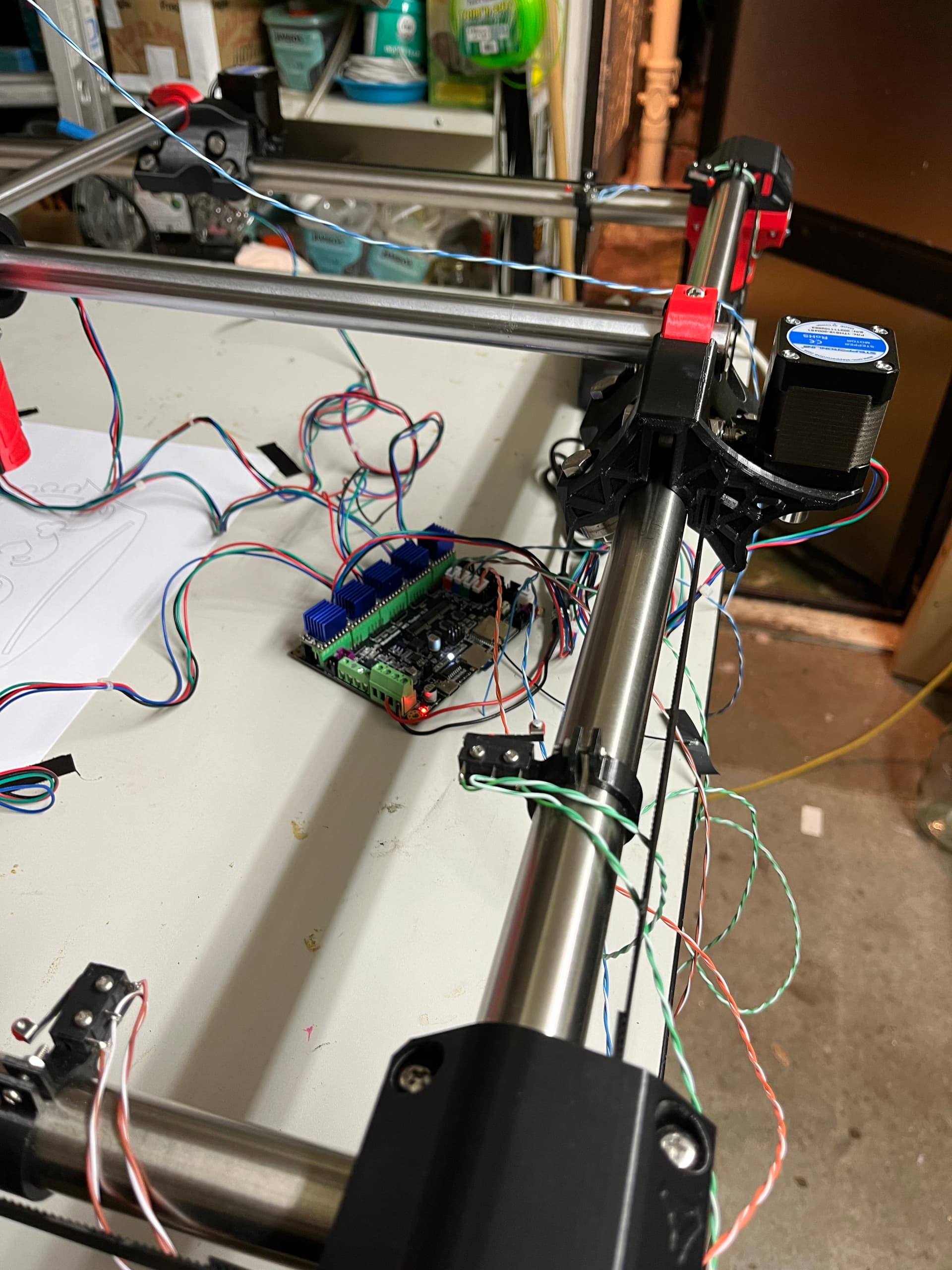
Each x and y rail has a neg and pos limit switch (NC connected in series, active high) so auto-squares. The Z axis pos switch is actually screwed to the nut retainer support inside the bottom of the z-axis rail. The microswitches have little rollers on the end and this protrudes out the bottom of the z axis tube so that when the z-axis is fully retracted the microswitch activates. (so have a total of 9 switches in all)
Didn’t end up using the adjustable limit switch as seen in an erlier post, instead I used the following that I modified for 25.4 tube. MPCNC Endstop Mount (for 25 mm tube) by gercole - Thingiverse.
I checked the squareness of the machine by motoring to the extremes and driving the unit both x and y so the pen marked the corner points. Then I checked the diagonal lengths between these and adjusted the endstops until the drawn corners were equal.
The adapters I had made to use the 20mm linear rail as the core rails, were crushing the linear rail bearing when I tightened their securing bolts on the core, making the bearing bind a little. So I 3d printed some 0.6mm thick spacers and that seems to have improved things.
Heres my crown
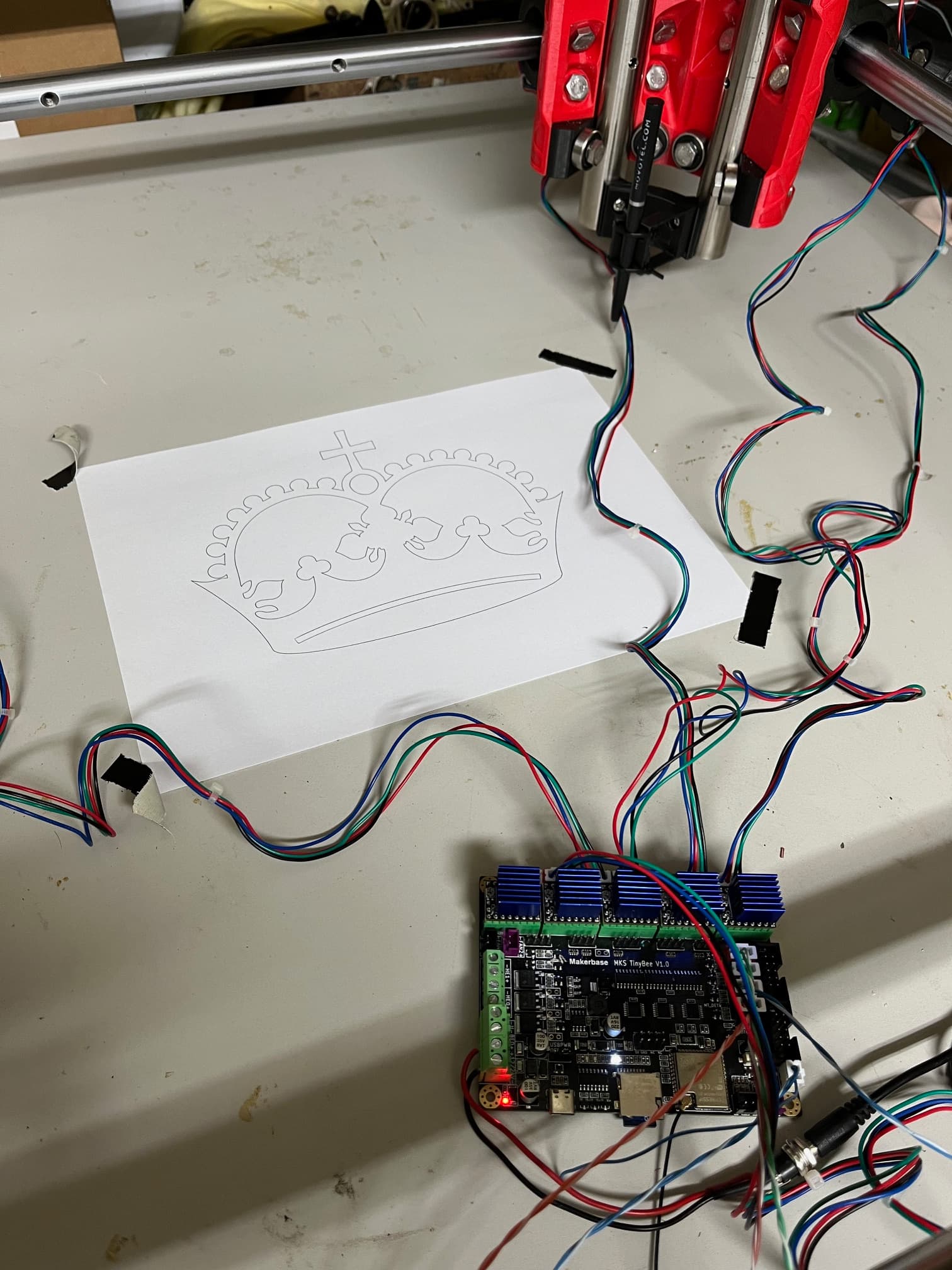
You can see some of the limit switches in this photo
Now I need to make some cable chains and a box for the control board, figure out how to use cad/cam software, fit the router and make some dust!
2 Likes
Looking good, have fun with it.
You know you can screw the switches to the trucks? Then you can bundle the cables with the motor cables. ![]()
Yeah, I would think the switches being mpunted lime that would be a snag hazard. There are provisions on the trucks to mount the switches there.
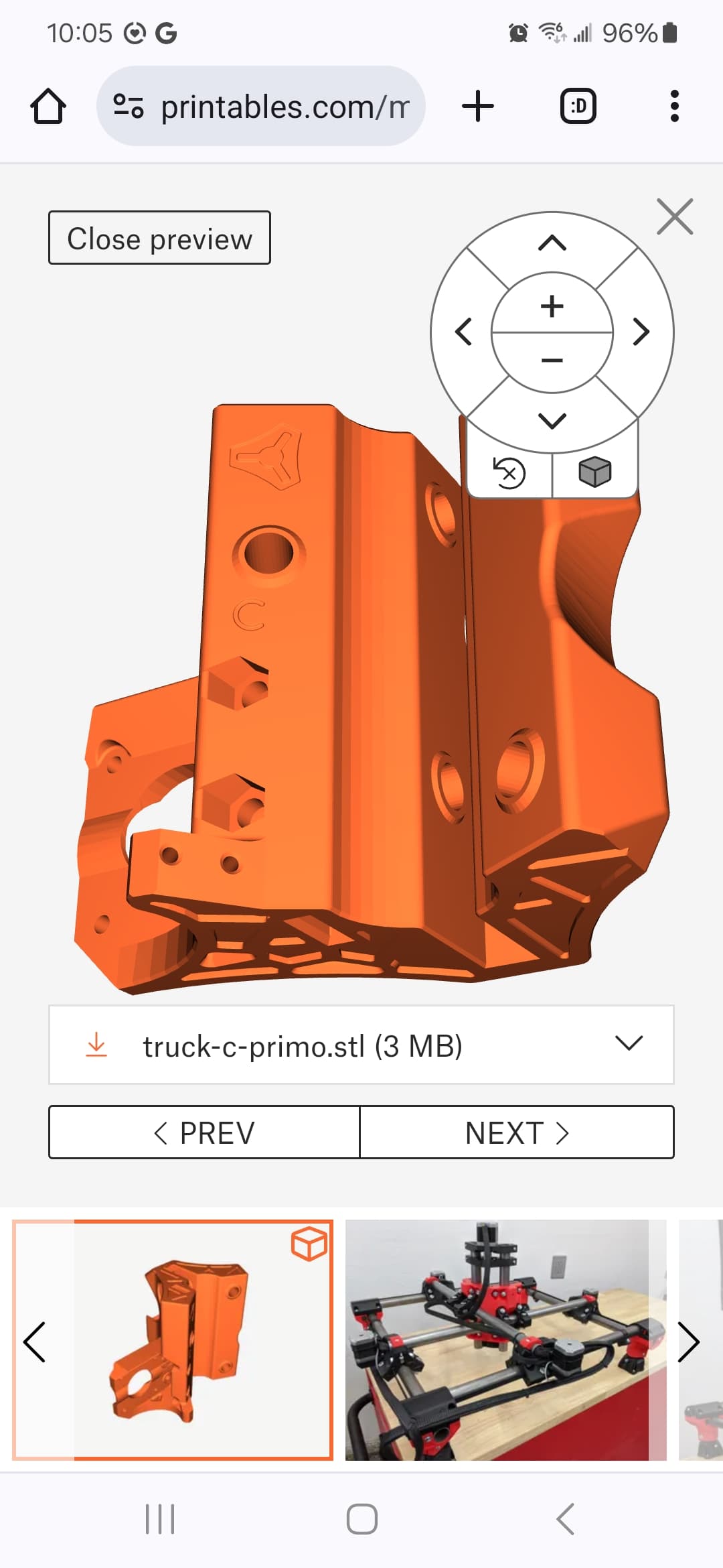
See the 2 little holes at the bottom? Those are to hold the seitch so that it only needs a block to tap against. It’s less in the way and fewer wire runs.
The wires to the switches may need to be longer though.
1 Like
Yeah I might look at doing that. The truck has one mount, but mounting a switch for the positive end hard stop might be a little trickier.
1 Like
Yes I originally had a switch mounted there, but then decided to mount a switch at either end of each rail so there was a hard limit at both ends. I may go back to just a single switch and have a soft limit if it gets too annoying or difficult to tidy the cabling.
What’s the goal behind having a switch at both ends? The steppers aren’t strong enough to need mechanical protection from overtravel. If it happens then the truck collides and the stepper skips steps without damage.
I don’t think the homing switches are respected as limit switches in the firmware by default anyway.
It also adds a potential failure mode where if you start homing while at the furthest point from the home position and with one switch tripped, it’ll drive one truck further into that switch trying to back off and drive the other truck in the opposite direction.
I have mine configured with the switches on each truck and that’s what I’d strongly recommend others to do.
I was just being over cautious…Basically after spending so much time making this amazing machine, I didn’t want to break it if I did something stupid (very likely if you ask the opinion of my wife or kids ![]() ) like try and drive it off into the neighboring room…but you are correct it shouldn’t be a major.
) like try and drive it off into the neighboring room…but you are correct it shouldn’t be a major.
I’m running FluidNC on a MKS Tinybee controller board with the negative and positive switches in series. This means if one of the endstop switches is tripped, it doesn’t know which end it’s at so the software won’t allow you to move it or run a home until the error has been cleared. The process is to power down, move the unit off the limit switches, power up and run a home.
You have convinced me…and now that I know the extreme range of my machine, I think I’ll drop the postive endstop switch idea and go back to just a single switch mounted on the truck and set the maximum travel as a soft limit in the yaml file. Assuming I home every time, I should theoretically never run into any of the ends…theoretically!
![]()
1 Like
Understandable, for sure. You won’t. I’ve crashed my trucks tens, maybe hundreds of times. The homing switches won’t stop that, anyway. That’s kinda the good and bad side of these things as a design, there isn’t enough power to get in real trouble but there also isn’t enough power for them to be a true workhorse. Great if you’re a hobbyist and want something to play with that’s super capable. Not so great if you’re trying to find a cheap way to build out a production line.
Right, I’m using Marlin on a SKR Pro and had forgotten that most people will be heading down the FluidNC path now. No drama there, then.
Don’t worry about it. In fact, I’d go so far as to say do it deliberately, get it out of your system, see that nothing bad happens and then breathe easy ![]()
2 Likes
Marlin will also only obey the awitches during a homing move, and happily ignore them rhe rest of the time.
V1 maintained firmware also does not require homing at all, and will allow you to move your axes to negative (which you so want.)
Fortunately, as stated, the whole thing is optional, and if you’re careful, you should never hit your axis limits.