New Build in Vancouver Canada

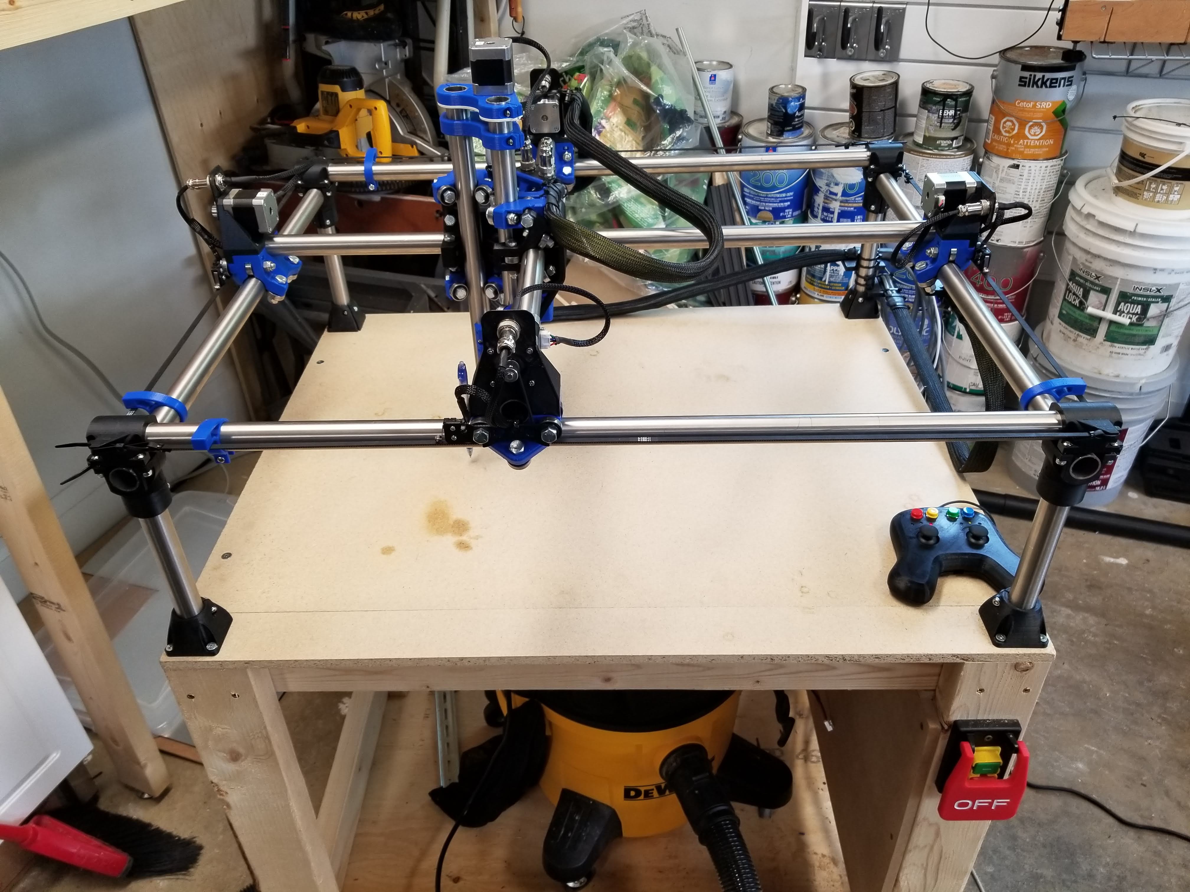
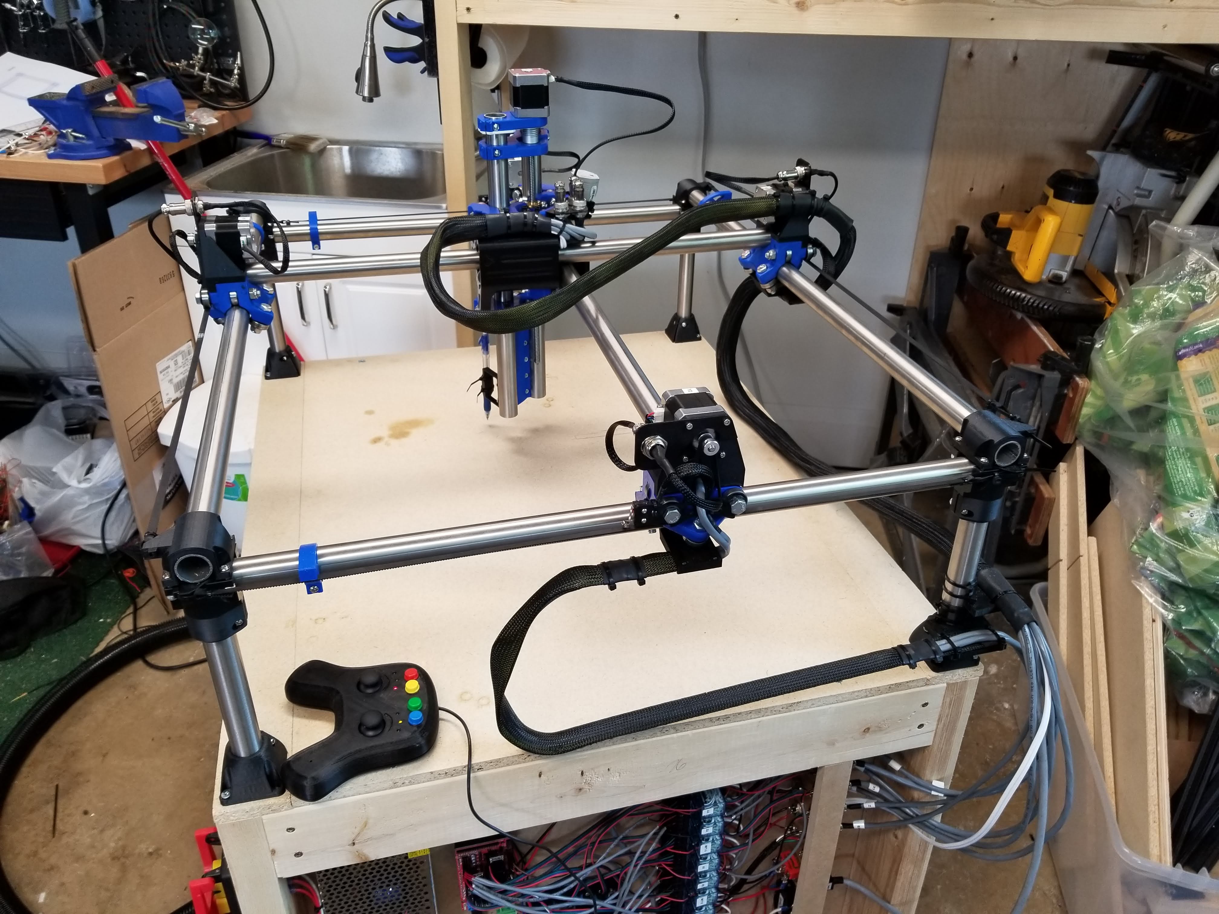
Hello all! I started this project almost exactly 2 years ago, and after lurking in the forums for a couple of years and slowly making progress on my MPCNC, I’ve finally got it moving! I have decided to call my machine “Jack”, because I always intended it to be a Jack-of-all-trades (master of none). My goal was to do milling, laser etching/cutting, drag-knife cutting and also large 3D prints. So against all recommendations, I made a fairly big 24" x 18" x 8" usable area machine with 1" stainless tubing and dual endstops. My router is a Bosch Colt GKF125CE that I got on sale awhile ago, with a 1/8" collet from elairecorp.

I stumbled upon a failed 3D printer project on craigslist that provided me with the steppers, RAMPS, leadscrew and a bunch of other bits and pieces for super cheap, so that got me on the way. The rest of the hardware was mostly from Aliexpress, Homedepot and a local electronics store.

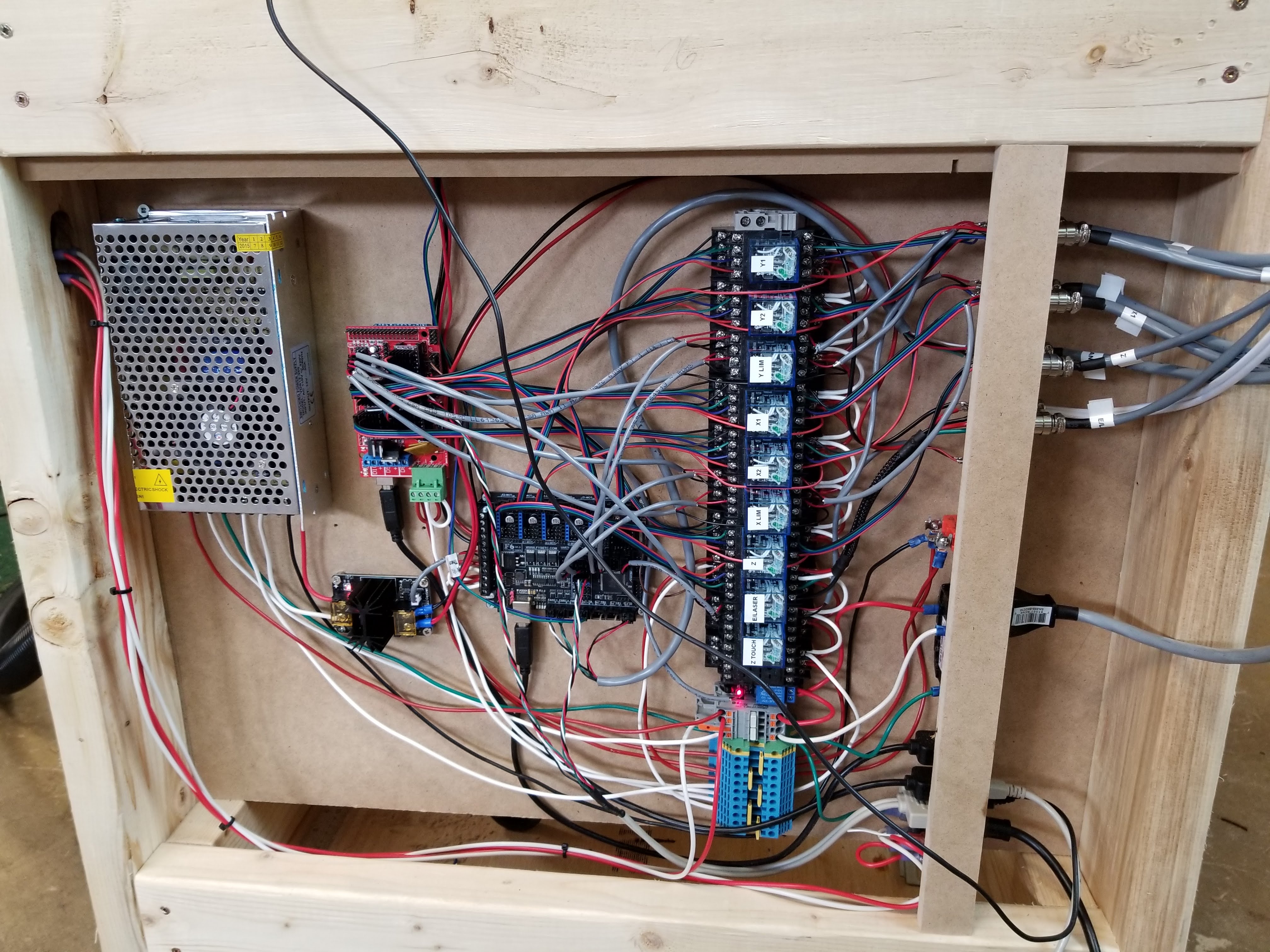
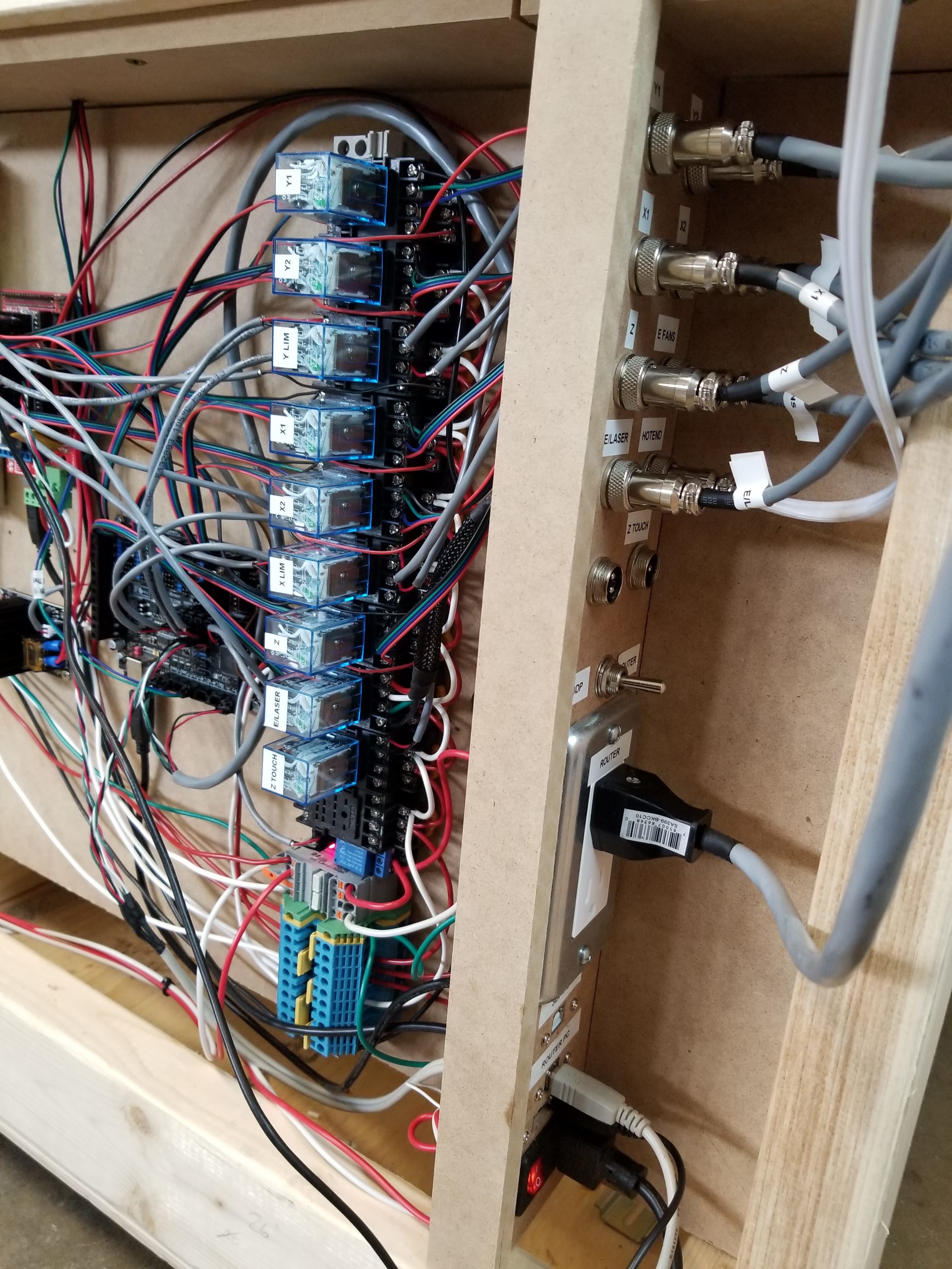
With wanting to be able to do all sorts of things with this machine, I decided it might be easier to have 2 sets of firmware; one for CNC/laser, one for 3D printing. To do this, I used 2 control boards; RAMPS for CNC, Fysetc F6 (6 driver board) for 3D printing. To easily swap between the two boards, I put in a bunch of mechanical relays to swap steppers and switches etc. between the two. Thus far, that hasn’t seemed to hurt anything (other than the time it took to wire the whole works), but I haven’t tried the F6 board yet.

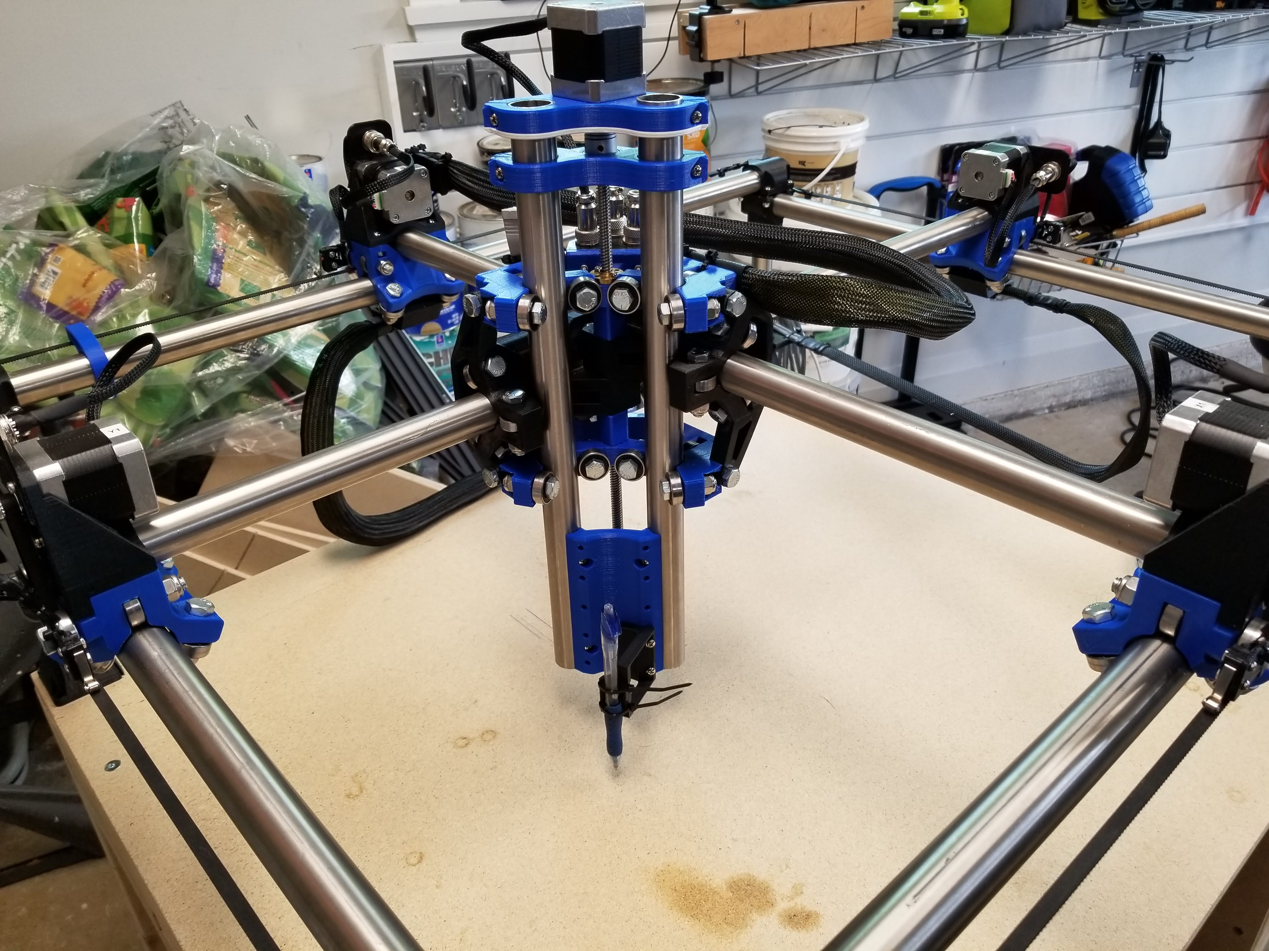
Having taken so long to build, I went through the 525 prints, then did the Burly prints, and if it weren’t for the pandemic, I might have also had the Primo prints done before finishing! One hiccup that I came across though is that my tubes that were advertised as 1.000" OD, were actually 25.8mm (1.016"). Everything fit together, but it was pretty tight and “crunchy”. I decided to reprint a few parts, egging the bearing holes about 0.2mm outwards in Tinkercad, and it made a big difference!

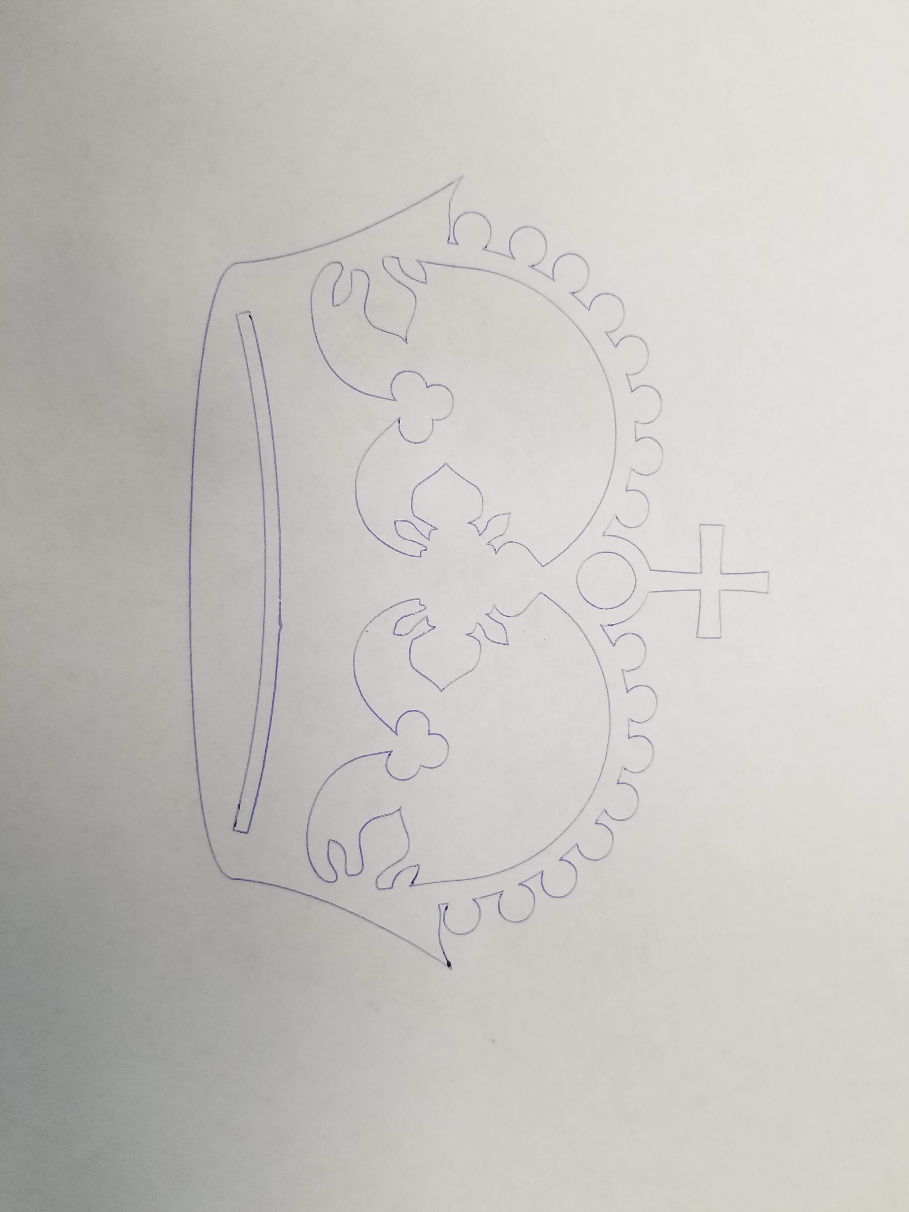
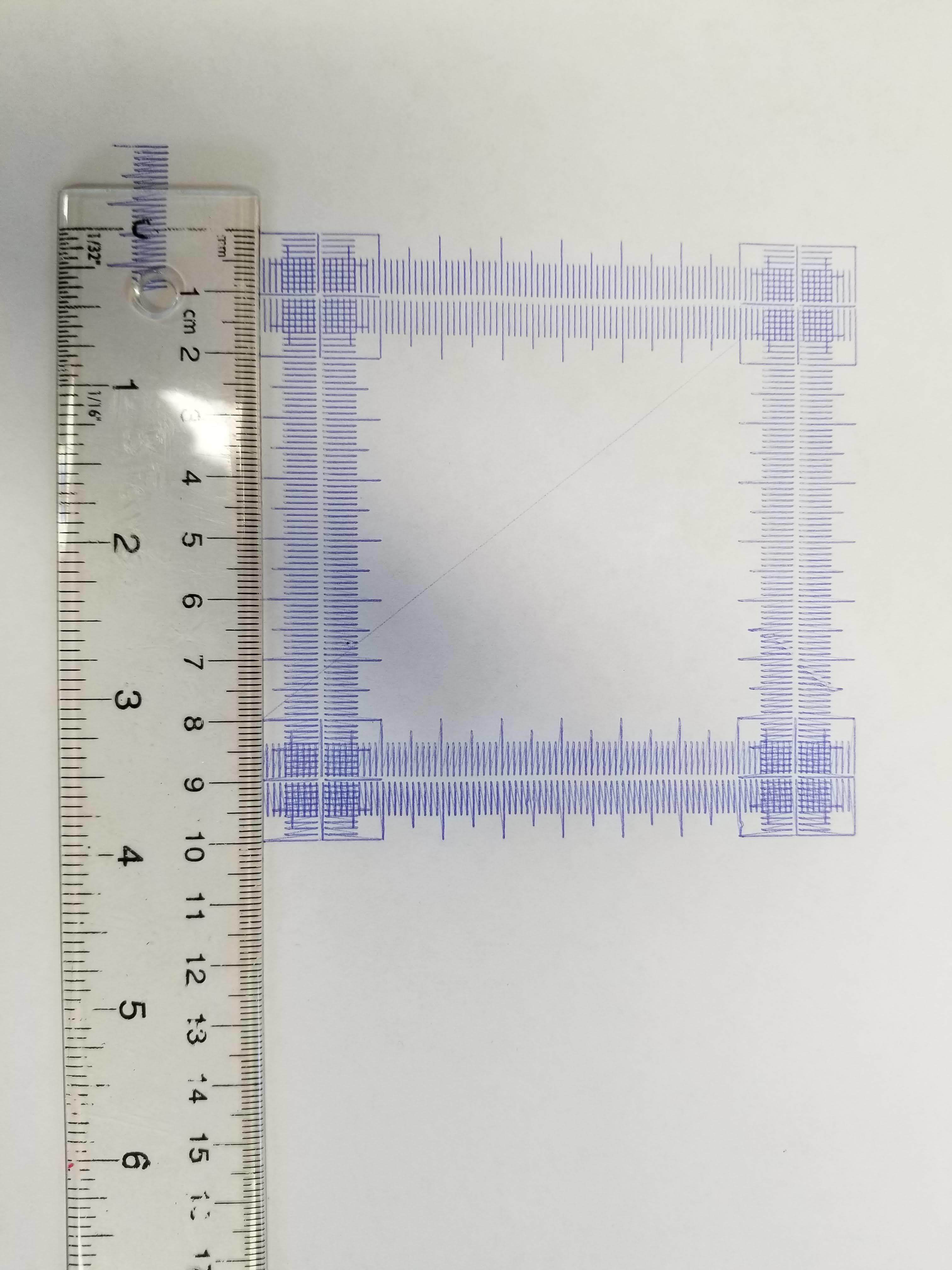
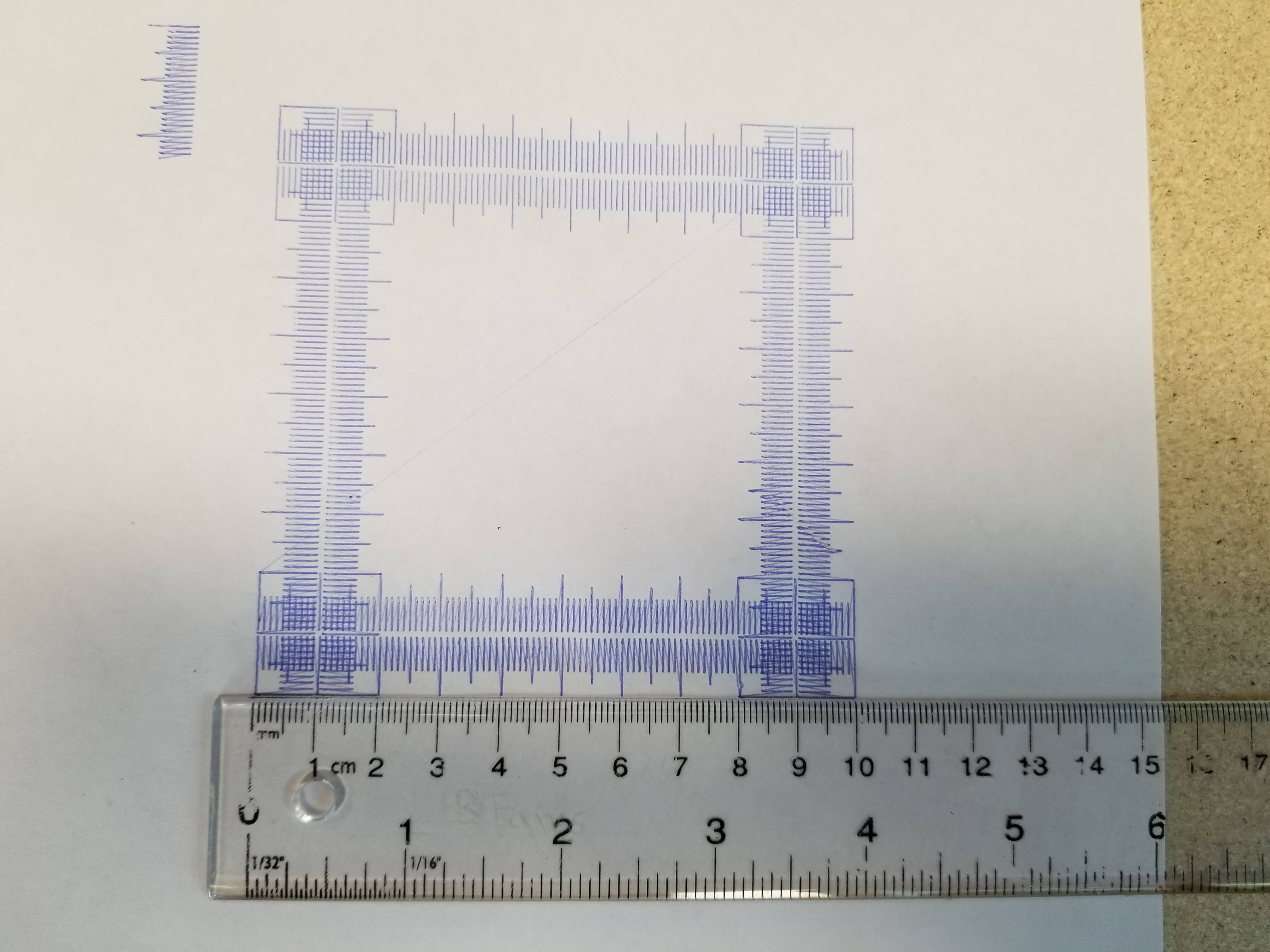
Crown test came out great, and the rulers were dang good too. A little backlash as a couple of belts were looser than others. Also it appears my spoilboard isn’t exactly level. I guess the best way to deal with that is to get a surfacing bit and face the whole board? @forcerouge controller is pretty sweet jogging things around.

I just so happened to lend my router to a friend last week, so I can’t get things dirty yet, but soon!

7 Likes

Wow. That is a lot of relays. Looks big too. That crown and cal test look great. The stainless really makes it pop. Thanks for sharing.

1 Like

Yeah, they’re 4-pole relays, so 1 per stepper, 2 for the endstops, then 2 for accessories. Could probably make do without switching the Z-min, but I haven’t decided if I want that for 3D printing or not yet. Also have a small relay for turning the router on and off.

It isn’t a small build, but no flex that I can see pressing things by hand. Once I get the router cutting into something I’ll get a better sense of the rigidity, but so far with the steppers energized the only hint of movement by hand is the belts stretching.

2 Likes

That thing has to sound awesome while running!

1 Like

Very nice build!

I thought about doing this kind of dual board setup, but gave up because it sounded like a lot of trouble. My Idea was a bit different though, I was thinking about making a single wiring harness plug which would fit both boards. This way I’d just have to unplug the first board and then plug onto the second board. Your idea is more elaborate, but even more complex, I’d be a bit afraid about long term reliability, troubleshooting might be difficult (but it’s a fun mod and it might work just fine, try and see!)

Super happy to see someone else using the remote controller too!
Keep up the good work, now time to make this machine dirty!

2 Likes

Thanks. Yeah, I debated doing something like that, just having different plugs for the different boards. But for me personally, the relays actually seemed like the simpler, more elegant solution. We shall see how it holds up though!


I’ve worked with worse cables…

I have a couple of 10pin XLR connectors in my build (along with a bunch of 2,4 & 6 pins), and soldering the 10 was not fun at all. Although those were 16mm, the one you linked being 55mm would probably be ok.

Absolutely gorgeous. I wish I could get my build this clean!

1 Like

Did some laser testing today. After reading through a few hundred posts on the topic, I think I grabbed the important bits. Did the Marlin edit, remapped pin 44 for the PWM. Using a 5.5W (advertised) laser from Aliexpress produced some good results with an air compressor assist. After running the focus scripts, got this burn on the second round of settings on corrugated cardboard with ImageToGcode 1.2.9.

Not too bad I think, should I try upping the power and going faster? 60mm/s burn, 200mm/s travel, 25% max power, 0.15 vertical/horizontal resolution. 50mmx50mm image size.

I’m also pretty happy with the air assist. Just a cheap Aliexpress mister body with real loc-line (the cheap stuff leaked so bad my poor little compressor couldn’t keep up. The real stuff was actually pretty cheap and doesn’t leak at all). Zip tied that to the gantry with a quick connect to the compressor hose. The hose drags a little, but the laser is so light it doesn’t seem to have any effect.

4 Likes

Do you have a link for the laser you got?

That’s the one I got. I have only just started playing with it, so I can’t vouch for longevity or if it’s actually 5.5W, but it sure can burn through stuff if you let it!

2 Likes

Well, my build has only been running for about a year and a half, but I’m starting the upgrade to Primo! I had the upgrade kit on my wishlist, and my wife bought one from Ryan for my birthday! Unfortunately she misunderstood how much belt I needed and only got 1m instead of 4m :frowning: But I can wait for an aliexpress delivery since I have other pieces I want to pick up.

While there is nothing wrong with my machine, and has done great for the carvings I’ve put through it, I now know better the features I want/need, as well as some bits I want to improve on.

For starters, I never got the 3D printing side going, as I found a ridiculously cheap 330mm x 330mm x 420mm printer that I tweaked up to my liking. That means my ambitious 8" Z work height is wasted. So for this upgrade, I’m going down to the minimum 3.25" Z. I didn’t want to deal with cutting my stainless, so I went to the metal supermarket and got new Z tubes cut for about $20. That way if for some reason I want to extend my Z again I can use my old tubes. I think I’ll be able to use the extra length on my burly X/Y gantry tubes for some attachments. While I was there I got some aluminum C-channel for drag chain routing. The tape measure worked fine, but I wasn’t super happy with how they turned out on my machine, so I’m going to base things largely on this great post. I also dug through the off-cut bins and grabbed a couple pieces of 6061 aluminum plate to try carving.

While I like the drag chains, I have done projects where I need to hang long boards (carved a 5’ board in 10 operations flawlessly!) sticking out past both sides of the X or Y, and chains mounted to the surface would prohibit that. I’m going to try to push them outside and below the table surface to accommodate this.

Just wanted to put some of my thoughts down while I wait for parts to print and packages from China to arrive. I’ll be updating here as I progress. There have been so many developments and tweaks made by people on the forums since my last build, and I’m excited to incorporate some of that into this new one.