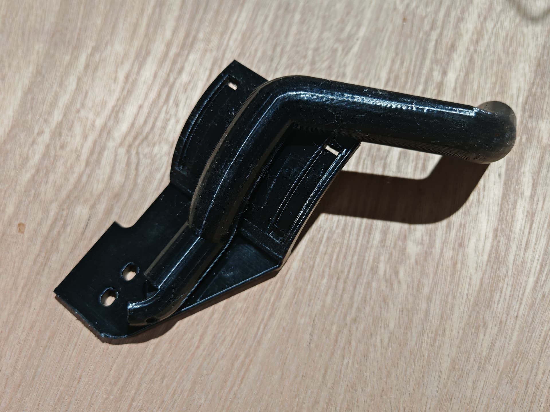
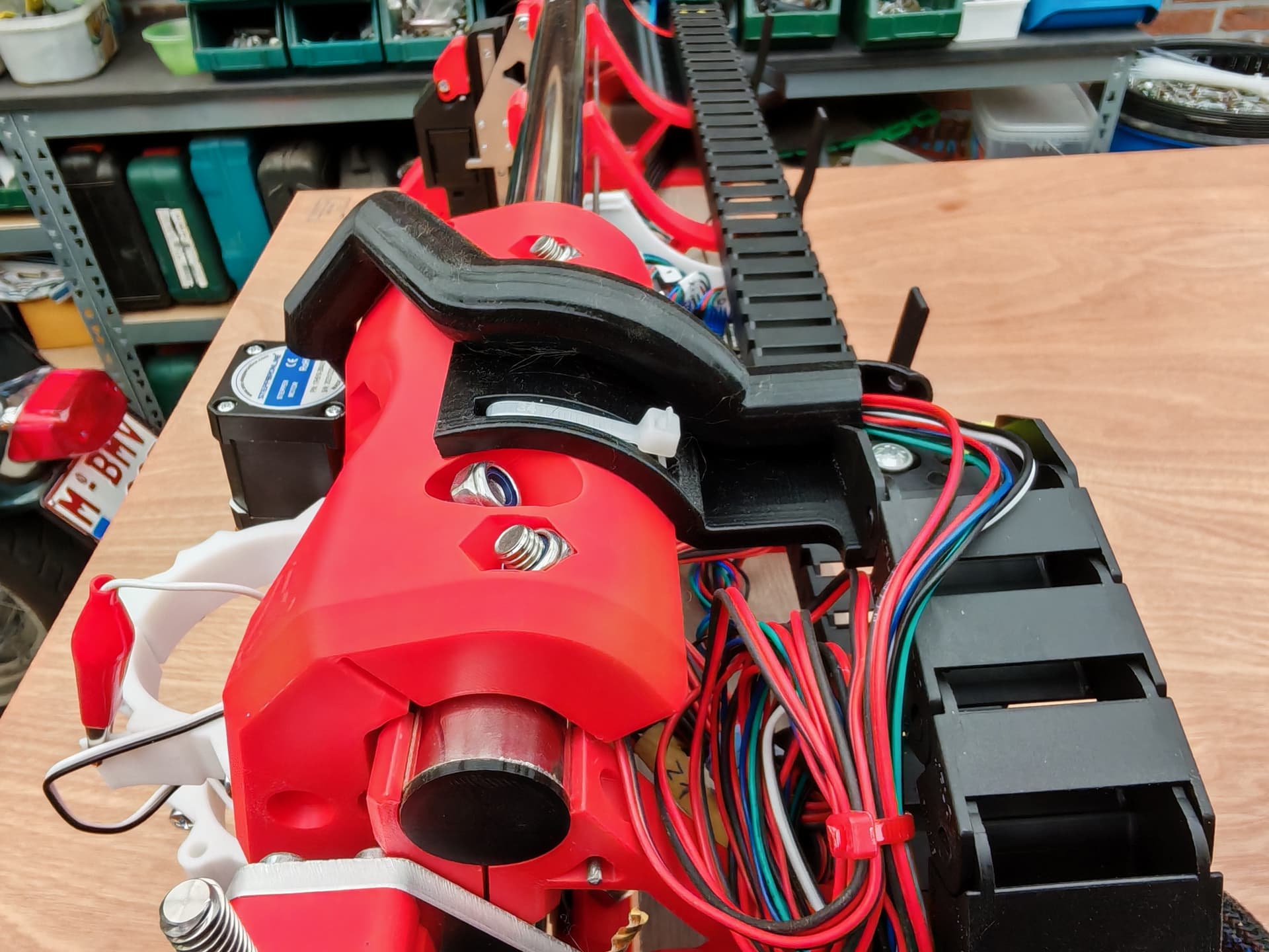
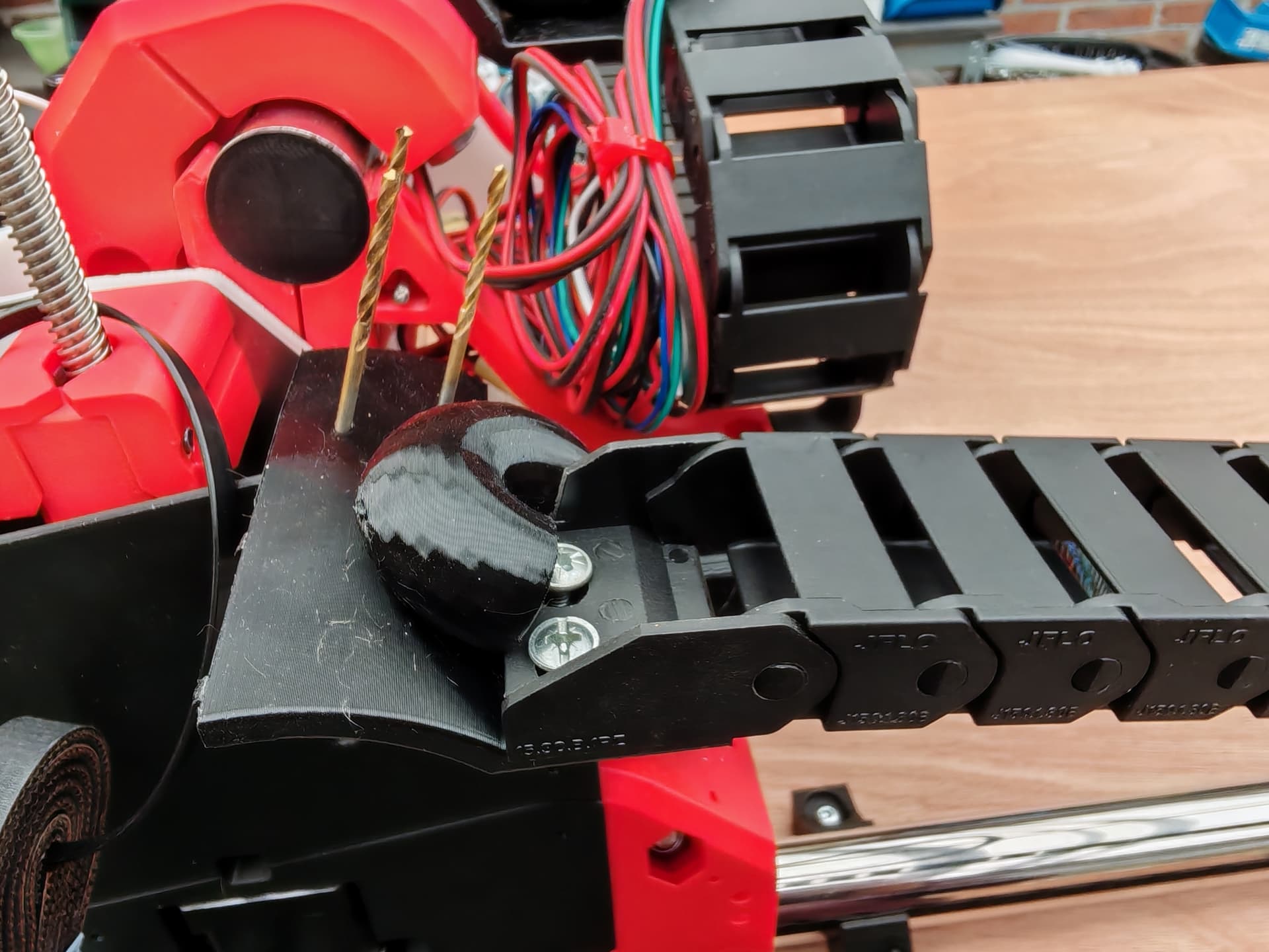
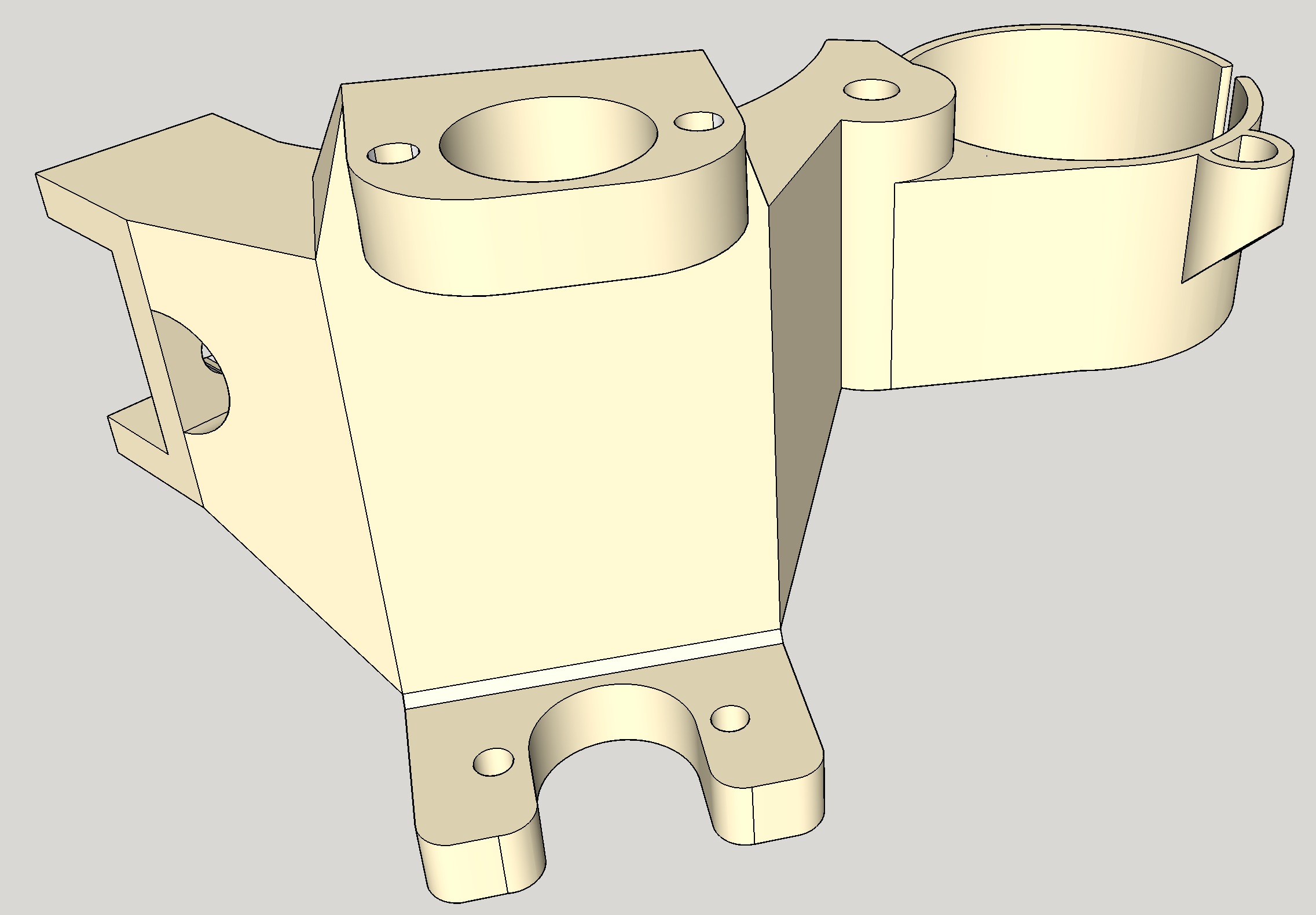
Hello, I liked this idea, so I’ve tentatively developed it and tried it out with a 3 mm stainless steel rod. With Sketchup I’ve made 3.5 mm holes into the cover and the hinge brackets (I did glue these hinge brackets in place with Loctite because they were a bit loose and wouldn’t slide around). Later, I’ll replace the stainless steel rod with a stainless steel 3 mm threaded rod. Best regards.
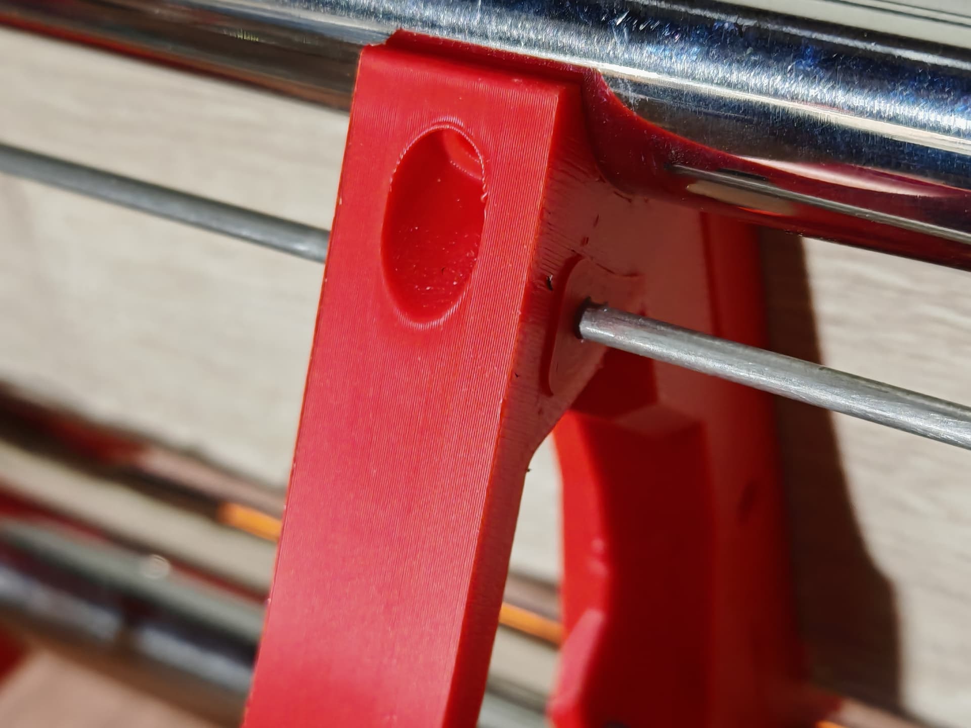
3 Likes
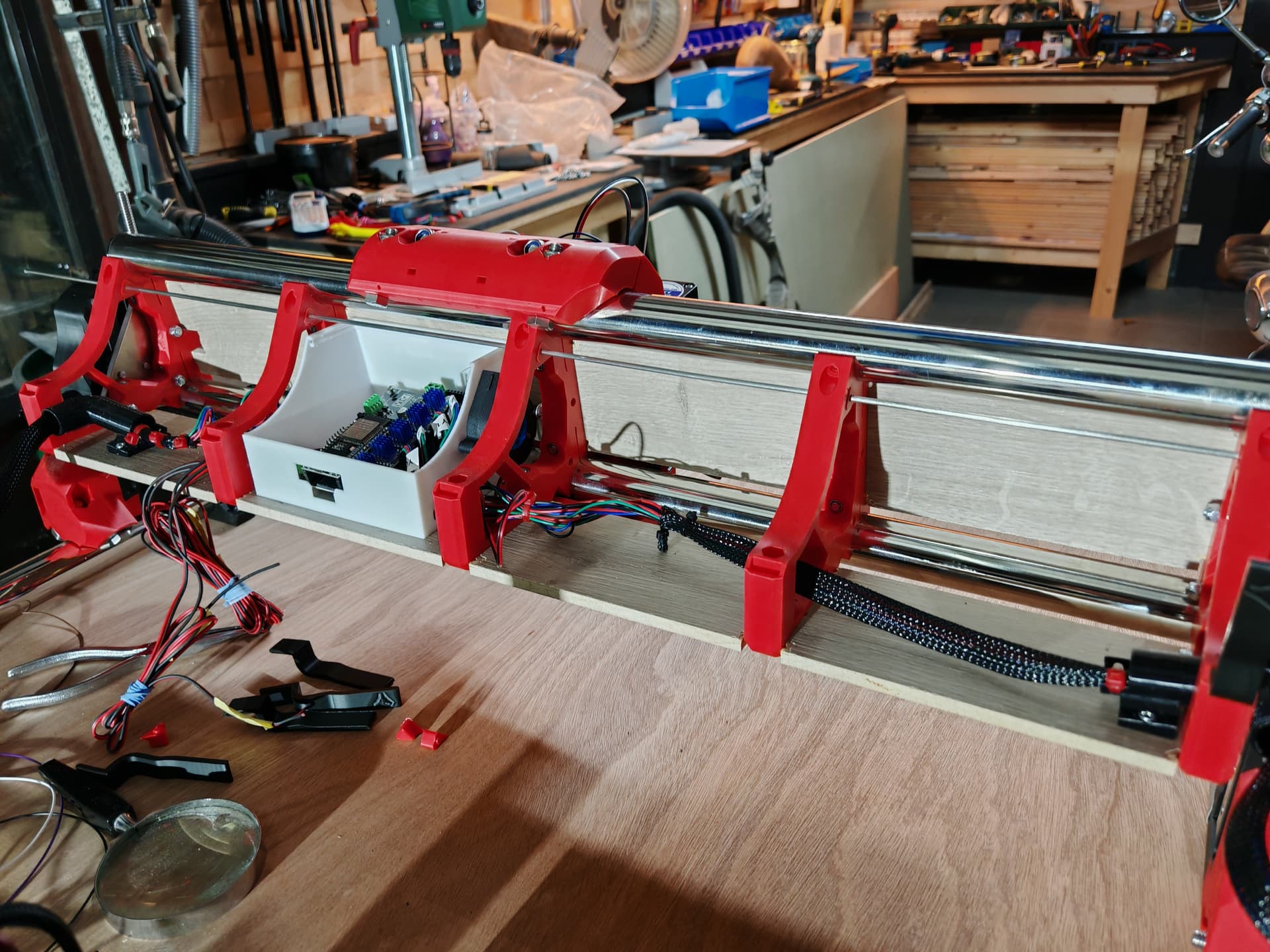
Great progress
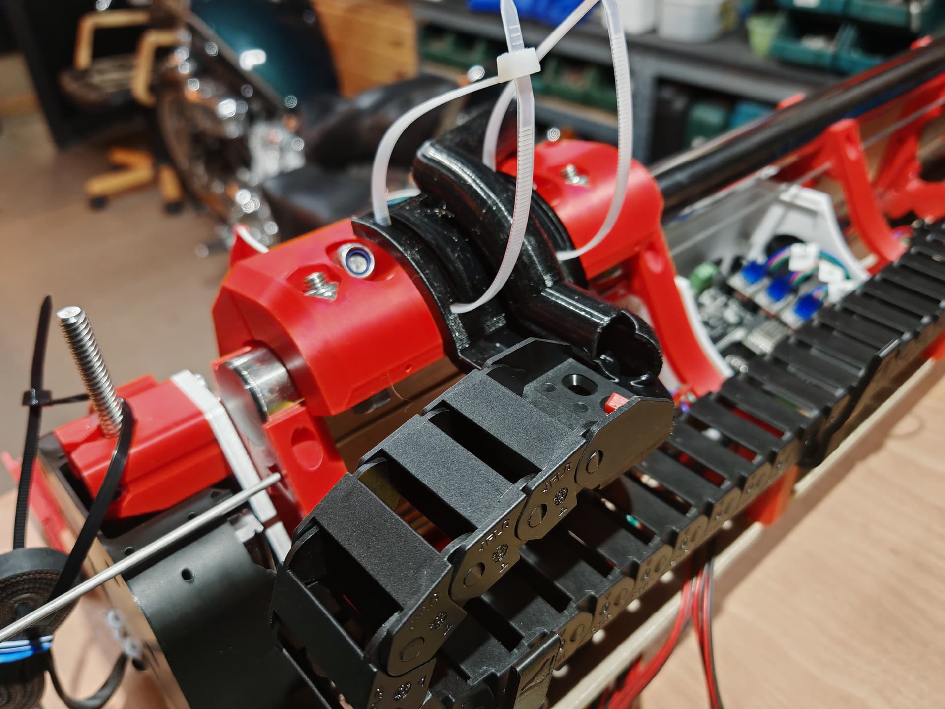
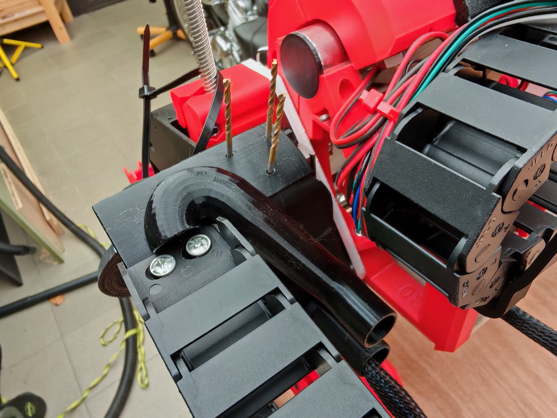
Printed tubes for the wires are really cool! Just about time to start cutting.
1 Like
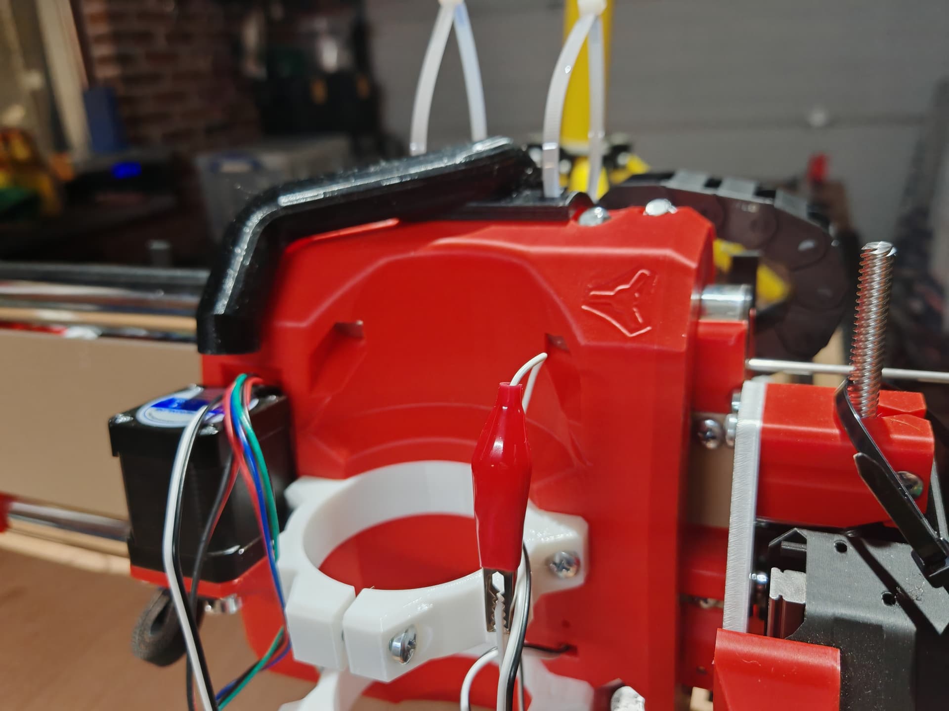
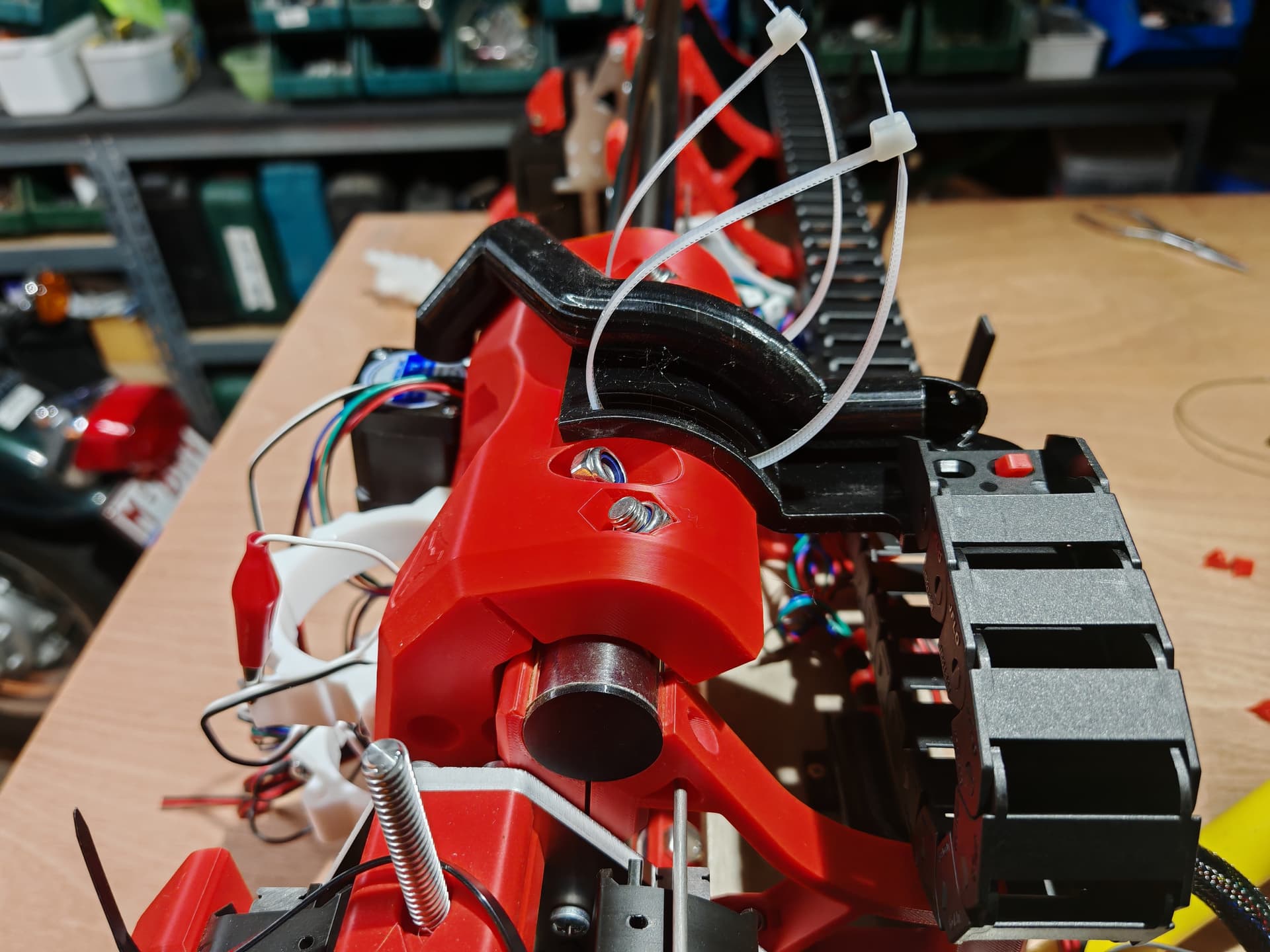
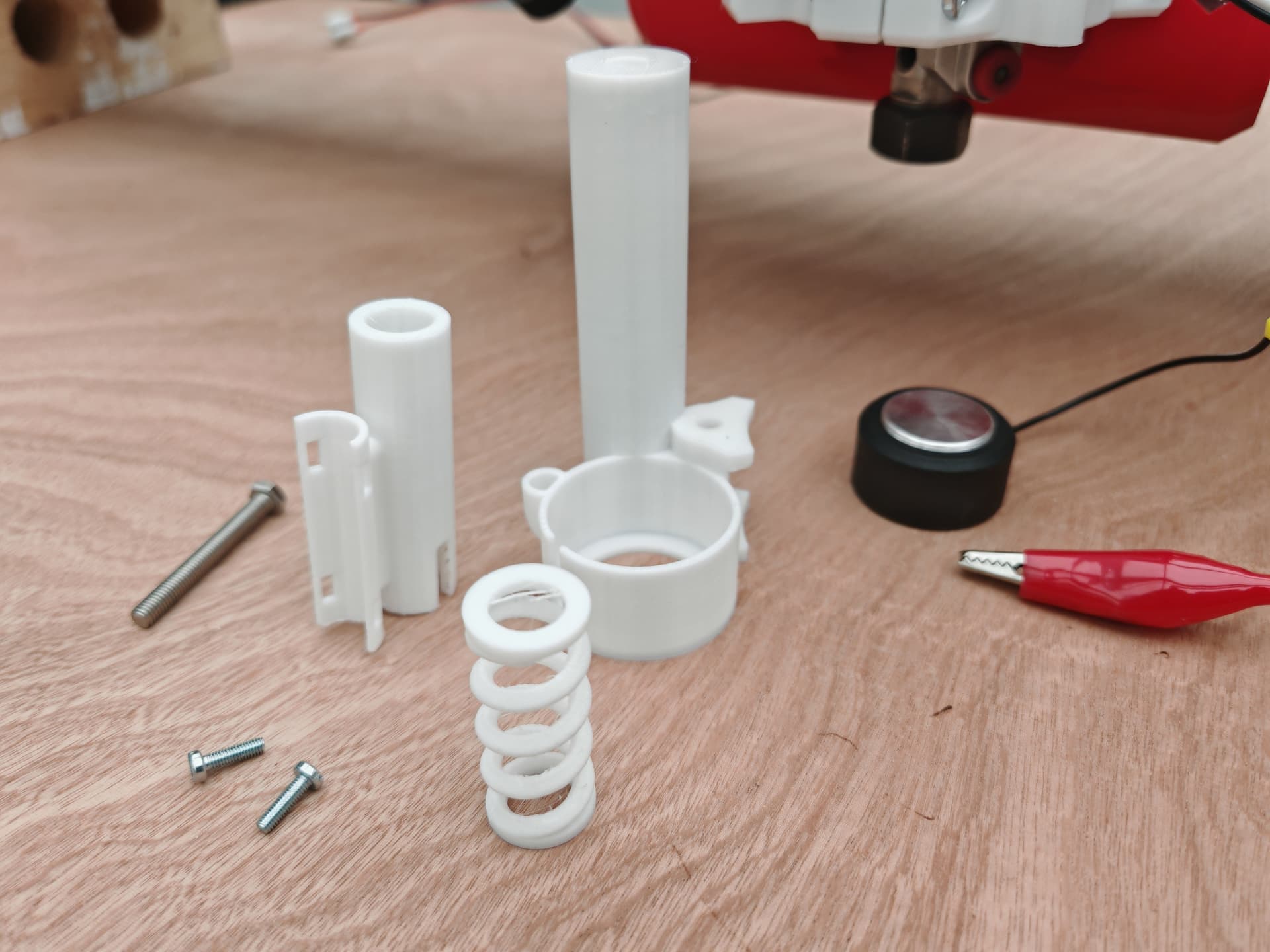
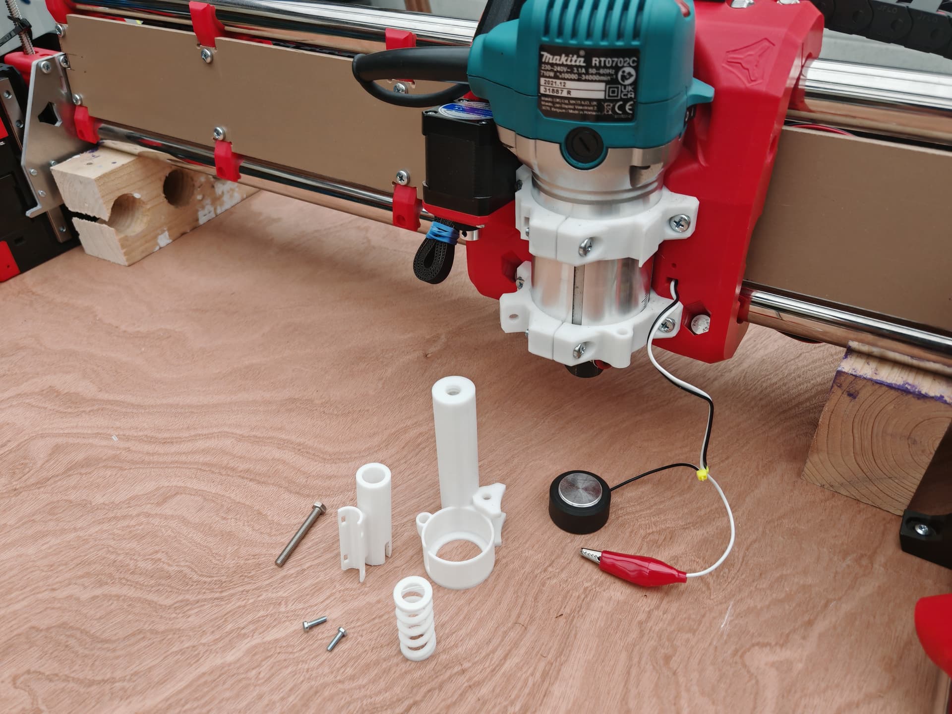
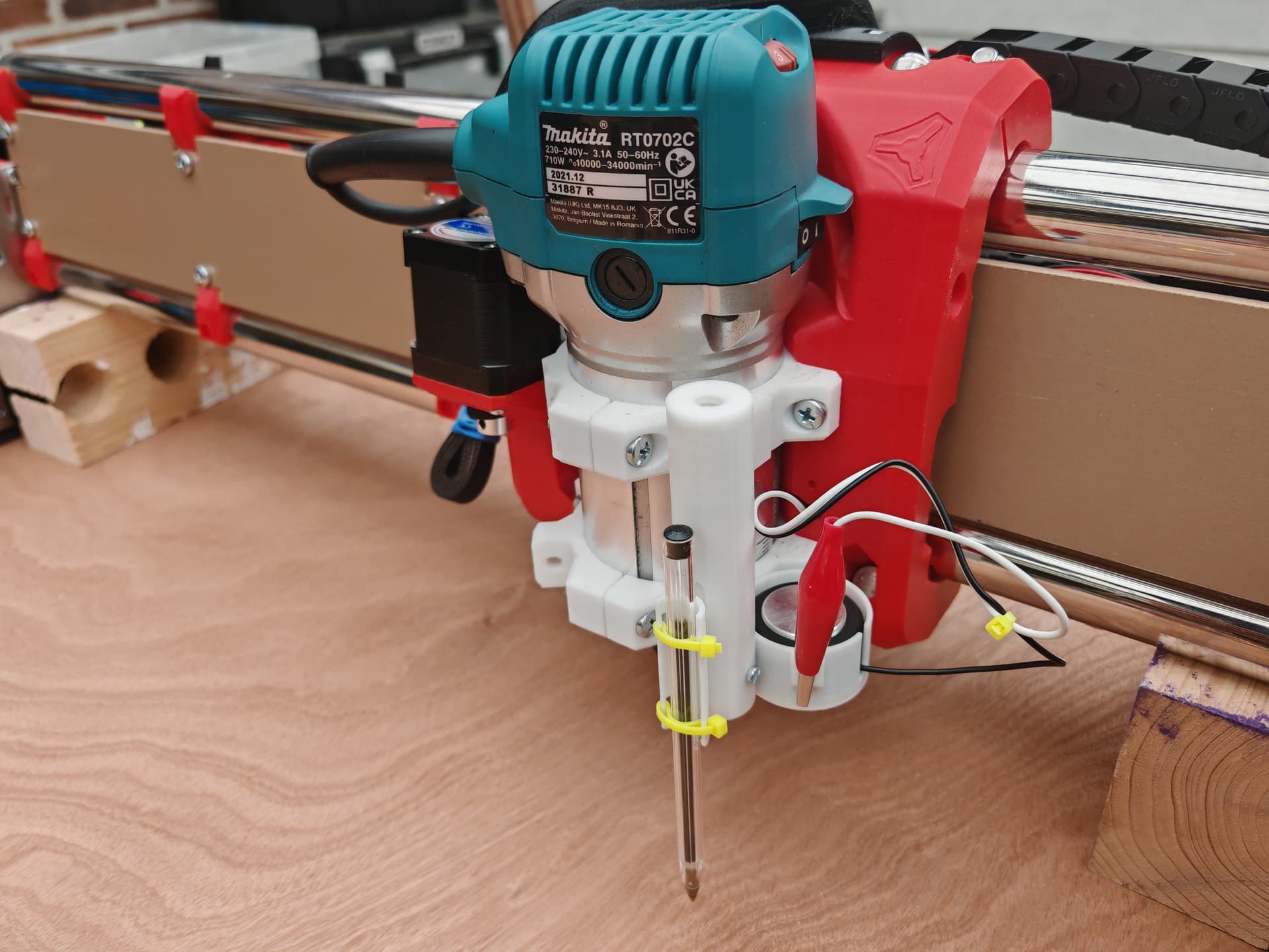
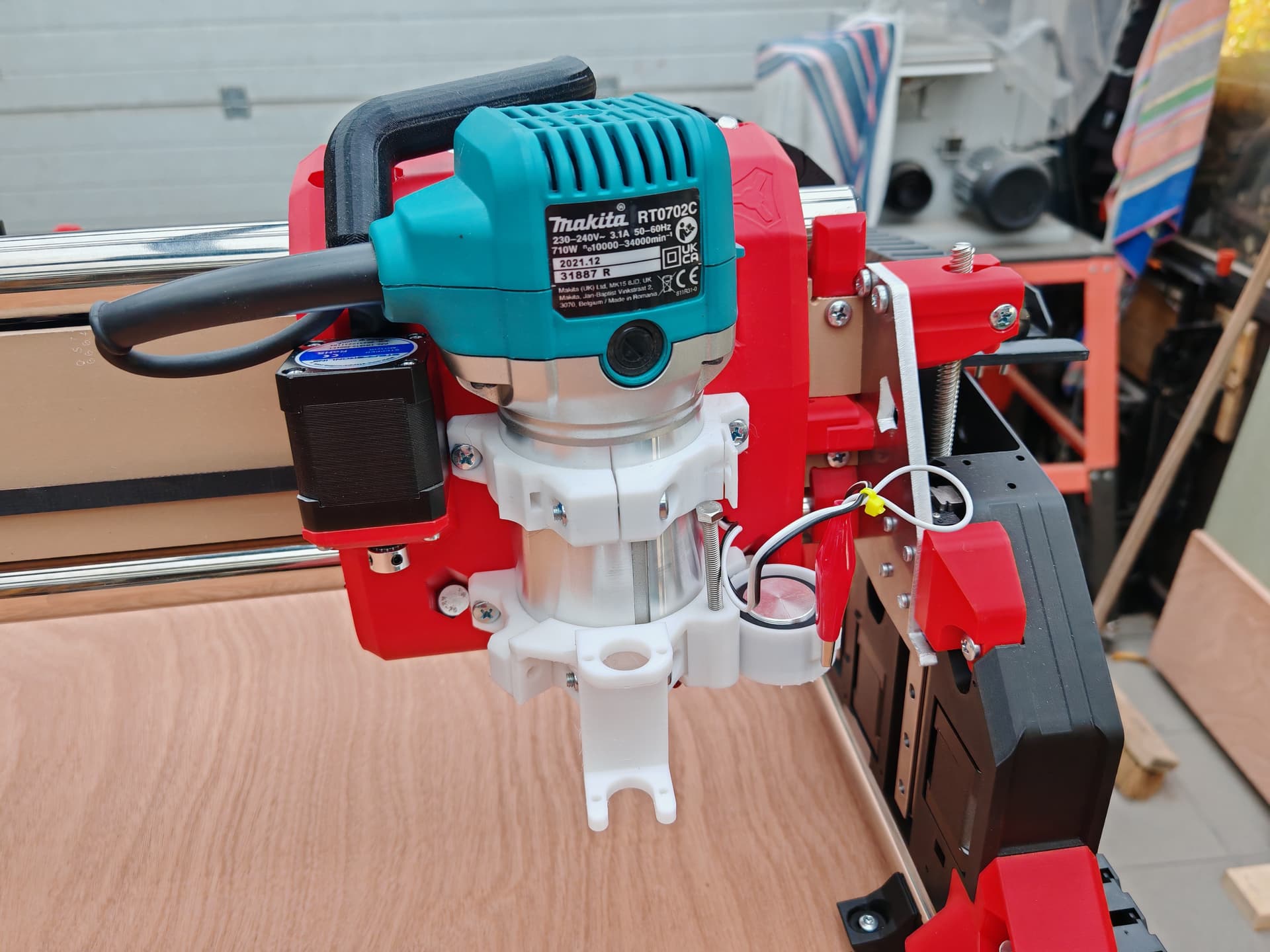
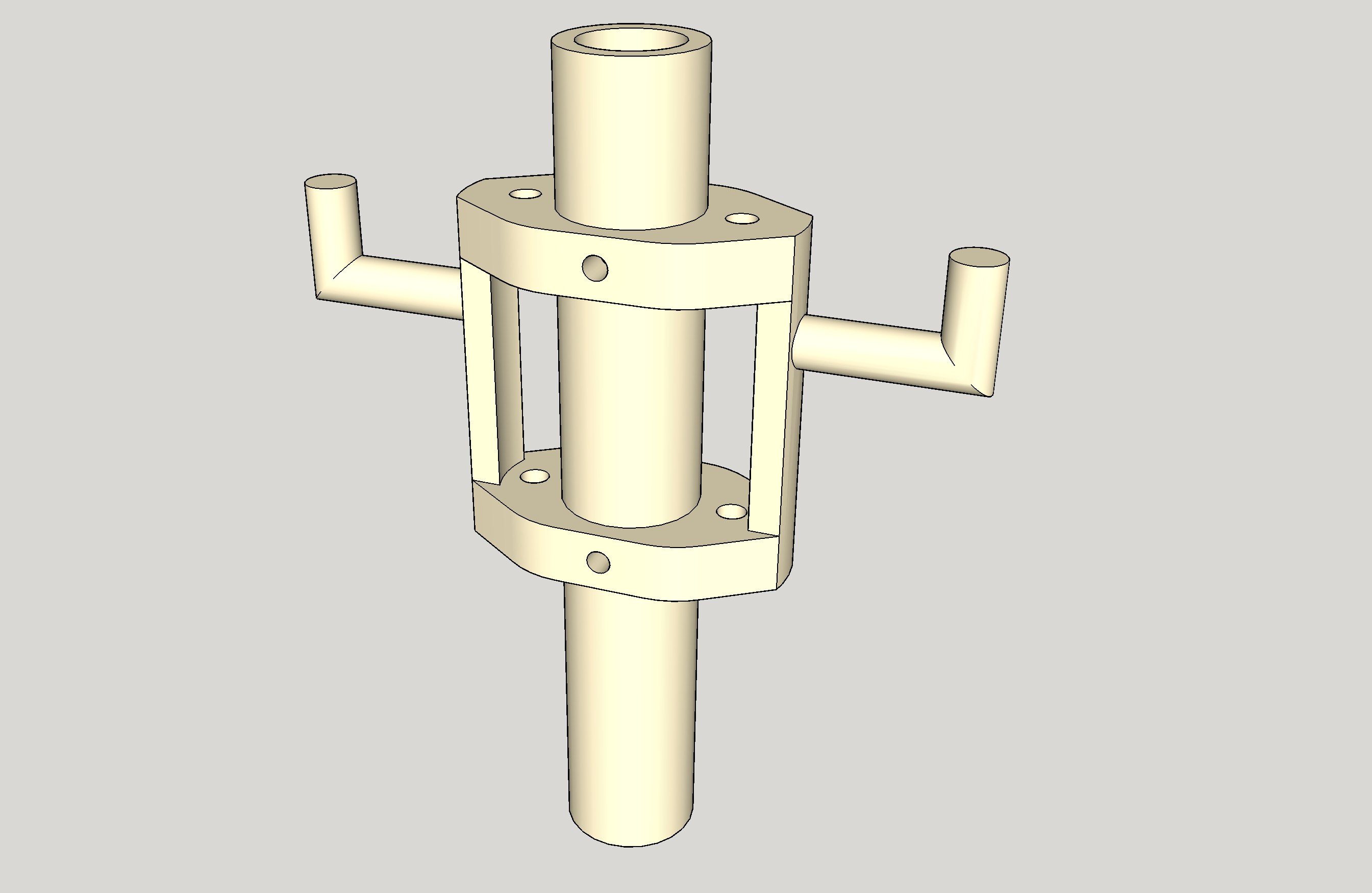
Combination of a probe holder and a pen holder (with 3d printed spring).
One more thing to try in the future. Greetings everybody.
7 Likes
Love the idea. And looks great. How does it work? I made a rather rigid simple mount. But your’s is so much nicer.
Curious, I think we are using the same mount that was available there. Does anyone know why it’s there? For this type of options I assume? Clever. @vicious1
That is there for optional mounts.
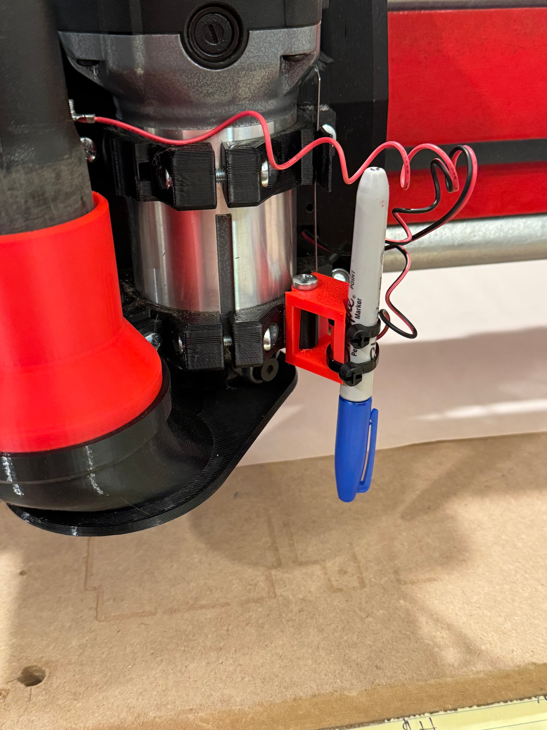
I made a pen mount that puts the tip of the pen in the makita center, and is compliant in Z only. Pen Mount for the LowRider 4 CNC by V1 Engineering | Download free STL model | Printables.com I find pens do not last long if rigidly mounted.
2 Likes
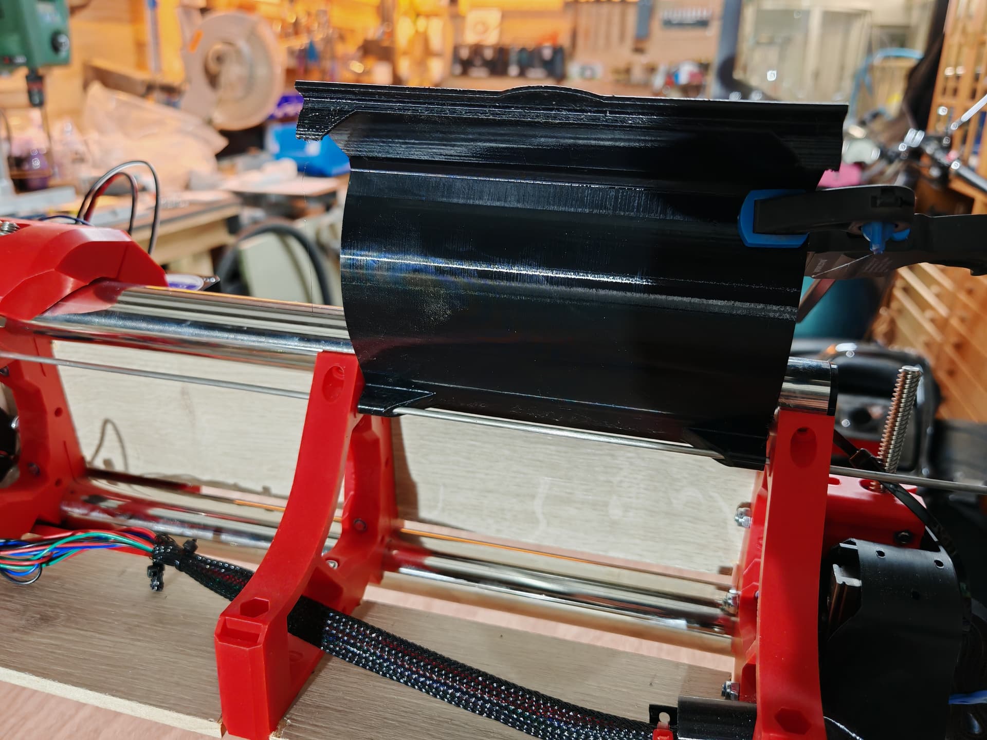
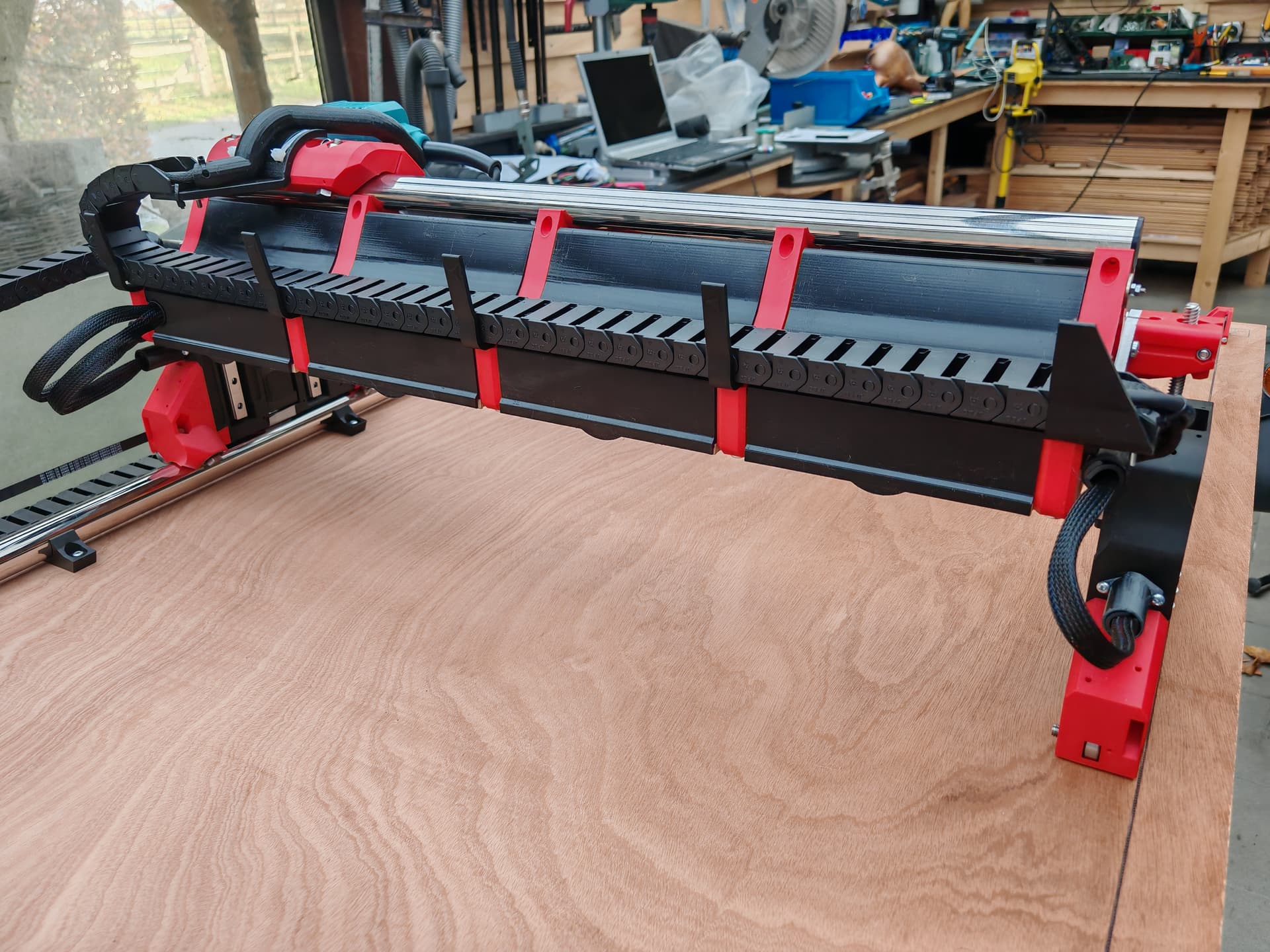
Hi everyone, back from a bit of a hiatus. We’re nearing the finals and printing the crown, not great yet. I changed the pen holder, but it’s not sturdy enough yet. Work in progress…
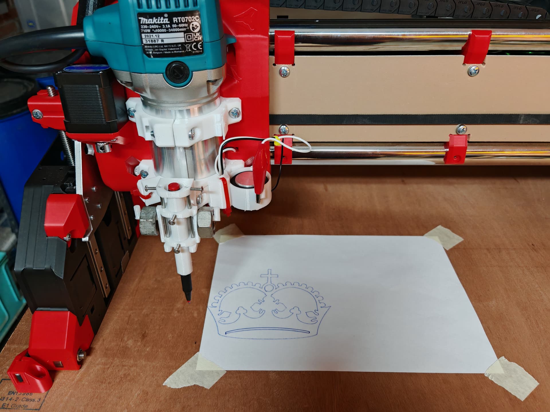
8 Likes
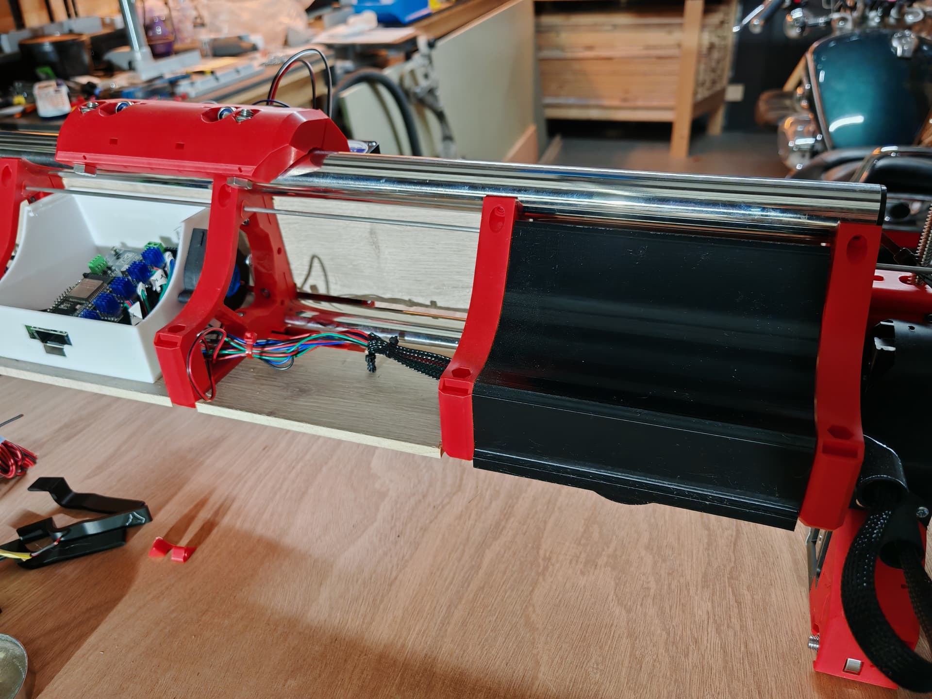
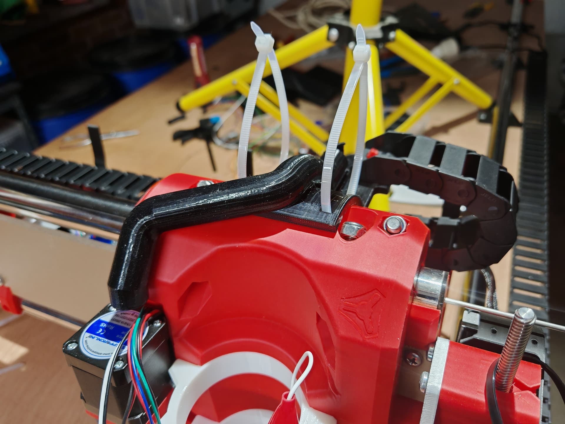
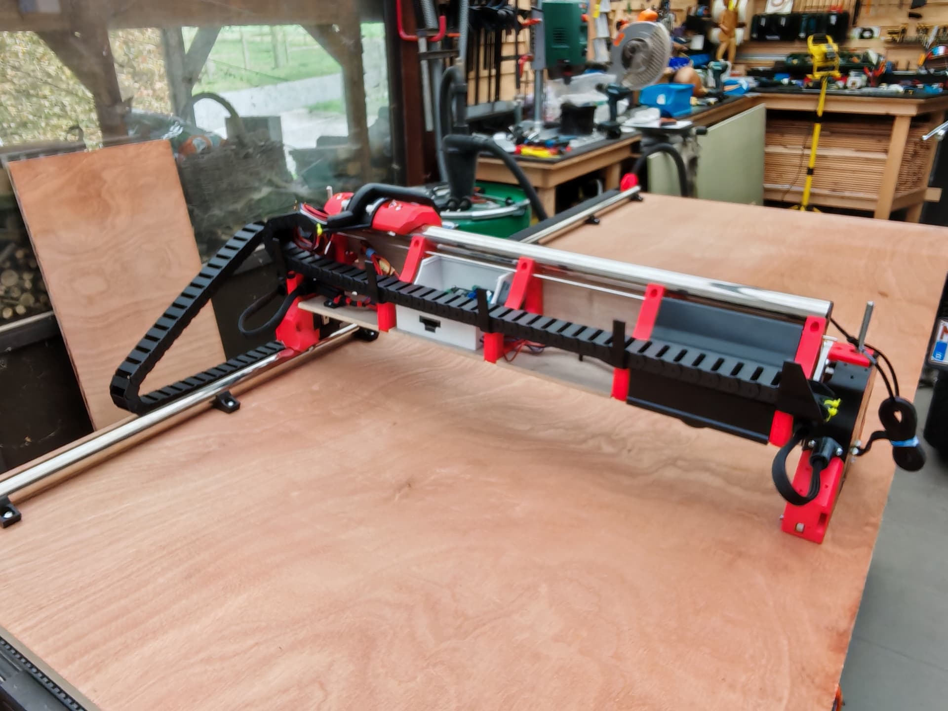
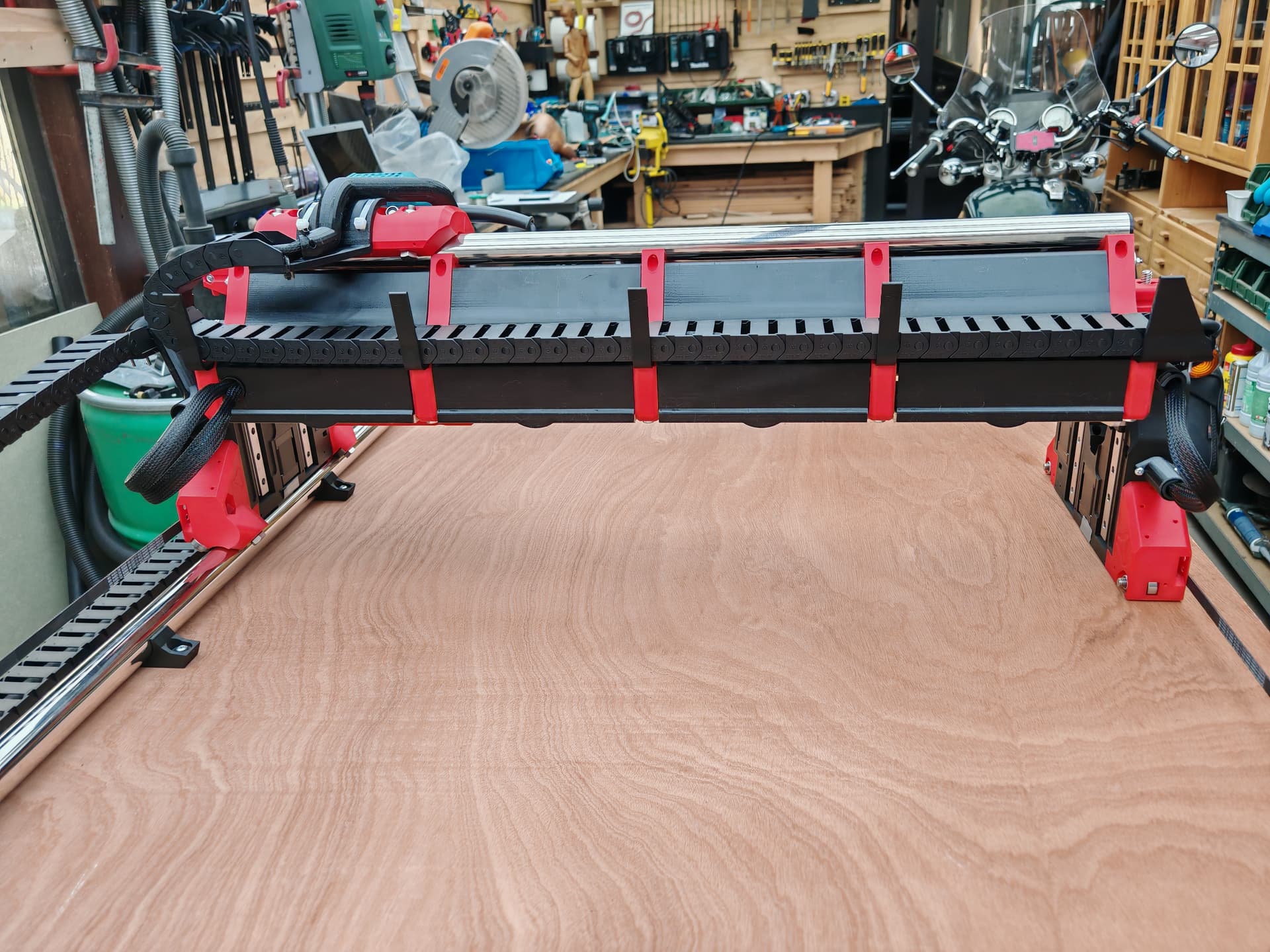
It looks to me like the X drag chain is backwards. Wouldn’t you want the anchored point on the chain to be close to the top point on the Y drag chain?
Hello, thank you for your message. You have a point there. The only way to get into the beam on the left side was in the front of the cover on the right side so I still had enough room to get into the side of the beam without any problems. Before that I took this direction of the drag chain. Greetings.
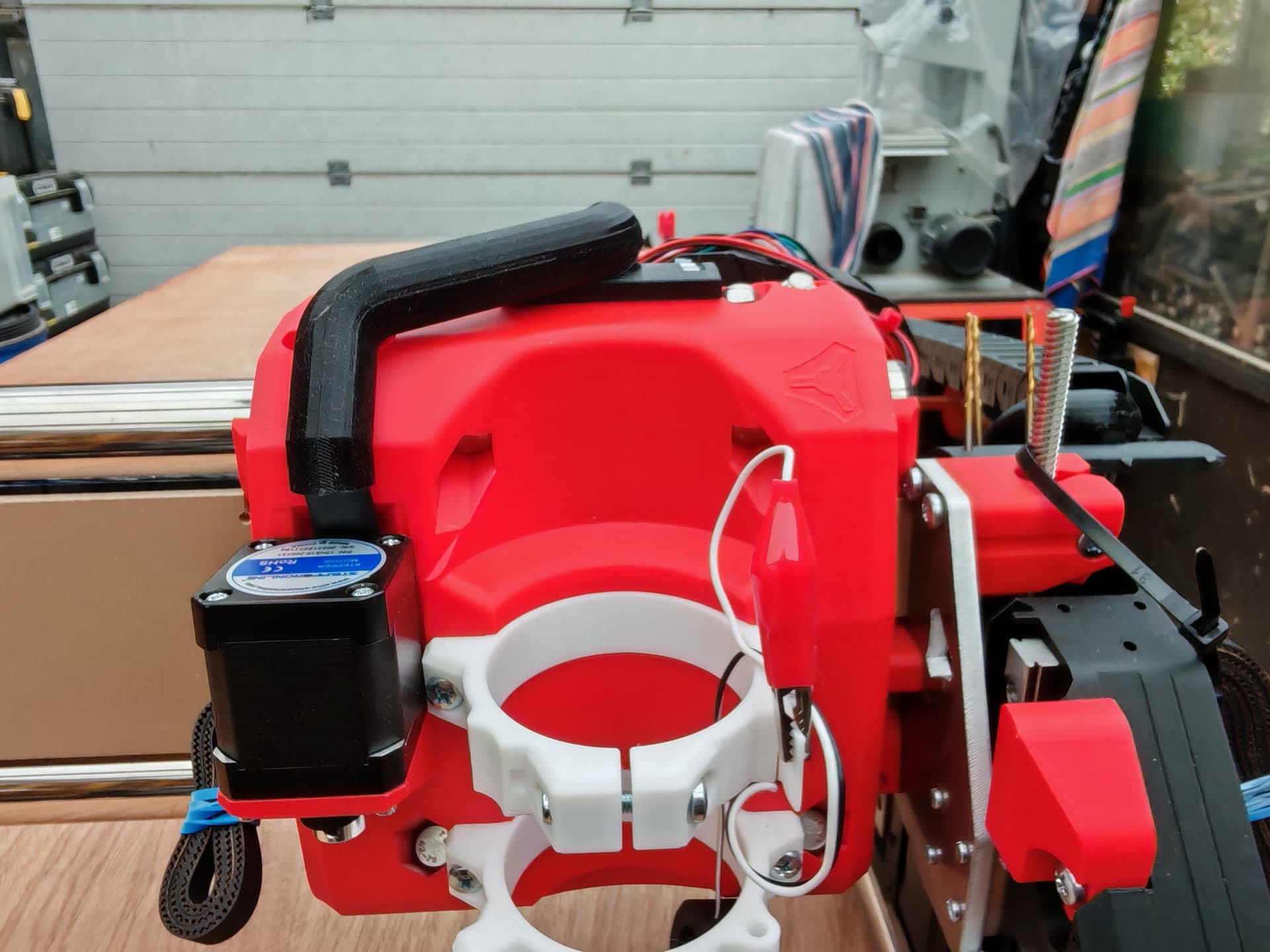
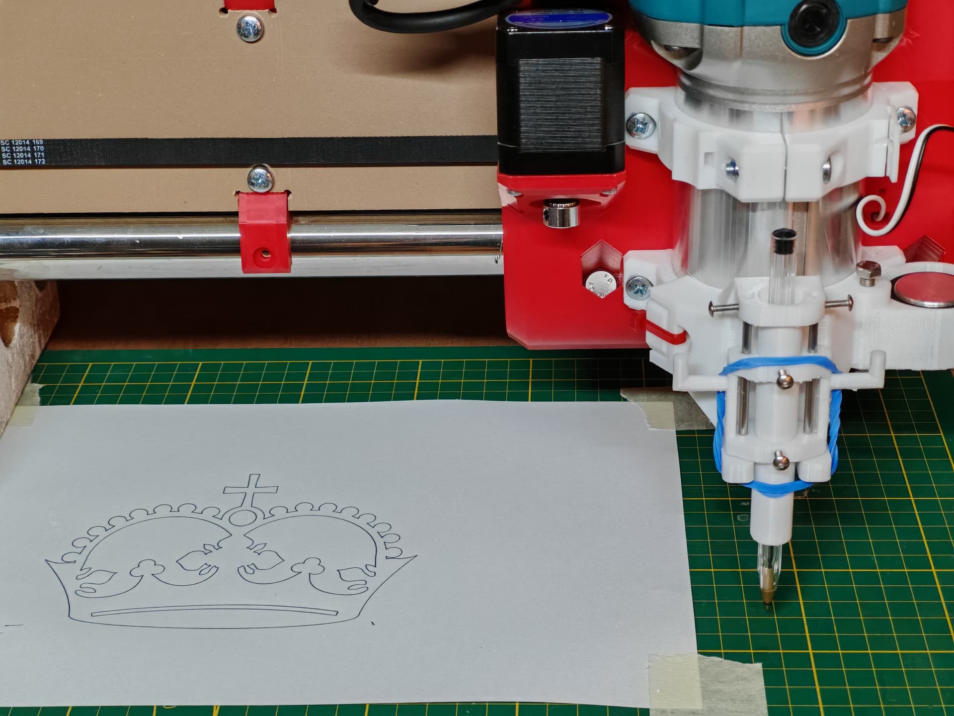
Hello everyone, I made the pen holder (+ probe holder) a lot more sturdy and with success. The pen holder can now only move in the Z direction. I am very satisfied with the drawing of the crown. On this occasion I would like to once again express my special thanks to RYAN and his staff for making it possible to build this incredible machine, I love it!!! Many thanks!!! And now to study the CNC matter a little more.

3 Likes
It’s just Ryan, the rest of us are all just community members.
3 Likes
Keep in mind that the reality of a drag chain is that the portion of the drag chain that needs to actually move starts about the center of the beam. As such you don’t need to actually get to the extreme end of the drag chain, you can shorten it and get to it a little bit inboard of the edge. You can move the machine to its limits and see how much of the drag chain never needs to flex. (This is of course also true for the Y axis.) the drag chain can serve as a protective conduit for the wiring as well, and of course you may want the aesthetic aspect of the drag chain being full length, but since that’s unnecessary cost to me, I prefer to use as little of it as possible. My drag chains tend to go from just shy of the halfway mark to the moving part, sometimes with a rigid conduit piece on the loose end to protect/contain the wires.
2 Likes
Hello Dan, I thank you for your message and yes you are indeed right, half of the drag chain is too much, it’s good to know for the future.
2 Likes
Hi Jim, I didn’t knew this, so now a big big thank you for the great machine RYAN and also a big thank you for the many responses from the community members. I enjoyed it very much.
3 Likes
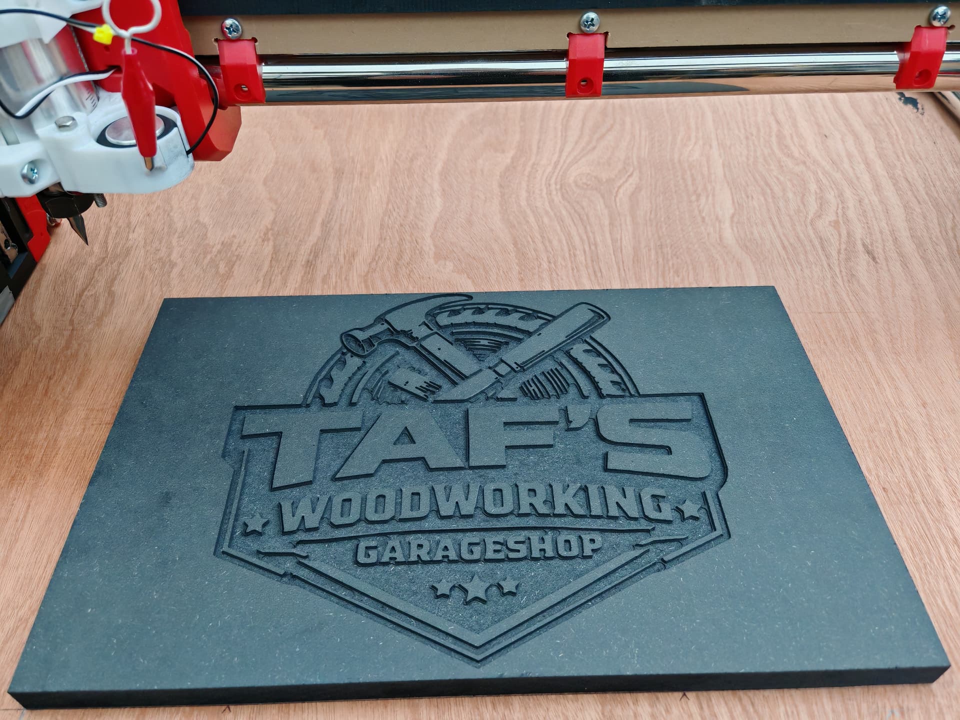
I am very satisfied with the engraving work on black MDF.
Now I am ready to make the spoilboard
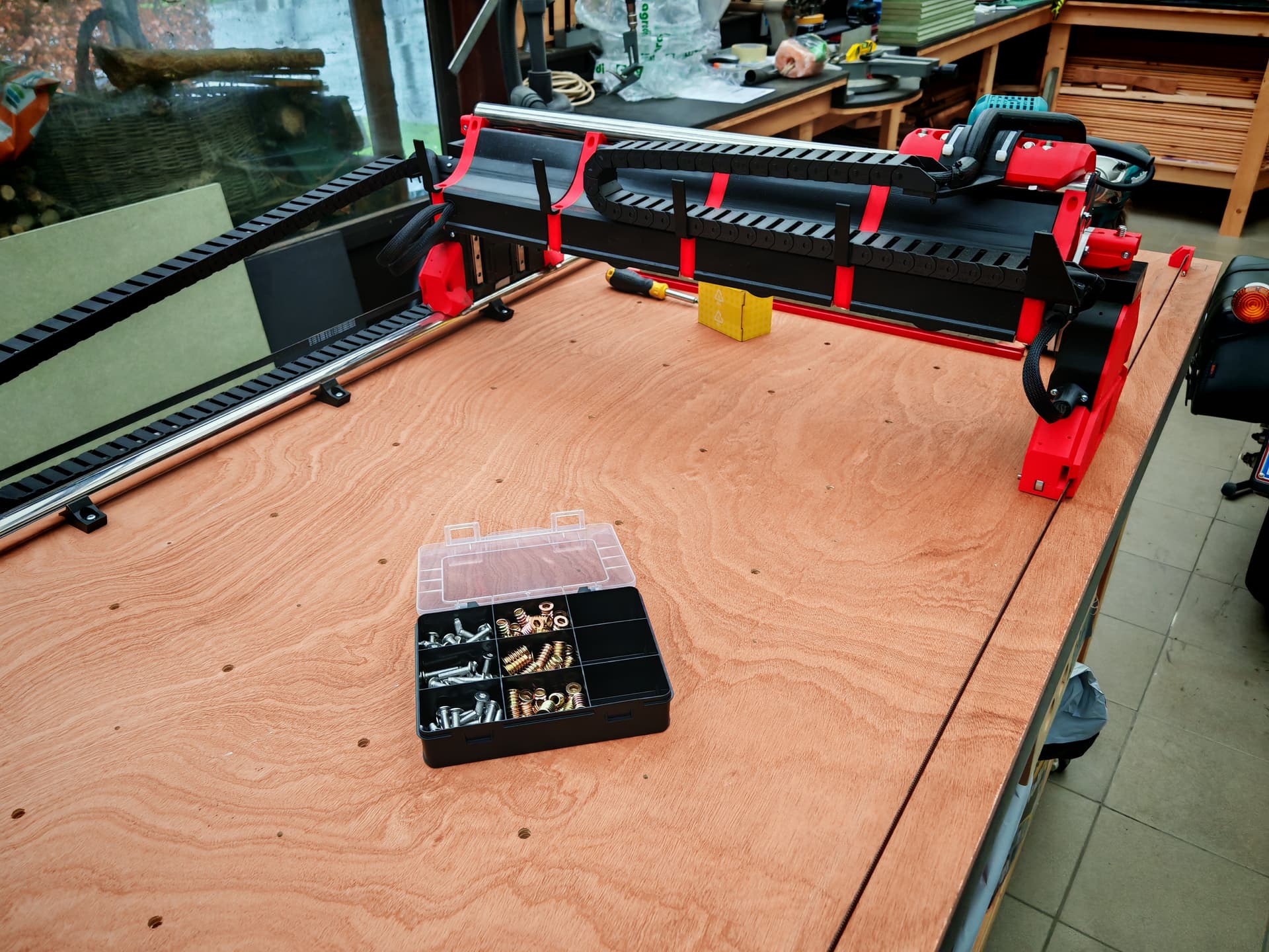
The big holes are for te screw nuts to hold the green MDF.
The little holes are for fixing the red T-tracks.
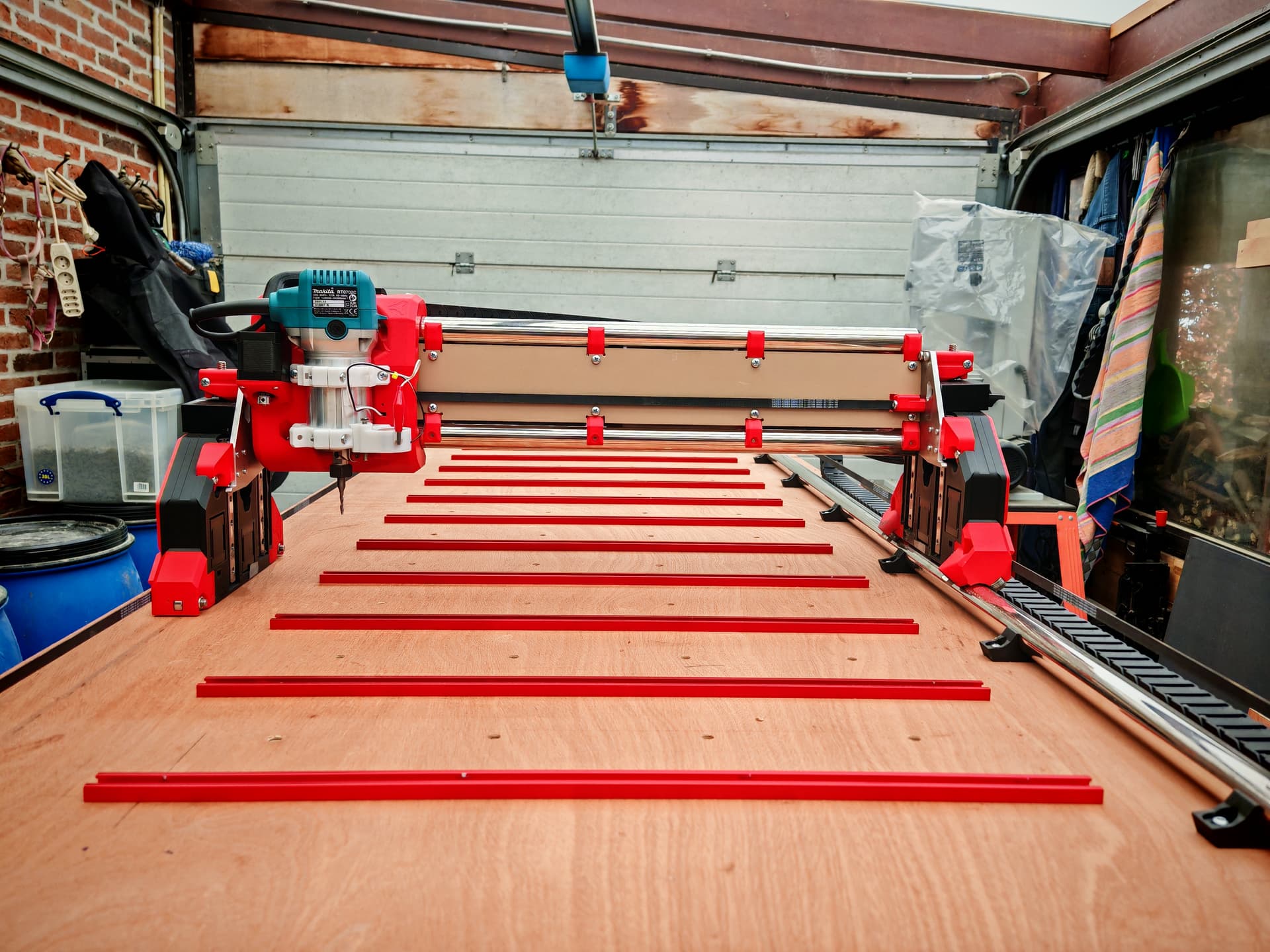

I’m really amazed of the top accuracy of this machine, I’m having a lot of fun with it, thanks Ryan.
9 Likes
Great looking build! The sign came out really nice as well.![]()
1 Like
Pretty sure that is the first time I have ever seen Black MDF before. That came out awesome!!!
3 Likes
I still have a lot to learn but I’m already enjoying it very much.
Thanks for your response.
4 Likes